1
Required Tools
Rubber Mallet
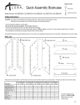
Quick Assembly Storage Cabinets
Small Blade
Screwdriver
Model Numbers: RTA 7000, RTA 7001
Small Phillips
Screwdriver
Safety Instructions
CAUTION: Use caution when handling and assembling metal parts. Metal may have sharp edges or corners.
Manufacturer recommends the use of protective gloves when assembling product.
• This unit should be installed on a level surface.
• Do not use this unit as a step ladder. Do not climb on the unit.
• This unit is not intended to be used in any other manner than for storage.
• Do not exceed the manufacturer’s recommended weight capacity of 150 lbs. / 68 kg. on each shelf. Always distribute weight evenly on shelves.
• The manufacturer recommends the storage of heavier items on bottom shelves.
All assembly instructions must be followed exactly or the unit may not be assembled correctly and may not be stable. Assemble the unit on level surface.
Parts List
Top
B - Right Side Panel
Top
D - Right Back Panel
Top
F - Right Door
Plastic
Door Rod
Guide
Square
Holes
Tabs
Handle
Mounting
Holes
G - Door
Rods
Bottom
Bottom
Plastic
Door Rod
Guide
A - Left Side Panel
C - Left Back Panel
E - Left Door
Please refer to the chart below to confirm that you have the
correct number of parts for your product. Products are
listed by their model number.
Part Name
Left Side Panel -A
Right Side Panel -B
Left Back Panel - C
Right Back Panel - D
Left Door - E
Right Door - F
Door Rods - G
Handle - H
Top - I
Shelf - J
Shelf Clips - K
Bottom - L
Kick Plate - M
RTA 7001
RTA 7000
42" - 2 Shelf
1
1
1
1
1
1
2
1
1
2
4
1
1
72" - 4 Shelf
1
1
1
1
1
1
2
1
1
4
8
1
1
Bottom
I - Top
J - Shelf
H - Handle
Assembly
K - Shelf Clip
For customer service
please call: 1-773-475-3000.
Please have your model
number handy.
L - Bottom
Notched Corners
M - Kick Plate
4-008/1
Quick Assembly Storage Cabinets
Page 2
Assembly Instructions
TIPS FOR EASIER ASSEMBLY:
• 2-person assembly is recommended.
• Assemble the unit on a flat surface.
• Some locking tabs may flatten out or bend open during transport.
Adjustments can easily be made using a small blade screwdriver with light pressure.
Locking Tab
Can be adjusted open or closed to ease assembly
Step 1 - Back Assembly
A) Lay the two back panels on a flat
surface. Position as illustrated.
Right Back Panel - D
B) Place the Right Back Panel (D) over the
Bend is up
Square
Holes
Left Back Panel (C) inserting the tabs into the
matching holes.
Tabs
C) Once all the tabs are started, slide the Back Panels
in opposite directions to fully engage the tabs.
Left Back Panel - C
Bend is up
D) Tap the tabs down with a rubber mallet to
tighten the connections.
NOTE: On the 72” model, use care when handling
the Back Panels. They bend very easily if not handled properly.
Use 2 hands and NEVER put your fingers in the slots.
Right Back Panel
Left Back Panel
When lifting, position both hands near the center
of the Back Panel as shown to avoid bending it
Insert the tabs into the matching holes
Slide the panels to fully engage the tabs and tap them down
Step 2 - Side Assembly
A) While the Back Panels are still lying on a
flat surface, lift the outside edge of the
Right Back Panel (D) and slide the L-shaped
bend of the Right Side Panel (B) under it.
Right Side Panel - B
B) Insert the tabs on the Right Back Panel (B)
into the matching square holes in the
Right Back Panel (D).
Lift the edge of Back Panels
and set them over the Sides,
inserting the tabs through the
matching square holes.
IMPORTANT:
Make sure the bends on the Side
Panels are on the same side
as the Back Panels
Square
Holes
Right Back Panel - D
C) Once all the tabs are started, slide the Side
and Back Panels in opposite directions to fully
engage the tabs.
D) Tap each of the tabs down with a rubber mallet to
Left Back Panel - C
Square Holes
on Back Panels
tighten the connections.
E) Repeat the steps with the Left Side Panel (A).
Tabs
on Side Panels
Left Side Panel - A (shown transparent)
Slide the panels to fully engage the tabs and tap them down
Quick Assembly Storage Cabinets
Page 3
Step 3 - Bottom Assembly
A) Position the Kick Plate (M) as illustrated and
The Kick Plate slides into the
channel on the Side Panels and
locks into place.
Channel
begin installation by lifting its right end
upwards inside the channel on the Right Side
Panel B).
Kick Plate - M
Right Side Panel - B
B) Push the Kick Plate upwards until the
crescent tab on the Side Panel engages
the square hole on the Kick Plate (M).
Note: this is a tight fit. A loose connection
would result in an unstable unit.
C) IMPORTANT: Bend the tab on the bottom of the
Side Panel 45 degrees inward to lock the Kick Plate
in place.
D) Repeat the procedure for the left side of the Kick Plate.
Cresent Tab on Side Panel
NOTE: Kick Plate
fits inside the bend
on the Side Panel
Lift Kick Plate
into the channel
until it locks
Bend tab
45 degrees
inward to
lock the
Kick Plate
Square Hole
on Kick Plate
Tab bent
and Kick
Plate
locked in
position
Angle the Bottom to engage the supports on the Back and Side Panels.
Tilt it forward until it’s front edge goes OVER the bend on the Kick Plate.
IMPORTANT:
The notched corners on the
Bottom (L) must face the Back
Panels
Bottom - L
The Bottom (L) must engage
the supports located on each
of the Back and Side Panels
Support
Carefully stand
the unit upright
E) Install the Bottom (L), by placing it in the cabinet with the notched corners
Tap Bottom down
to fully engage
the supports
toward the Back Panels.
F) Angle the Bottom (L) as illustrated and engage the supports located on the
two Back Panels. Note: as with the tabs, some adjustment to the supports on the
Side and Back Panels with the screwdriver may be necessary.
G) Gradually tilt the front edge of the Bottom (L) forward, making sure that it engages
The front edge of
the Bottom is
OVER the bend
on the Kick Plate
the supports located on the Right and Left Side Panels and goes over the bend on
the front of the Kick Plate (M).
H) Carefully stand the unit upright and tap the Bottom (L) down. Make sure the
Bottom (L) has full engagement in the supports on the Back and Side Panels.
The Bottom must fully engage the supports located on
the Back and Side Panels
Quick Assembly Storage Cabinets
Page 4
Step 4 - Top Assembly
A) Begin inserting the posts on the Top (I) into the
channels on the Right and Left Side Panels. Starting with
the Top on a slight angle may help.
Posts
Top - I
B) Once both posts are started. Tap evenly down
on the Top (I) until it is just past the Side and
Back Panels. Make sure the Top (I) is going
OVER the Side and Back Panels.
Channel
Insert the
Posts into
the channel
on each of
the Side
Panels
C) Check under the Top (I) to make certain
that the Side and Back Panels are INSIDE
the supports.
Begin lowering the
Top by tapping just
over the Posts
Keep the Top as
level as possible
D) Tap the Top (I) down around the edges until the
tabs on the Side and Back Panels snap into the square
holes on the supports .
IMPORTANT:
The Top must be
OVER all the
Side and Back
Panels
Tap the Top down
evenly until it is
just past the
Side and Back
Panels
Tap down the Top
evenly until the Tabs
lock it in place
Back Support
Back Support
IMPORTANT:
The Side and Back Panels
The Tabs on the Side and
Back Panels lock into the
square holes on the
Supports
must be inside the supports
located under the Top
Square Hole
Side Support
Back Tab
Side Support
Square Hole
Side Tab
Step 5 - Shelf Installation
View under Top showing Side and Back Panel
tabs fully engaged
View under Top showing Side and Back Panel
supports and partial engagement
Insert the rear
of the Shelf
into the
slots
A) At the desired shelf height, insert 2 Shelf
Clips (K) into the holes located inside
the front edges of the Side Panels.
Shelf Clip - K
Shelf
Clip - K
B) Angle a Shelf (J) into the cabinet above
the installed Clips with its rear tilted down.
C) Insert the rear of the Shelf (J) into the slots
in the Back Panels that are closest in height
to the installed Shelf Clips.
Shelf -J
Insert the top of
the Clip and angle it
down
Tilt the front
of the Shelf
down and
rest it on
the Shelf
Clips
D) Tilt the Shelf (J) down until it rests on the
Shelf Clips. If the Shelf is uneven,
reposition the Shelf Clips into appropriate
locations to level it.
E) Repeat this process for all of the shelves.
Snap the botton of
the Clip into the hole
Reposition
the Shelf
Clips to level
the Shelf if
necessary
Quick Assembly Storage Cabinets
Page 5
Step 6 - Door Installation
A) Select the Right Door (F), with the handle holes, and
position the Hinge Pins over the matching hinges on the
Right Side Panel. NOTE: If some of the Hinge Pins were
bent during transport, bend them back to align them with
the Side Hinges
Door
Hinge
B) Once all the Door Hinge Pins are engaged into the holes
Door
Hinge
Pin
Handle
Holes
on the Side Hinges, swing the door slightly and apply mild
downward pressure until the door is fully seated.
The Pins on the
Door Hinges slide
into the Side Hinges.
C) Repeat the steps to install the Left Door - E.
Side
Hinge
NOTE: the cabinet must be on a level surface for the doors
to align properly.
Left Door - E
Step 7 - Handle Installation
Right Door - F
Close-up of Hinges
A) Remove the 3 screws from the
back of the Handle (H).
Lockwasher Screw
No. 8-32 x 1/4”
B) Insert the Handle (H) into the Right
Door (F) and fasten securely with 2 lock
washer screws. Make sure the Handle is
in the vertical (closed) position.
Handle should
swing counter
clockwise to
open cabinet
Remove the screws
from the Handle.
Lockwasher Screw
No. 8-32 x 1/4”
C) Insert the cam through the tear-drop opening and place it
onto the square shaft on the back of the Handle (H).
D) Take one of the Door Rods (G) and insert the end without the hole
into the bottom plastic rod guide on the Door. Place the hole in the
other end of the Rod (G) on the bottom pin on the cam. Repeat
the process with the top Door Rod.
Secure the Handle in
the vertical (closed)
position.
Plastic Rod Guide
E) Attach the holding plate with the counter-sunk screw.
NOTE: Tighten the screw securely. If the screw comes
loose, the rods can fall off. This may result in a jammed
door and potential damage. Turn the handle to the “open”
position before closing doors.
Top Door Rod
Cam is through the
tear-drop opening
Cam
Pins on Cam
Countersunk Screw
Cam is on the
square shaft with
the pins outward
Bttm Door Rod
Position cam through the
tear-drop opening on the door
and onto the square shaft.
Position the Door
Rods through the
plastic guides and
onto the pins on the
cam.
Holding Plate
Attach the holding
plate. Make sure the
screw is tight.
After assembly is complete, MILD SOAP and WATER can be used to clean the unit by wiping with a SOFT CLOTH.