1
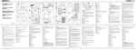
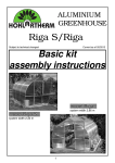
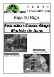
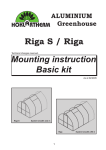
ALUMINIUM
Greenhouse
Riga XL
As at 10/2009
Assembly
Instructions
Type IV
Type V
Type VI
Dear Garding Friend,
thank you for buying a top quality greenhouse from HOKLARTHERM in Germany.
Please read these Assembly Instructions and helpful suggestions carefully. If you
follow them step by step you should not have any difficulty assembling your
EXTRA LARGE RIGA Greenhouse.
Good Luck!
What to do First:
Check all the boxes you have received. Make sure you have received the correct
number as shown on the Bill of Lading from the freight carrier. If you are missing a
box or if any of the boxes are damage please write this down on the Bill of Lading,
before the driver leaves.
Note:
Please do not refuse any of the boxes or the whole shipment, because of any damage. We will gladly replace any damaged items. Sending replacement parts is much
simpler, quicker and less costly for all involded.
In the case of damage:
Please, if possible, make digital pictures and contact our USA distributor ASAP:
Excaco Trading, Austin, TX: Customer Service: 877-760-8500 or by email at:
[email protected].
Placing your greenhouse:
When possible place your greenhouse in a location with as much sun as possible.
We do not recommend putting it directly under trees since branches might damage
the glazing.
Protection from heavy winds:
If your area is subject to very strong wind gusts we strongly recommend against
putting your greenhouse up without some kind of protection: a row of small trees,
large shrubs of a wooden fence. Please contact our distributor to discuss additional
anchoring options.
Direction:
If you intend to primarily grow vegetables: north-south; for flowers: east-west.
Warning:
Do not try to assemble this greenhouse in windy conditions, as your glazing panels
might blow away and become damaged. Damages during assembly process, due to
bad weather, are not covered by our warrantly.
2
What you will need:
- Patience - do not rush
- 2 people (3 will make it easier - when inserting the glazing panels)
- Gloves - the ends of the aluminium profiles can be „sharp“
- Measuring tape
- 2 A-frame step ladders (10‘ and 8‘ preferable)
- 2 Rubber mallet
- Adjustable wrench
- 10 mm socket wrench
- 10 mm wrench
- Philips head screwdriver (manual and electric)
- Level
- Permanent Marker (to mark glazing panels)
Depending on the greenhouse you have received 9 to 10 boxes:
Quantity
Content table
1x
Basic constructions
Gables
Page 5
1x
Basic constructions
Long parts (with floor profile - gable)
Page 5
1x
Roof window/door
1x
Accessories
2x
bundles
Page 7 und 8
Seals, automatic window opener, etc.
Page 6 - 8
Curved center
profiles
Page 5
2x
Glazing
Page
1x
Foundation frame
Special accessories:
(special accessories)
Table-shelf, Shelf for pots
3
Page 8
ever a box extra
Contents of main box - basic construction
Please check out the tables, the completeness of the components.
Profiles for both gables:
Profile design
Pos. Description
Quantity
Length
[mm]
4145
1
Front/Back floor profiles
2
2
Edge stay bar - curved - right side
2
3
Edge stay bar - curved - left side
2
4
Vertical profile - middle - left - with 50° angle at top
2
1929
5
Vertical profile - middle - right - with 50° angle at top
2
1929
6
Vertical door profile - left - with 30° angle at top
2
2641
7
Vertical door profile - right - with 30° angle attop
2
2641
8
Crossbar
10
952
Profiles for side walls:
Pos.
Type
Profile design
IV
V
Quantity/Length [mm]
Description
VI
16 17 18 Floor profile - side
19
Curved center profiles
20 21 22 Lateral supports (wind braces)
25
Cross bar - under window
26 27 28 Roof beam
29 30 31
Re-enforcement bar roof beam
4
Type IV
Type V
Type VI
2
3914
2
4909
2
5903
6
8
10
4
3970
4
4965
4
5960
2
952
4
952
4
952
1
4013
1
5008
1
6002
1
3971
1
4966
1
5960
Accessories bag basic construction
Part design
Pos. Description
Quantity
100 Plastic corner connector
101 Straight connector plate
102 T-connector slanted
103 T-connector
104 T-connector slanted
105 Floor profile connectors
107
Hexagon head screw
M6 x 16 + nuts M6
108 Washers (f. pos. 8)
110
Insulation seal 6 - 8 thick
111
Phillips head screws 4,2 x 13
142 Phillips head screws 4,2 x 50
113
Phillips head screws 4,8 x 16
114
Roof beam - end cap/cover plate
115
Connector plate
116
Floor profile corner connector covers
117
Self drilling screws 3,5 x 13
4
for cross bars above doors
4
for door upright and edge clamp
4
door profiles to cross bars
8
vertical profile middle/cross bar/
edge clamp
4
inside
4
screws for feeding
160*
to be used in the later support
connections
28
used on the inside
See table below.
for cross bar/roof beam- end cap/
cover plate
12
for cross bars in front and back walls
4
for floor profile corner connectors
16
2
for cross bars under windows
4/8/8
depends on type
4
t-connector 102 + 104
32
*plus substitute screws
Heavy insulation seal 6- 8 mm in pre cut section
Length
Type
Riga XL IV
Riga XL V
Riga XL VI
952 mm
571 mm
12 pc
14 pc
16 pc
4 pc
4 pc
4 pc
5
Profiles for each roof window
Profile design
Pos. Description
Quantity
Length
[mm]
34
Window profile - roof
2
865
35
Window profile - roof
2
993
Quantity
Length
[mm]
Profiles for each divided revolving door - at the bottom
Profile design
Pos. Description
44
Door profile - left
with borings for Sash lock
1
887
45
Door profile - right
with hinge borings
1
887
46
Door profile - top
1
864
48
Door profile - bottom
1
864
47
Rectangular tube
1
933
Quantity
Length
[mm]
1
949
1
949
1
864
1
864
Quantity
1
2
2x left
2x right
Length
[mm]
974
1027
with cross holes
Profiles for each divided revolving door - top
Profile design
Pos. Description
41
Door profile - left
42
Door profile - right
48
Door profile - top
43
Door profile - bottom
with hinge borings
with large hole for door handle
Accessories and hardware for each roof window
Part design
Pos. Description
*
126 T-seal
127 Plastic corner connector
112
Phillips head screws 4,2 x 60
8
107 Hexagon head screws M6 x 16 + nut M6
3
143 Glazing block 30 x 16 x 4
2
* Note: The rubber seal is bundled in one hank for all doors and windows. Cut accordingly please.
6
Accessories bag for divided revolving door - at the bottom
Part Design
Quantity
Pos. Description
*
135 Hinge
2
136 Sash lock
1
137 End cap for rectangular tube
2
138 T-seal
2
2
139 Phillips head screw 4,8 x 25 (for hinges)
4
140 Phillips head screw 4,8 x 16 (for hinges)
4
112
Phillips head screw 4,2 x 60 (for doors)
8
141 Phillips head screw 3,5 x 22 (sash lock)
2
142 Phillips head screw 4,2 x 50 (to attach square tube)
2
143 Glazing block 30 x 16 x 4
2
127 Plastic corner connector
2x left
2x right
Length
[mm]
936
973
Accessories bag for divided revolving door - top
Part design
see page 19/20
*
Quantity
Pos. Description
150 Door sets, 8-piece (Assembly see page 18.)
1
112
8
Phillips head screws 4,2 x 60 (door)
143 Little white spacers 30 x 16 x 4
2
153 T-seal
2
2
135 Hinge
2
139 Phillips head screws 4,8 x 25 (hinges)
4
140 Phillips head screws 4,8 x 16 (hinges)
4
136 Sash Lock
1
141 Phillips head screws 3,5 x 22 (Sash Lock)
2
158 Door holder - black - 2 parts
1
159 Phillips head screws 3,5 x 16 (door holder)
4
127 Plastic corner connectors
1x left
1x right
* Note: The rubber seal is bundled in one hank for all doors and windows. Cut accordingly please.
7
Length
inches
966
973
Attaching the foundation frame (special accessories)
Profile and accessoiries for foundation frame:
Profile/part design
Pos.
6.1
6.2
6.3
117
118
Description
Foundation frame profile
for gable
Foundation frame profile
for sides
Foundation corner connectors
40/40/2
Hexagon head screw M6 x 12 +
nut M6
Self drilling screw 3,5 x 13
Quantity/Length inches
Type IV Type V Type VI
2
2
2
4100
4100
4100
2
2
2
3869
4864
5858
4
4
4
135
135
135
36
40
44
8
8
8
Assembly of foundation frame
1.
2.
3.
1. The foundation frame individually in the floor profiles rotate and
align the center.
Note: Foundation frame profiles
are shorter than the floor profiles.
2. For each profile 2 self drilling
screws 3,5 x 13 (pos. 118) fixation.
3. Both sides fill up with soil!
Already assembled compensation profile!
Note:
Foundation frame
profiles are shorter than the floor
profiles.
For stabilization purposes of the house some
plates (pos. 6.4) will be
screwed on the foundation frame and lateral
stay bars or door profiles
by means of pulled in
screws M6.
Insert one screw M6 x 12 into each of the corners of the foundation frame profile, detach
angles and screw down with nut M6.
8
Establishment greenhouse
Mounting brackets for the basis profile to doweling on customer requires a foundation.
Part design
Pos.
Quantity/Length in mm
Type IV Type V Type VI
Description
6.7
Mounting brackets XL
14
16
18
107
Hexagon head screw M6 x 12 +
nut M6
56
64
72
Note:
In the floor profiles (gable/side) each with 2 screws
M6 x 12 per rung by means of mounting brackets XL.
Lateral stay bar (pos. 4/5/6/7/19)
Mounting bracket XL
Hexagon head screw M6 x 12 + nut M6
(pos. 107)
We recommend to use hexagon head cap
wood screws and pegs included for pegging.
These are not within the scope of delivery!
9
Foundation plan Riga XL
(All the dimensions in [mm])
Establishment of your greenhouse with „stripe-foudation“
If you did not buy a foundation frame, the greenhouse has to be erected
safely by means of a stripe-foundation.
Please arrange then such a foundation according to the dimension presets
given below.
You also have the possibility to found your greenhouse on flash kerb edge
beams. (for ex.: 50 x 25 x 8 cm or better 50 x 30 x 10 cm)
Please pay attention to the foundation being even and horizontal.
Then fasten the greenhouse by the supplied angles with dowels 8/10 mm
(2 pc.) per side minimum) into the concrete.
top edge of earth
Screws and dowels is not a part of the delivery.
to found free of frost
10
outer edge of foundation
outer edge of greenhouse
foundation
greenhouse
Assembly course gable
Warning: If you have bought the foundation frame, it has to be attached to the base profiles FIRST! (Page 8)
vertical profile middle, left (pos. 6)
vertical profile middle, right (pos. 7)
Step 1
inside
1x
Attention: Before
assembly inserting
required M6 x 16 (pos.
107) in groove. In addition, per vertical profile pushing 2 screws
M6 x 12 (pos. 117) for
mounting brackets XL
(pos. 6.7) .
Step 2
Riga XL
980 x 944
az
Gl
inside
1x
ing
az
Gl
ing
floor profile (pos. 1)
Phillip head screw 4,2 x 13 (pos. 111)
After the insertion of the screws, the plastic corner connectors (pos. 100) are laterally placed.
Step 3
Attention:
Introduce necessary
screws M6 x 16 (pos.
107) in profile groove
before assembly.
Step 4
View from inside
4x
4x
Riga XL
980 x 944
Crossbar (pos. 8)
in
az
Gl
Crossbar (pos. 8)
az
Gl
g
ing
T-connector
(pos. 103)
4x
4x
With inserted screw m6 x 16 and nut M6 the t-connector (pos.
103) assembled.
Step 5
View from inside
Attention:
Introduce necessary screws (pos. 107)
View from inside in profile groove before assembly.
Step 6
Attention:
Introduce necessary
screws M6 x 16 (pos.
107) in profile groove
before assembly.
crossbar (pos. 8)
4x
1x
1x
crossbar (pos. 8)
4x
4x
verticale profile - middle (pos. 4 )
verticale profile - middle (pos. 5)
4x
t-connector
(pos. 103)
crossbar (pos. 8)
crossbar (pos.
8) screwed
with Phillips
head screw
4,2 x 50 (pos.
142).
4x
Crossbar with t-connector (pos. 103) and inserted screw M6 x
16 and nut M6 (pos. 107) connectect.
11
Step 7
View from inside
ing
az
Gl
Crossbar (pos. 8) with straight
connector plate (pos. 101)and
screws inserted M6 x 16 (pos.
107) and Nut M6 connect.
Gl
az
g
in
laz
ing
G
Straight connector plate
(pos. 101)
Gl
az
ing
az
Gl
ing
Step 8
View from inside
s.
po
Attention:
Introduce necessary
screws M6 x 16 (pos.
107) in profile groove
before assembly.
e
e
dg
*
y
sta
rba
d(
rve
cu
2)
ed
ge
sta
yb
2x
2x
#
ar
-c
urv
ed
#
(po
s.
3)
*
* 2x in vertical profile
- middle (pos. 4 + 5)
# 2x in crossbar (pos. 8)
Step 9
Here are connected with self drilling
screws 3,5 x 13 (pos. 117).
View from inside
T-connector - slanted (pos. 102)
t-connector - slanted (pos. 104)
Edge stay bar (pos. 2 + 3) with
t-connectors - slanted (pos.
102) und 4 (pos. 104) and
screws M6 x 16 inserted screwed with nut M6 (pos. 107) on
the crossbar.
The t-connectors are connected with self drilling screws
(pos. 117) on the edge stay
bar.
12
Assembly course gable
Warning: If you have bought the foundation frame, it has to be attached to the base profiles FIRST! (Page 8)
Attention:
Introduce necessary
screws M6 x 16 (pos.
107) in profile groove
before assembly.
*
. 16
pos
pos. 2
Step 10
Step 11
Attach roof beam to back
gable with endcap/cover
plate (pos. 114) with
Philips head screws
4,2 x 13 (pos. 111)
po
floor profile connector
(pos. 105)
+ screw M6 x 16
+ nut M6 (pos. 107)
s. 1
1x
m
ea
s.
po
26
fb
roo
inside
1x
s.
Move into each vertical profile
(po or.
s
file ect
- middle - 2 hexagon head
pro conn
r
o
screws (pos. 107) for the
flo ner
mounting brackets (pos. 6.7).
the cor
n
he
ti
Pu on t
)
16
support ends or
left hold up
Step 12
Front gable to assemble
the same way later!
Step 13
Curved center profiles
(pos. 19) enlarged!
Insert the glazing panel on each side - they will
bend. Insert first into the floor profile, then into
roof beam. Usually, this will take 3 people.
Insert curved center profiles (pos. 19) top into roof beam
and below into floor profile. Push straight on up to glazing
and „thread“ pane.
Step 14
Step 15
Push in further lateral glazing
and curved center profiles.
Roof window position important!
1x
Screw down connector plate (pos.
115) from inside
with screw M6 x 12
and nuts.
1x
Attention:
Introduce necessary screws M6
x 16 (pos. 107) in profile groove
before assembly.
In cross bar (under window)
(pos. 25) 3x M6 x 16.
13
Attention:
Introduce necessary
screws M6 x 16 (pos.
107) in profile groove
before assembly.
Glazing of eaves and roof window and curved center profiles
to push in completely.
Roof window position important!
Step 16
Step 17
floor profile connector (pos. 105)
+ screw M6 x 16
+ nut M6 (pos. 107)
Build in doors and windows.
Place door gable in front and
screw down.
mounting roof window
false!!!
right!
Screw floor profile corner connector (pos.
116) in with screw 4,8 x 16 (pos. 113).
Then you should look for:
Step 18
Press sealing 6 - 8 mm in front between
floor profile and glazing; between floor
profile and lateral glazing (all inside of
greenhouse).
Attention: Please compress the seals,
because it contracts in cold weather.
Hexangon bolts can be inserted later into
most of profiles through a special „hole“ in
the channel. If there is no hole you can drill
one yourself.
For a better detail
the panes are shown
being cut.
T-sealings (pos. 126, 138, 153) for all
doors and windows (altogether ca. 26 m).
Die Stabilisierungs-/Bortenwinkel (Pos. 20/21/22) werden beidseitig
innen an Mittelsprossen mit Schraube M6 x 16 und Mutter M6 (Pos.
107) und Unterlegscheibe (Pos. 108) angeschraubt.
Die Winkel sind auch rückwärtige Profile für Tische und Regale.
(Siehe separate Montageanleitung!)
Attention: The t-seal goes only on 3
sides of the roof window - not the top
bar profile.
pos. 3
s.
2
s.
po
4
.3
35
s
po
Attention: The t-seal must be inserted
first in the top profile of the bottom door
before assemble the rectangular tube.
po
6
.2
s
po
pos. 2
pos. 6
s.
8
po
po
s.
s.
1
8
pos. 5
pos. 7
pos. 4
. 19
po
. 19
.8
8
pos
po
s
. 19
s.
5
.2
s
po
pos
po
pos
8
3
s.
s.
po
po
8)
,1
s.
po
17
6(
1
14
Assembly roof window
plastic corner connector (pos. 127)
window profile (pos. 34)
(No sealing to insert in this profile!
Recommendation!
It is useful to seal the panes all around and the corner connectors to avoid any penetration of humidity.
Attention:
Insert 2 screws in the cross-section at the bottom - for window
opener!
window profile (pos. 35)
window profile (pos. 35)
Screw down three profiles first with screw 4,2 x 60 (pos. 112),
insert glazing and fix fourth profile.
Phillips head screw 4,2 x 60
(pos. 112)
window profile (pos. 34)
Automatic window opener
mounting roof window
false!!!
right
The roof window is to push from the lateral into
the roof beam.
Mounting of the automatic window opener.
15
Components window openers
1
2
3
4
5
window opener
pressure cylinder
splint pin
mounting plate window profile
mounting plate cross bar
3
1
4
2
5
Operation of a window opener
Assembling instructions:
1. Check, that the window of the greenhouse can open and close freely and without hindrance.
For other brands please dismantle the existing handopener in advance.
2. At first you mount the window openers with the mounting plate (4) on the window profile (5).
3. Choose mounting plate (5) when you ask the average hole and attach it to the crossbar
below window.
4. Please secure the pressure-cylinder in the threaded device at the upper end with a splint pin
in the t-coupling (upper hole).
Justification:
The window opener needed for the assembly approximately 3 to 4 hours to adapted the temperature in the greenhouse. The more you screw in the pressure-cylinder into the threaded
device, the further open the roof window. Do you want earlier/higher opening, turn the pressure-cylinder clockwise. For later/lower opening counter-clockwise. One rotation corresponds to
approximately 0,5°C. Please keep the mind that can vary the temperature in your greenhouse
and different windows opener have small tolerances.
Winter storage:
If you are not the greenhouse „frost-free“ hold, we recommend the entire window opener or just
the pressure cylinder dismantle. Please keep the window opener in a dry and frost-free place.
Before remounting in the spring particularly, check the cylinder rod and the cylinder threads are
greased. The cylinder rod please look for ease of movement.
16
Mounting divided revolving door - at the bottom
View from outside
Place the profiles according to the figure on a flat surface (possibly on a cardboard or similar).
retangular tube and
door-profile - top screwed with 4,2 x 50 (pos.
142)
plastic corner connector
(pos. 127)
Attention
Earlier move seal. (See
scetch!)
end cap for rectangular
tube (pos. 137)
rectangular tube (pos. 47)
Attach the Sash
Lock (pos. 136)
with Phillips head
screw 3,5 x 22
(pos. 141).
door profil - left (pos. 44)
glazing block (pos. 143)
door profile - bottom (Pos. 48)
Phillips head screw 4,2 x 60
(pos. 112)
* Note: The rubber seal is bundled in one hank for all doors and windows. Cut accordingly please.
17
door profile - right (pos. 45)
door profile - top (pos. 46)
Mounting revolving divided door - top
View from outside
Place the profiles according to the figure on a flat surface (possibly on a cardboard or similar).
plastic corner connector (pos. 127)
phillips head screw 4,2 x 60
(pos. 112)
door profile - top (pos. 48)
door profile - left (pos. 41)
door profile - right (pos. 42)
glazing block (pos. 143)
door profile - bottom (pos. 43)
Attach the Sash Lock (pos. 136) with Phillips head screw 3,5 x 22 (pos. 141).
* Note: The rubber seal ist bundled in one hank for all doors and windows. Cut accordingly please.
18
Assembly instructions for lockable handle
9
1
2
8
3
7
4
5
19
6
20
602 x 1922
980 x 727
980 x 944
980 x 1008
888 x 835
980 x 3893
888 x 943
980 x 2830
602 x 1922
980 x 727
980 x 944
980 x 1008
888 x 835
980 x 3893
888 x 943
980 x 2830
602 x 1922
980 x 727
980 x 944
980 x 1008
888 x 835
980 x 3893
888 x 943
980 x 2830
Good advice for a quick and perfect assembly of the greenhouse from HOKLAR-THERM
Most of the assembly can be done by you alone.
It is best if you have further two persons being able to hold it for approximately half an hour when
putting the greenhouse upright.
If you want to go on mounting it alone you have to look for a secure, suitable mounting course by
means of stay bars, ladder or other fixings.
Unlike the most usual greenhouses, the mounting of the aluminium profiles is done together with
the glazing. This results into an absolutely secure glazing and the biggest possible stability of the
greenhouse.
You obtained 9 to 10 boxes depending on the greenhouse.
1x
1x
1x
1x
basic construction
basic construction
roof window/door
accessories
gable
long parts (with floor profile - gable)
seals, automatic window opener, etc.
page 4
page 4
page 6 and 7
page 5 - 7
2x bundles curved center profiles
page 4 (pos. 2, 3 a. 19)
2x
page 20
glazing
Please stay all the boxes in a dry place and protected against sunlight (see note below).
Please frist open und unpack only the main box with the basic construction to avoid a mixing of the
many different parts.
Assembly course gable
Start with the assembly of the greenhouse gables. Door wall gable and back wall gable are nearly
the same.
Push the profile of the vertical profile - middle - (pos. 6) left and (pos. 7) right - profile with 8 borings with a slope of 30° up to the smaller borings in the centre of the floor profile. The slopes there
have to point to the outside direction. Then detach the plastic corner connector.
Attention:
Move in both ends of the floor profile 1 each screw.
Already now you need the lateral glazing. (Measurement: 980 x 944 mm). Push it with the web
direction - vertical - into the floor profile and push laterally into the verticale profiles.
Important note:
The ISO-celluar sheets, that is the glazing, are always to build in with the UV-coated side to the
outside. On the protection foil you find a corresponding note or a blue foil. Loosen the protection
foils only at the edge and the complete rest of the foil only after the finish assembly. With some
days of isolation the foil can burn „tight“ on the plates and is to stripe off with difficulty.
Do not stripe it completely off when unpacking the goods because then you cannot see the side
with the UV-protection.
Now detach the crossbar (pos. 8) from the top of the glazing. Then the beveled glazing is to put in
the same way. Joint the vertical profiles with the t-connector (pos. 103).
21
Attention:
In advance 4 screws have to be screwed in both vertical profiles and 4 screws into the crossbar.
Push the glazing (Measurement: 980 x 944 mm) into the crossbar (pos. 8) and vertical profile (pos.
6 + 7).
Push the verticale-profile - middle - left (pos. 4) and right (pos. 5) from a page in the floor-profile up
to the glass side. The slope have to show to the outside. Then attach the corner connector (pos.
100).
Attention:
In advance 4 screws have to put in both verticale profiles.
Vertical profiles and crossbars with the t-connector 3 (pos. 103) and collected screws connect.
The crossbars (pos. 8) put on the glazing.
Attention:
In all crossbars you put in 4 screws and in the verticale profile - left and right (pos. 4 and 5) each
one screw.
Connect the straight connector plate 1 (pos. 1), the crossbars in the verticale profile - left and right
- with previously collected screws. The lower crossbar (already mounted in step 3) attached on the
verticale profiles - left and right - with the t-connector 3 (pos. 103) and bolts.
In addition, the crossbars are laterally screwed with Phillips head screw 4,2 x 50 (pos. 112) from
the inside.
Now the large, rounded glass sides merge into the floor profile. The small, rounded glazing have
to be thread into the upper crossbar and verticale profile. A 5-angular slice centered to pushing up
between the verticale profile direction crossbar.
The edge stay bar must to connected on the corner connector.
Attention:
You have to put in the vertical profiles (pos. 6 and 7) and vertical profiles - middle - left and right
(pos. 4 and 5) each 2 screws.
The edge stay bar are screwed to the connecting plates 2 (pos. 102) and 4 (pos. 104) on the vertical profiles and the vertical profiles - middle.
Note:
Hexagon bolts can be inserted later into most profiles through a special „hole“ in the channel.
Look page 14!)
22
Assembly of the lateral and roof segments
Now you need some more assistance or corresponding aids!
Set the gable upright, hold it or support it safely.
Attention:
You have to put in each one screw in the both sides of the floor profile.
At first the lateral floor profile are to detach on the corner connector of the gable. The roof beam is
now to introduce into the existing nuts/slots of the gable that the profile is flush in front. Now screw
together with the roof beam-end cap by means self-drilling-screws 4,2 x 13 (pos. 111).
A lateral glazing is to push into the floor profile and the edge profile. It is best, if at both sides.
Thus the gable stad safely.
The next to push in a pane of the roof glazing into the grooved profile and into the verge flashing
profile. Introduce roof stay bars into the grooved profiles and eaves profile and push up until the
glazing (thread-up glazing). The remaining pnes are to complete.
Please determine the position of the window in time!
Here put in the short pane of the roof glazing and close with the window crossbeam (pos. 25). The
connection plates (pos. 115) have to be used to screw.
Attention:
You have to put in each one screw in the both sides of the floor profile.
Push the grooved profile and roof beam into the nuts/slots of the gable profiles. Screw down as
well with the grooved with roof beam-end caps. Now a small angle (pos. 105) can be screwed with
bolts M6 x 16 with nuts to secure the floor profiles.
The stabilizing/edge angles (pos. 20/21/22) are to fix at the edge stay bars and lateral stay bars by
means of screws M6 x 16 and plain washers. These have a stabilihing effect and give a protection
of the greenhouse against stormy weather. All the same time these angles are the back wall profiles for the tables and shelves (see separate mounting instruction).
Now the skeletal structure is finished - topping-out ceremony is the order of the day!
Please open now the accessories box. Here you find:
2 pc. roof window by type IV incl. automatic window opener
4 pc. roof window by type V/VI incl. automatic window opener
2 pc. divided revolving door
These parts are to mount according to the instructions.
The roof window is to push from the lateral into the roof beam. This system is generally very simple and explains itself.
23
Question: Is it necessary to „seal“ the greenhouse or greenhouse glazing respectively?
Principally: not.
However, we recommend to seal the horizontal transitions from the glazing to the profile (see
sketch - broken lines ---) with neutrally linking, transparent silicon in order to have the most possible small amount of water and thus little dirt in the glazing reception.
Advantage: In the long term the greenhouse has a better appearance The tendency to the algae
formation just in this area decreases tremendously.
Humidity/water can also appear within the glazing/celluar sheets according to the weather situation because te PVC-sheets are not „steam-diffusion-tight“, that means that humidity in the form of
steam penetrates into the sheet. This is a purely optical disadvantage which cannot be avoided.
The sheets cannot suffer any damage, even not with frosty days.
Attention:
Use ony „neutrally linking“ sllicon due to possible stress cracks in the PVC-glazing. This is most
common silicon sealent being available with any DIY superstore or with your HOKLAR-THERM
- expert dealer priced at 4 - 6 €/310 mm cartridge.
Cleansing and maintenance:
Clean the greenhouse with much water only (for ex.: with a car wash-brush or a HP-cleaning apparatus. You can additionally use any purifiers.
We wish alle the buyers and users of this HOKLAR-THERM - greenhouse much fun with their hobby of gardening and have much success with growth!
All our statements are based upon many years of experience and are drawn up to the best of our
knowledge and belief and they do not cover any legal entitlements in case of any possibly arising
events of claim.
24