1
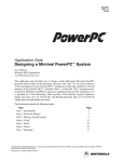
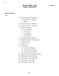
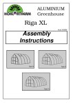
LEARNING
THE ROPES
Ingo Cyliax
Virtex Proto Board
Windows. I’m sure you’ve been there
at one time or another. Someday
they’ll bring out these design tools
under Linux. At least I can dream.
My design environment under
Windows is a mess, but the Linux
environment on my laptop still works
well, enabling me to write this article. This month, I’ll talk about the
Virtex prototyping board I’m using for
the project that got me in trouble—
the Virtual Workbench 300 (VW-300)
from the Virtual Computer Corporation (VCC).
THE BOARD
I
Although Ingo
had originally
planned to follow
up his last article
about multipliers,
he ran into a little
problem. OK, so
it was a big problem. But, that’s to
our benefit.
www.circuitcellar.com/online
The board is a prototyping board
for the Xilinx Virtex series FPGA.
Virtex is Xilinx’s high-end FPGA,
boasting densities of up to one million
gates (more in the Virtex-E). Remind
me to write a piece about how to
compute realistic gate densities in
FPGAs that actually mean something.
Virtex has some nice architectural
features that make it suitable for large
system-on-a-chip designs that include
32-bit processor cores, peripherals,
and high-performance digital signal
processing. There are several types of
memory from SelectRAM that can be
used for small register files (i.e.,
BlockRAM), which are large 4-Kb
originally
planned to follow
my last piece with an
article about how to design with multipliers. Well, to
shorten the story, the software I intended to use in designing some of the
multiplier examples didn’t work.
The longer version of the story is
that, because I was working on a
project, I needed to upgrade my FPGA
design software to the latest and
greatest version. Of course, because it
runs under Windows, this doesn’t
always work the way
you think it will. Such
was the case with the
new installation, so I
decided to downgrade
to the original version.
Unfortunately, it
doesn’t work at all
now. At this point, I
needed to uninstall
both versions by removing all traces of
.dlls, executables, environment variables, and
registry entries, or just
resort to reinstalling
Photo 1—Look at all this neat stuff on such a small board.
CIRCUIT CELLAR ® ONLINE
July 2000
1
Standard
Input Ref.
Voltage
Output Source
Voltage
Termination
Voltage
LVTTL
LVCMOS
PCI
GTL
GTL+
HSTL Class I
HSTL Class III
HSTL Class IV
SSTL3 Class I/II
SSTL2 Class I/II
CTT
AGP
N/A
N/A
N/A
0.8
1.0
0.75
0.75
0.75
1.5
1.125
1.5
1.32
3.3
2.5
3.3
N/A
N/A
1.5
1.5
1.5
3.3
2.5
3.3
3.3
N/A
N/A
N/A
1.2
1.5
1.5
1.5
1.5
1.5
1.125
1.5
N/A
Table 1—Here is a list of all the I/O interfaces that can be supported by Virtex. Each bank’s VIO and VREF power
supplies can be wired to various voltages to help implement these.
RAM modules available on-chip.
BlockRAMs are highly flexible because they can be configured as either
single- or dual-ported memory with
either 1 or 16-bit wide ports. Other
than that, they are of the look-up
table-based CLB architecture, with
plenty of routing resources to connect
them with fast carry support between
adjacent CLBs.
The I/O on Virtex chips is perhaps
the best feature. There are several
banks of I/O, each bank powered by
its own I/O power supply and input
reference voltage. With the appropriate power supplies, various signaling
standards can be implemented. Table
1 shows the supported types.
Of course, the inputs are also 5-V
tolerant if it’s selected and have programmable pull up/pull down and
weak keepers.
To make interfacing even easier,
Virtex has several delay locked loops
(DLL). These can be used to match
internal clock signals to external
clocks in order to reduce the effects of
on/off chip latencies at high clock
rates.
NO RE-FLOW OVEN?
Virtex FPGAs are available in BGA
packages. BGA packages are the package of choice for large chips these
days. Of course, like many new package styles, they are harder to mount
when prototyping or building one-offs.
BGAs have small solder balls on the
bottom of the chip that match up
2
July 2000
with small solder pads on the PCB.
The BGAs are placed on the PCB and
then need to be heated in an oven for
the solder balls to melt and bond with
the solder pads. Of course everyone
has a re-flow oven these days.
Because I don’t have a re-flow oven
handy and didn’t have enough time to
track down a facility that could
handle mounting these packages, I
had to buy a prototype board for this
project. The project, incidentally, was
demonstrating a 32-bit processor core
I developed for my day job. I needed a
Virtex board with a large enough chip
and some external memory pre-wired,
along with a prototyping area for all
the extra stuff.
After searching Optimagic’s web
site, which is great for FPGA resources, I found that the VW-300 fit
the bill, so I ordered one.
Besides the Virtex chip, the VW300 has a lot of memory, a clock, and
connector resources. In addition, there
are LEDs, switches, push buttons, 8digit alphanumeric LED display, and
other neat stuff all on an 5.5″ × 5.5″
board (see Photo 1).
There are three memories on the
VW-300. A 256K × 8-bit flash memory
is used to store startup configuration
for the FPGA. From the factory, it has
a demo that scrolls continual advertising over the alphanumeric display. It’s
nice to have something running so
you can make sure everything is OK
(after you’ve taken it out of the box
and built a power supply). The flash
CIRCUIT CELLAR ® ONLINE
memory can be reprogrammed by
removing it from its socket (it’s
PLCC footprint flash memory) and
programming in a programmer. A
CPLD is used to interface the flash
memory to the Virtex part to perform
Xilinx’s SelectMAP partial
reconfiguration protocol. Because the
CPLD is flash memory-based, I suppose it could be reprogrammed to
perform other functions.
BURST MODE
Besides the flash memory, the
VW-300 also has a 256K × 18-bit
synchronous burst mode fast static
RAM (SBRAM). This is a memory
module normally used for off-chip L2
processor cache and supports burst
mode operations. The cycle time of
the memory installed is 6 ns (166
MHz), which means it can transfer at
a peak rate of over 332 MBps. Because
the SRAM is fast but not too large, an
80-ns 1M x 16 x 4 SDRAM is also
included onboard.
The SRAM and DRAM memories
are devices attached to the FPGA. By
itself, the Virtex does nothing special
with the memories. You would have
to design in a SRAM or DRAM controller into the design loaded on the
FPGA in order to use the memory. In
this project, you can use the SDRAM
as traditional program and data
memory, and the SRAM as fast buffer
memory or cache memory. The Xilinx
web site has cores that can be used to
control burst mode SRAM and
SDRAM in a Virtex design.
Because the Virtex also has on-chip
memory block and small look-up
table-based register files, you can use
a full spectrum of memory hierarchy—from small single- and dualported register files (SelectRAM)
running at sub-nanosecond access
times, to larger memory block
(BLOCKRAM) running at less than 5ns access times. To get to off-chip
memory, you have to figure the latency it takes to get in and out of the
chip and protocol issues, in addition
to the access times of the memory.
For example, to access SBRAM you
have to send the address and wait for
the data to burst out of the memory
sequentially. Although the peak burst
www.circuitcellar.com/online
buffers, which can
diagram of the internal display.
cause fights if not
You can use this display to show a
CLK
properly designed,
hexadecimal representation of inter*W
you can actually
nal registers, assuming you add logic
*E
overheat the chip at to your design to use the display. You
normal operating
can also use it to provide a small
An
SA
temperatures. A
scrolling text console for your project.
temperature sensor
Besides onboard peripherals, there
DQ
D(An)
D(An+1) D(An+2) D(An+4)
can be used to deare a variety of headers and connectect these conditors that can be used to interface exFigure 1—Here you can see the timing diagrams for SBRAM access.
tions and shutdown ternal modules, devices, and logic
rate is fast at 166 MHz, the total access the chip if the temperature exceeds
analyzer inputs to the Virtex on this
time to get four words is at least five
safe levels. I suppose a boring applicaboard. In particular, there are several
cycles. Figure 1 shows timing diagrams tion of a temperature sensor might be
mezzanine connectors for third party
for SBRAM access. In contrast,
to drive a variable speed fan to cool
CODEC modules from Insight, as
BlockRAM works as true random acthe chip optimally.
well as A/D and D/A Omnibus modcess memory, not in burst mode. In any
If you’re building systems on a
ules from Innovative Integration. All
case, with this board you have all the
chip, you might want to use serial
of the I/Os are documented in the
options covered.
communication channels to talk with
user manual, and pin configuration
other computers or a terminal. This
files for the FPGA can be downloaded
board includes a TTL to RS-232 level
MORE OPTIONS
from VCC’s web site.
adapter and a DE-9 connector to perThe VW-300 also has several clockThere are several configurations
ing options. It has two Dallas Semicon- form this. For example, this project
that are supported on this board for
uses an RS-232 port for a background
ductor DS1073 econo-oscillators (100
the Virtex chip. I already mentioned
MHz and 66 MHz). These can be set up debugger type interface.
the flash PROM for doing SelectMAP
Building a UART in FPGA is not
to divide the oscillator frequency by
configuration, and there are jumpers
two, which is the default. In addition to hard. I used to teach students in unand headers for serial PROM, JTAG,
dergraduate hardware labs to do this.
these oscillators, the board has a CyXchecker, and MultiLINX configuraI’ll cover designing UARTs in a later
press ICD2053B adjustable oscillator,
tion. The manual, schematics, and
which can be programmed using a serial article.
datasheet for some of the components
If you like switches and lights, it
protocol either from the FPGA or exterare available on the web site. After
nally. By default, this oscillator runs at has those as well. There is an 8-posiyou have registered for your board,
tion DIP switch and eight surface16 MHz. As if this isn’t enough, there
everything you’d expect from a
mount LEDs you can read and light up prototyping board opens up to you.
is also an extra oscillator site where
with the FPGA. There are also four
you can install your own oscillator
pushbutton switches. However, the
module.
UPON ARRIVAL
Another neat feature is the tempera- neatest peripheral on this board is the
After the board arrived, it became
ture sensor module. This is a Max1617 Infineon IPD2133 8-character 5 × 7
obvious that I was missing somedot matrix
die temperature sensor. The Virtex
provides a diode-based die temperature aphanumeric display.
To the FPGA, the
output that works with this sensor
module. The module converts the tem- display looks like a
small SRAM device.
perature reading and lets you read the
There is an address
temperature through a SMBUS interface, either by the FPGA or externally. bus and a data bus.
The simplest way to
Measuring the die temperature is
use it is to address
useful for several reasons. Because
FPGAs are user programmable, comput- one of the eight digits (address 0–7) and
ing power consumption (and power
write a 7-bit ASCII
dissipation) is complex. During system
testing, you can use the die temperature, code to it. The chip
converts the ASCII
and by knowing the ambient air temcode using an interperature as well as heat transfer coeffinal character ROM
cients for the package and current air
and displays it on the
humidity, you can estimate the power
5 × 7 array for that
consumption and power dissipation.
Also, because this type of Virtex has digit. Not bad. Figure Photo 2—After the voltages were adjusted and everything was hooked up, I was
ready to try it out.
so many flip-flops and internal tristate 2 shows a block
www.circuitcellar.com/online
CIRCUIT CELLAR ® ONLINE
July 2000
3
thing. It turns out that
Ingo Cyliax is the Sr.
OSC
the Virtex chip is a 2.5Hardware Engineer at
V core logic device.
Derivation Systems
Row
Drivers
That means all of the
Inc. (DSI) where he
div 7
div 32
internal logic on this
designs and builds
div 128
chip operates from a
embedded systems and
2.5-V power supply.
hardware components.
ROM
Virtex-E FPGA core
DSI is the leader in
ROM
Chal: RAM
Chal:
word
D Latch
div 3
Decode
RAM
actually runs at 1.8 V.
formally synthesized
decode
Furthermore, most of
FPGA cores and speChal:
decode
the memories and pecializes in embedded
ODC
ripherals work at 3.3 V
Java technology. Ingo
RAM
Chal:
Data bus
decode
and some, like the RShas been writing on
232 converter, run from
various topics ranging
Figure 2—The internal display has an address bus and data bus and provides you with many
a 5-V supply. However,
from real-time operatoptions for use.
there are no onboard
ing systems to nuts
regulators. VCC does have a matching Figure 3. Photo 2 shows what this
and bolts hardware issues for several
looks like.
power supply available for this board
years.
Because the VIN/VOUT differential
that takes care of it all.
Building power supplies isn’t
has to be between 1.5 and 5.75 V, I
SOURCES
rocket science (for the most part), so I
chose a small 5-V switcher that I
Virtual Workbench 300 (VW-300)
figured it shouldn’t be a big deal. Esscrounged up from an old Macintosh.
Virtual Computer Corporation
pecially, because voltage regulators
After carefully adjusting the two volt(818) 342-8294
don’t come in BGA packages, and I
ages (3.3 and 2.5 V), I hooked up evFax: (818) 342-0240
can solder these parts myself. Taking
erything you see in Photo 2 and tried
www.vcc.com
a quick survey however, I discovered
it for the first time. It was nice to see
that 3.3-V regulator ICs are readily
the demo design come up the first
OptiMagic’s Programmable Logic
available and 2.5-V regulators are
time. The compiled project was
Jump Station
harder to come by. I settled on using
downloaded through an Xchecker
Optimagic
Linear Technologies’ LT-1587. These
cable and everything came up as ex(831) 687-0415
devices are available in varied fixed
pected with the board.
Fax: (408) 701-7007
voltages, as well as an adjustable verAlthough I’m typically a strong
www.optimagic.com
sion. I chose the adjustable version
advocate of building your own stuff,
that is available in three terminal TO- it’s nice to be able to use off-the-shelf
220 packages and quickly cobbled up a prototyping boards. Usually when I
power supply on a perforated circuit
build my own boards, I spend a sigboard that matches the schematics in
nificant amount of time debugging
my aspect of the design. In
this case, it was definitely a
5v
timesaver, especially because
it will probably take several
5v
3.3v
attempts to fine-tune any
LT1584
BGA-based home assembly
125
10µF
220µF
techniques. I did figure out
that my kitchen stove
(203.8)
achieves re-flow temperatures
in “clean” mode. Apparently
2.5v
LT1584
the normal thermostatic
control is disabled in this
220µF 125
10µF
mode, and the oven runs up
to its maximum temperature.
(124.3)
At this point, however, I’m
hesitant to try a re-flow with
a $300 FPGA in my kitchen
VOUT = VREF (1+ R2/R1) + Ladj R2
VREF = 1.25 V
oven. If I take on such a task
Ladj. = 55µA
Circuit Cellar, the Magazine for Computer Applications.
in the future, I’ll be sure to
Reprinted by permission. For subscription information,
let you know whether or not
Figure 3—Here you can see a schematic of the power supply I
call (860) 875-2199, [email protected] or
quickly threw together.
I’m successful. I
www.circuitcellar.com/subscribe.htm.
4
July 2000
CIRCUIT CELLAR ® ONLINE
www.circuitcellar.com/online