1
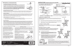
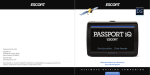
IdealFILM ™ Do-It-Yourself Installation Manual Comfortable Warm Floors Benefits of using RSG Idealfilm • Heats from the floor up for better heat distribution throughout the room • No dust or allergens blown into the room as with forced-air heating • Maintenance free—no furnace or boiler to service • Film contains no materials that are harmful to the environment • Electromagnetically safe • Fast, easy installation Contents 2 Important Notes 3 What’s in the box 3 Additional materials required 3 Tools required 4 Planning the job 6 Installation 13 Operation 13 Customer assistance 13 Installation Certificate Important notes Read through this entire manual before starting installation. • May be installed under laminate, engineered wood or approved hardwood floors. See flooring manufacturer’s specifications and instructions. • Installation must be performed by a qualified person in accordance with national and local codes and standards. • Each thermostat requires a dedicated circuit at the breaker box. • IdealFilm under-floor heating systems must be protected by a Ground Fault Circuit Interrupter (GFCI). • All electrical connections must be made by a licensed electrician. • Must not be installed in damp or wet areas as defined by the National Electrical Code. • Do not fold or wrinkle the heating film, walk on it unnecessarily, or drop heavy or sharp objects on it. • Never overlap the heating film. • Do not install electrical wires or pipes in the floor with the film. • Be sure underlayment contains no cellulose. • Install film only when room temperature is above freezing. • Leave a 6-inch space between film and fireplaces, chimneys, or hot water pipes. • Never use any type of insulation material on top of the heating film. Failure to follow these instructions may result in fire, electrical shock, property damage, personal injury, or death. 2 RSG IdealFilm What’s in the box • Radiant heating film • Connecting wire—14 gauge, stranded, double insulated (3 ft. of black and 3 ft. of white) • Connector clips (4) • Insulating tape, 65 mil mastic (3 pieces, 2” x 4”) Additional materials required • Wire connectors/wire nuts (if necessary) • 2-gang electrical junction box and cover (if necessary) • Flexible conduit for film to thermostat connection (if necessary) • Underlayment pad—1/4 in. • Thermostat, 15 Amp with 15mA ground fault circuit interrupter (GFCI) and floor temperature sensor—available from RSG • 12 gauge stranded THHN wire (from film to thermostat) • Electrical tape • 12-2 G NM cable from (from thermostat to breaker box) • Polyethylene vapor barrier, 6 mil (only if installation is on concrete) • Duct tape Tools required • Special crimping tool for connector clips • Wire cutter/stripper • Screwdrivers (straight and phillips) • Utility knife • Scissors • Hammer • Wood chisel • Pliers • Drywall jab saw • Multimeter • Measuring tape Installation Manual 3 Planning the job This drawing shows the order of installing the materials on the floor: Flooring Heating Film Underlayment Moisture Barrier (on concrete only) Subfloor 1. Draw an installation plan Sketch a plan showing how the film will be installed. At least 75% of the floor should be covered with film for best heating efficiency. Note that the film may be cut to size across its width (in clear areas) but not along its length. Do not install film under built-in cabinets, in small closets (walk-ins are okay), or under other structures that do not have air circulation space under them. Leave 6 inches between film and wax toilet rings. Locate the thermostat on a wall away from other heat sources and out of direct sunlight. Here’s a sample installation floor plan sketch: 12' Built-in Bookcase Sensor Thermostat 4 RSG IdealFilm 10' Because of the layout of the room in this drawing, the film panels are about 1 inch apart and about 2 inches from the walls. Your panels may be closer or farther apart but should never overlap. In the drawing the film is laid out so that the ends are at the wall where the thermostat is located. This arrangement requires less wire and is more convenient for thermostat connection. In some cases it may be necessary to trim the length to fit. Film may be cut only in the 1 1/4 -inch clear areas between the carbon heating elements. 2.Check the current draw Make sure that the total current draw of the heating film in your layout does not exceed the thermostat’s limit of 15 amps. Each linear foot of film draws .2 amps—if your installation contains no more than 75 linear feet of film the installation will be within the 15-amp limit of the thermostat. If your installation contains between 75 and 150 linear feet of film, you will be required to use a 240-volt circuit. Any installation of more than 150 linear feet will require a second thermostat. Installation Manual 5 Installation A NOTE ON ELECTRICAL WORK Because each installation is unique, this manual gives only a general description of electrical connections. The licensed electrician that does the electrical hookups will make final decisions based on the individual circumstances of your installation and applicable national and local codes. 1.Mark the position of the thermostat Place it on the wall about 5 feet above the floor. Make sure that it is not near any other heat sources and is out of direct sunlight. If you plan to use a junction box in the installation, position it below the thermostat and about 18 inches above the floor. 2.Clean the floor thoroughly Sweep or vacuum floor to remove any foreign material that could damage the underlayment pad or film. Smooth out any imperfections in the sub floor and remove nails protruding above the surface. 3. Install polyethylene vapor barrier (This step is necessary only if the subfloor is concrete.) Lay vapor barrier over entire floor leaving 1-inch space at the edges for taping. Overlap sheets by 4 inches and tape entire seam with duct tape. Tape to floor around the edges of the room. 4.Install the underlayment pad Lay out the pad material and cut it to fit with a gap of 1 inch between the pad and the wall. At the wall with the thermostat, leave a gap of 2 inches to act as a channel for the wires to run in. Make sure that the pad is smooth and flat, then tape it to the subfloor along the wall. Tape the joints where sections butt together. Cover the entire finished-floor area. 6 RSG IdealFilm 5. Install the heating film Remove shoes and work in stocking feet when installing film. Be careful not to drop objects on the film. Roll out the film with the bright copper strips facing down. If you need to trim the length of the film, cut in the 1 1/4 -inch-wide clear areas only—do not cut into the black carbon strips. Film panels may be butted together or have some space between them depending on the layout of the room—they should never overlap! Use duct tape to fasten the film panels to the pad and/or to each other. 6. Attach the wires to the film Here’s a sample wiring diagram: To breaker Thermostat Sensor Note that the film panels are wired in parallel. Plan your connections to allow for the most direct routing of the wires from the film to the thermostat. Installation Manual 7 Strip the insulation from one end of a 3-foot length of 14 gauge stranded black wire. The wire is double insulated— be sure to strip both layers of insulation. Use only the crimping tool designed specifically for this type of connector. Using any other type of tool could result in loose connections. Insert the barrel of the connector into the crimping tool so that the “W” of the tool presses on the split side of the barrel. The tool will not release until there is sufficient pressure on the crimp. After crimping, test the wires to be sure they are tight in the connector. If only one wire is to be crimped in the connector, strip 1/2 inch of insulation and double the wire over into a “U” shape before crimping. If two wires are to be crimped together, strip 1/4 inch of insulation from each wire and insert them into the connector together. Place the connector over the copper strip on a corner of the film and crimp it so that the teeth on the connector bite into the copper strip. Crimp the connector firmly from both the left and right sides. The crimping tool will not release until there is sufficient pressure on the crimp. 8 RSG IdealFilm Run the other end of the wire to the corresponding corner on the next film panel to the right—allow a little slack. Shorten the wire if necessary and strip the end. Also strip the insulation from the end of another piece of black wire. Crimp both wires into a connector clip and crimp the flat end of the clip to the copper strip on the left corner. Make these connections between the film panels until a left corner of each panel is connected to the left corner of the next panel with the black wire. 14 gauge black wire 12 gauge wire to thermostat Now go back to the film panel you started with and connect the right corners in the same way with white wire. At the last corner connect a piece of 12 gauge wire that is long enough to easily reach the junction box or thermostat. 12 gauge wire to thermostat 14 gauge white wire Installation Manual 9 7.Check the total film resistance When all of the wires have been attached to the film, check the total resistance (ohms) to be sure that the connections are tight and that there is no damage to the film. Touch the ohmmeter leads to the 12 gauge wires that will go from the film to the thermostat and record the reading. Each piece of film is labeled with its resistance specification in ohms. The longer the piece of film, the less the resistance. Add the ohms on the labels for all of the pieces of film in your installation. The ohmmeter reading you recorded should be within 10–15% (plus or minus) of the total. If you have cut any pieces of film to a shorter length, the resistance for that piece will be more than what’s listed on the label. If the resistance is not within specifications, check all of the wire-to-film connections to be sure they are tight and make sure that the film is not damaged. 8. Insulate film-to-wire connections Cut 2-inch-wide mastic insulating tape into 2-inch squares. Apply a square of tape to both the top and bottom side of each wire connection and press them together firmly to form a tight seal. In the same way, use the mastic tape to cover all of the bare ends of each copper strip that do not have wire connections. 10 RSG IdealFilm 9. Cut wire channels in the underlayment mat Channels for the wires and connectors must be cut in the underlayment mat. Use a utility knife to cut the channels, place wires into channels, and cover the channels with duct tape. 10. Cut a notch in the drywall for the wires Use a hammer and chisel to cut a notch in the drywall and wall base plate so that there is room for wires to go from the floor to the thermostat. 11. Install the floor temperature sensor This sensor prevents the floor from overheating. Position the sensor between the film panels near the junction box and about 20-inches from the wall. Cut a channel in the underlayment pad so that the sensor and its wires are below the level of the pad. Run the wire from the sensor to the thermostat and tape it to the pad and the floor. Installation Manual 11 12. Install the thermostat Refer to thermostat manufacturer’s installation instructions. Wires running within the walls must be NM sheathed cable or be protected with conduit. 13. Install the floor covering Read and follow floor covering manufacturer’s instructions for installation of their product. 14.Place warning labels On the wall near the thermostat: Warning Electric wiring and heating panels installed below floor. Do not penetrate floor with nails, screws or other objects. In the breaker box near the breaker for the heated floor: Caution This circuit is dedicated to an under-floor heating system. Refer to installation booklet. 12 RSG IdealFilm Operation When the finished floor has been installed, allow time for the flooring to become acclimated to the room temperature and humidity before turning on the power (see flooring instructions). Turn on the electrical power at the breaker box. Follow thermostat manufacturer’s instructions to set floor and air temperatures. Do not use beanbag chairs, mattresses, solid-bottom chests, or other large solid items that would trap heat in the floor and cause it to overheat. Do not use nails or screws in the floor from above or below (in the basement or crawl space). Warranty RSG IdealFilm is guaranteed to be free of manufacturing defects for a period of 15 years from the date of purchase. The warranty is subject to the following conditions: • All electrical connections must be made by a licensed electrician. • Proof of purchase and Installation Certificate must be submitted with warranty claim. • Warranty covers replacement of defective materials only and does not cover labor costs, replacement of floor covering, or secondary charges related to the replacement of floor covering. • Warranty does not cover defects resulting from incorrect installation or damage caused by others. Installation Certificate Date of purchase (attach receipt)______________________________________________ Date of installation___________________________________________________________ Voltage_____________________________________________________________________ Linear feet of film____________________________________________________________ Measured resistance (ohms)___________________________________________________ Thermostat brand___________________________ Model number____________________ Electrical contractor__________________________________________________________ Electrician license number_____________________________________________________ Installation Manual 13 Customer assistance At Radiant Systems Group we stand ready to assist you in the planning, ordering and installation of RSG IdealFilm. For help call 855-265-5450 between 8:00 am and 5:00 pm eastern time. Radiant Systems Group, LLC 3130 Sovereign Drive, Suite A Lansing, MI 48911 Technical assistance: 855-265-5450 Sales: 855-265-5455 Radiant Systems Group, LLC is the North American distributor for heating film manufactured in South Korea