1
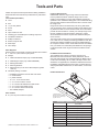
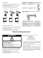
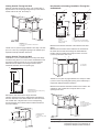
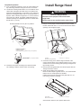
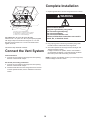
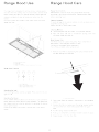
Table of Contents
APPROVED FOR RESIDENTIAL APPLIANCES
FOR RESIDENTIAL USE ONLY
READ AND SAVE THESE INSTRUCTIONS
Important Safety Notice ..........................................................3
Tools and parts ........................................................................4
Location Requirements ......................................................4
Product Dimensions ...........................................................4
Venting Requirements ........................................................5
Venting Methods ................................................................6
Calculating Vent System Length ........................................6
Electrical Requirements...........................................................6
Installation Instructions ..........................................................7
Prepare Location.................................................................7
Install range hood.....................................................................9
Connect the Vent System....................................................10
Complete Installation...........................................................10
Range Hood Use.......................................................................11
Range Hood Care......................................................................11
Available Accessories..............................................................12
Warranty.....................................................................................13
PLEASE READ ENTIRE INSTRUCTIONS BEFORE PROCEEDING.
INSTALLATION MUST COMPLY WITH ALL LOCAL CODES.
IMPORTANT: Save these Instructions for the Local Electrical
Inspector’s use.
INSTALLER: Please leave these Instructions with this unit for
the owner.
OWNER:Please retain these instructions for future
reference.
Safety Warning:Turn off power circuit at service panel and lock
out panel before wiring this appliance.
Requirement 120 VAC, 60 Hz. 15 or 20 A Branch Circuit
IMPORTANT SAFETY INSTRUCTIONS
WARNING: TO REDUCE THE RISK OF A RANGE TOP
GREASE FIRE:
■■ Never leave surface units unattended at high settings.
Boilovers cause smoking and greasy spillovers that may
ignite. Heat oils slowly on low or medium settings.
■■ Always turn hood ON when cooking at high heat or when
flambeing food (i.e. Crepes Suzette, Cherries Jubilee,
Peppercorn Beef Flambé).
■■ Clean ventilating fans frequently. Grease should not be
allowed to accumulate on fan or filter.
■■ Use proper pan size. Always use cookware appropriate for
the size of the surface element.
WARNING: TO REDUCE THE RISK OF INJURY TO
PERSONS IN THE EVENT OF A RANGE TOP GREASE FIRE,
OBSERVE THE FOLLOWING:a
■■ SMOTHER FLAMES with a close fitting lid, cookie sheet, or
metal tray, then turn off the burner. BE CAREFUL TO
PREVENT BURNS. If the flames do not go out
immediately, EVACUATE AND CALL THE FIRE
DEPARTMENT.
■■ NEVER PICK UP A FLAMING PAN - you may get burned.
■■ DO NOT USE WATER, including wet dishcloths or towels a violent steam explosion will result.
■■ Use an extinguisher ONLY if:
-You know you have a class ABC extinguisher, and you
already know how to operate it.
– The fire is small and contained in the area where it
started.
– The fire department is being called.
– You can fight the fire with your back to an exit.
WARNING: TO REDUCE THE RISK OF FIRE, ELECTRIC
SHOCK, OR INJURY TO PERSONS, OBSERVE THE
FOLLOWING:
■■ Use this unit only in the manner intended by the
manufacturer. If you have questions, contact the
manufacturer.
■■ Before servicing or cleaning the unit, switch power off at
service panel and lock the service disconnecting means to
prevent power from being switched on accidentally. When
the service disconnecting means cannot be locked, securely
fasten a prominent warning device, such as a tag to the
service panel.
■■ Installation work and electrical wiring must be done by
qualified person(s) in accordance with all applicable codes
and standards, including fire-rated construction.
■■ Sufficient air is needed for proper combustion and
exhausting of gases through the flue (chimney) of fuel
burning equipment to prevent backdrafting. Follow the
heating equipment manufacturer’s guideline and safety
standards such as those published by the National Fire
Protection Association (NFPA), the American Society for
Heating, Refrigeration and Air Conditioning Engineers
(ASHRAE), and the local code authorities.
■■ When cutting or drilling into wall or ceiling; do not damage
electrical wiring and other utilities.
■■ Ducted fans must always be vented outdoors.
CAUTION: For general ventilating use only. Do not use to
exhaust hazardous or explosive materials and vapors.
CAUTION: To reduce risk of fire and to properly exhaust air,
be sure to duct air outside - do not vent exhaust air into
spaces within walls or ceilings, attics or into crawl spaces, or
garages.
Based on “Kitchen Fire Safety Tips” published by NFPA.
■■ WARNING: To reduce the risk of fire or electrical shock,
do not use this fan with any solid-state speed control
device.
a
WARNING: TO REDUCE THE RISK OF FIRE, USE ONLY
METAL DUCTWORK
READ AND SAVE THESE INSTRUCTIONS
3
Tools and Parts
Gather the required tools and parts before starting installation.
Read and follow the instructions provided with any tools listed
here.
Tools needed (all models)
Location Requirements
IMPORTANT: Observe all governing codes and ordinances.
Have a qualified technician install the range hood. It is the
installer’s responsibility to comply with installation clearances
specified on the model/serial rating plate. The model/serial rating
plate is located inside the liner behind the filter on the left wall of
the range hood.
Range hood location should be away from strong draft areas,
such as windows, doors, and strong heating vents.Cabinet opening dimensions that are shown must be used. Given dimensions
provide minimum clearance. Consult your cooktop/ range manufacturer installation instructions before making any cutouts.
Grounded electrical outlet is required. See “Electrical Requirements” section.
The range hood is factory set for vented installations through the
roof or wall. For non-vented (recirculating) installations see “NonVented (recirculating) Installation Through the Soffit/Cabinet” in
the “Prepare Location” section. Recirculation Kit Part is available
from your dealer or an authorized parts distributor. All openings
in ceiling and wall where range hood will be installed must be
sealed.
■■ Level
■■ Drill
■■ ¹⁄8” (3.0 mm) drill bit
■■ Pencil
■■ Pliers
■■ Tape measure or ruler
■■ Caulking gun and weatherproof caulking compound
■■ Flat-blade screwdriver
■■ Phillips screwdriver
■■ Saber or keyhole saw
■■ Metal snips
■■ Vent clamps
Parts Supplied
Remove parts from packages. Check that all parts are included.
■■ 1 - 30” x 12” (76.2 x 30.5 cm) face panel
For Mobile Home Installations
The installation of this range hood must conform to the
Manufactured Home Construction Safety Standards, Title 24
CFR, Part 328 (formerly the Federal Standard for Mobile Home
Construction and Safety, title 24, HUD, Part 280) or when such
standard is not applicable, the standard for Manufactured Home
Installation 1982 (Manufactured Home Sites, Communities and
Setups) ANSI A225.1/NFPA 501A, or latest edition, or with local
codes.
■■ Damper
■■ 2 - 40W incandescent lamps (only model EAS428SS)
■■ 2 - 50W halogen lamps (only model EPR628SS)
■■ 2 - Metal grease filters
■■ 2 - Mounting brackets
■■ 2 - Metal spacers (for use when cabinet depth is greater
than 12”)
■■ Hardware package. Includes:
•
•
•
•
•
•
•
•
•
Product Dimensions
Installation Instructions and Use and Care Guide
8 - metal washers
8 - plastic washers
10 - 4.5 x 13 mm wood screws
2 - 4.2 x 15 mm machine screws
4 - 3.5 x 9.5 mm flat-head sheet metal screws
8 - 4.2 x 19 mm sheet metal screws
6 - 3.5 x 9.5 mm sheet metal screws
T10 TORX®† adapter
Parts needed
■■ 6” (15.2 cm) round metal vent system
I* - Metallic spacers
Spacers has to be installed
and used when cabinet depth
is greater than 12”.
I*
I*
AAR428SS / AGR628SS range hood models
Dimension
DIM A
DIM B
26” (66 cm)
DIM C
1 ⅛” (2.9 cm)
DIM D
10 ¾” (27.3 cm)
DIM E
9 ½” (24.2 cm)
DIM F
†®TORX is a registered trademark of Saturn Fasteners, Inc.
4
281⁄4” (71.8 cm)
⁄16” (.85 cm)
5
DIM G
14 9⁄16” (37 cm)
DIM H
6” (14.8 cm)
DIM I
½” (1.27 cm)
Installation Clearances
VENTING REQUIREMENTS
■■ Vent system must terminate to the outdoors, except for no
vented (recirculating) installations.
■■ Do not terminate the vent system in an attic or other enclosed
area.
■■ Do not use a 4” (10.2 cm) laundry-type wall cap.
■■ Use metal vent only. A rigid metal vent is recommended.
Plastic or metal foil vent is not recommended.
■■ The length of the vent system and number of elbows should
be kept to a minimum to provide efficient performance.
For the most efficient and quiet operation:
■■ Use no more than three 90° elbows.
■■ Make sure there is a minimum of 24” (61.0 cm) of straight
vent between the elbows if more than 1 elbow is used.
■■ Do not install 2 elbows together.
■■ The vent system must have a damper.
■■ Use clamps to seal all joints in the vent system.
■■ Use caulking to seal exterior wall or roof opening around the
cap.
■■ The size of the vent should be uniform.
Cold weather installations
A. 12” (30.5 cm) min. upper
cabinet height
B. 30” (76.2 cm)
cabinet opening width*
C. 24” (61 cm) min. 36” (91.4 cm)
suggested max. bottom of
cabinet to cooking surface
An additional back draft damper should be installed to minimize
backward cold air flow and a thermal break should be installed to
minimize conduction of outside temperatures as part of the vent
system. The damper should be on the cold air side of the thermal
break.
The break should be as close as possible to where the vent
system enters the heated portion of the house.
D. 12” (30.48 cm) cabinet
opening depth*
E. 15” (38.1 cm) min. clearance
upper cabinet to countertop
F. 36” (91.4 cm) base cabinet
height
Makeup air
Local building codes may require the use of makeup air systems
when using ventilation systems with greater than specified CFM
of air movement. The specified CFM varies from locale to locale.
Consult your HVAC professional for specific requirements in your
area.
For gas range installation: Mount this hood so that the bottom
edge is at minimum 27”(68,5 cm) above the cooking surface.
For electric range installation: mount this hood so that the bottom
is not less than 24”(61 cm).
*NOTE: This range hood is set to 30” (76.2 cm) cabinet width x
12” (30.5 cm) deep cabinets.
5
Venting Methods
Vent Piece
6” (15.2 cm)
This range hood is factory set for venting through the roof or
through the wall. You can apply the recirculating venting method
by purchasing the Recirculation Kit.
The vent system needed for installation is not included.
A 6” (15.2 cm) round vent system is recommended.
45° elbow
2.5 ft
(0.8 m)
90° elbow
5.0 ft
(1.5 m)
Roof Venting
Wall Venting
Recirculating
Example Vent System
90° elbow
6 ft (1.8 m)
Wall cap
2 ft (0.6 m)
Maximum Recommended Length
A. 6” (15.2 cm) vent through the roof
B. Roof cap
A. 6” (15.2 cm) vent
through the wall
B. Wall cap
A. 6” (15.2 cm) vent
through the cabinet
B. Round recirculating grid
Calculating Vent System Length
= 35 ft (10.7 m)
1 - 90° elbow
= 5.0 ft (1.5 m)
1 - wall cap
= 0.0 ft (0.0 m)
9 ft (2.8 m) straight
= 9.0 ft (2.8 m)
Length of 6” (15.2 cm) system
= 14.0 ft (4.3m)
The recommended vent system is 6” (15.2 cm) round vent with a
maximum length of 35 ft (10.7 m). For the best performance, use
no more than three 90° elbows.
To calculate the length of the system, add the equivalent feet
(meters) for each of the vent pieces used in the system.
Electrical Requirements
A copy of the above code standards can be obtained from:
National Fire Protection Association
1 Batterymarch Park
Quincy, MA 02169-7471
CSA International
8501 East Pleasant Valley Road
Cleveland, Ohio 44131-5575
WARNING
Plug into a grounded 3 prong outlet.
Do not remove ground prong.
Do not use an adapter.
Do not use an extension cord.
Failure to follow these instructions can result in
death, fire, or electrical shock.
■■ A 120 volt, 60 Hz, AC only, 15- or 20-amp, fused electrical
circuit is required. A time-delay fuse or circuit breaker is also
recommended. It is recommended that a separate circuit
serving only this range hood be provided.
■■ This range hood is equipped with a power supply cord having
a 3 prong grounding plug.
■■ To minimize possible shock hazard, the cord must be
plugged into a mating, 3 prong, grounding-type outlet,
grounded in accordance with local codes and ordinances. If a
mating outlet is not available, it is the personal responsibility
and obligation of the customer to have the properly grounded
outlet installed by a qualified electrician.
IMPORTANT: The range hood must be electrically grounded in
accordance with local codes and ordinances, or in the absence
of local codes, with the National Electrical Code, ANSI/NFPA 70
(latest edition) or Canadian Electrical Code, CSA C22.1
No. 0-M91 (latest edition).
If codes permit and a separate ground wire is used, it is
recommended that a qualified electrical installer determine that
the ground path is adequate.
6
■■ The grounded 3 prong outlet is to be located inside the
cabinet above the range hood at a maximum distance of
337⁄16” (85.0 cm) from where the power cord exits the hood.
The grounded 3 prong outlet must be accessible after
installation of the range hood. See illustration.
GROUNDING INSTRUCTIONS
■■ For a grounded, cord-connected range hood:
This range hood must be grounded. In the event of an
electrical short circuit, grounding reduces the risk of electric
shock by providing an escape wire for the electric current.
This range hood is equipped with a cord having a grounding
wire with a grounding plug. The plug must be plugged into an
outlet that is properly installed and grounded.
WARNING: Improper grounding can result in a risk of electric
shock.
Consult a qualified electrician if the grounding instructions are
not completely understood, or if doubt exists as to whether
the range hood is properly grounded.
Do not use an extension cord. If the power supply cord is too
short, have a qualified electrician install an outlet near the
range hood.
33 7⁄16 (85 cm)
SAVE THESE INSTRUCTIONS
Installation Instructions
Prepare Location
Cut out dimensions (without spacers)
■■ It is recommended that the vent system be installed before
the range hood is installed.
⁄4”
3
■■ Before making cutouts, make sure there is proper clearance
within the ceiling or wall for vent fittings.
1
⁄2”
■■ Making the cutout to the bottom of the cabinet may be easier
to do prior to mounting the cabinet to the wall.
107⁄8”
(27.62cm)
1. Disconnect power.
2. Determine which venting method to use: roof, wall, or non
vented.
3. Select a flat surface for assembling the range hood. Place
covering over that surface.
283⁄8” (72 cm)
WARNING
5. Complete cabinet preparation following the instructions for
your type of venting. Determine venting cutout locations and
cut out vent openings in the cabinets, walls and/or soffit.
Excessive Weight Hazard
Use two or more people to move and install
range hood.
Failure to do so can result in back or other injury.
4. Using 2 or more people, lift range hood onto covered surface.
Range Hood Cabinet Cutout
Use a saber saw or keyhole saw to cut out the cabinet
bottom inside the cabinet frame.
NOTE: Frameless type cabinets require ¾” (1.9 cm) front lip
in the cabinet bottom. A ¾” (1.9 cm) thick filler strip (not
supplied) may be required for some types of cabinets. (See
Step 3 in the “Install Range Hood” section).
7
Venting Outside Through the Roof
Non-Vented (recirculating) Installation Through the
Soffit/Cabinet
Measure and mark the lines as shown. Use a saber saw or
keyhole saw to cut an opening through the top of the cabinet
and the roof for the vent. Go to Step 3.
B
A
B*
A
A
G
G
C
B
C
F
D
F
D
I
E
E
H
D
A. Ceiling
B. Vent cover
C. Soffit
D. 6” (15.2 cm) vent
E. Range hood
A. Cutout
B. 6¼” (15.9 cm)*
C. 7¾” (19.7 cm) centerline to cabinet front
D. Centerline
F. Cabinet
G.Wall
H. 12” (30.5 cm) min. cabinet height
I. 17” (43.2 cm) min. vent cover height
Measure and mark the centerline of the cabinet to the soffit
above.
Measure from the bottom of the cabinet to the centerline of
the where the vent will come through the soffit. Mark the
location and use a saber saw or keyhole saw to cut a 5¾”
(14.6 cm) hole for the vent cover.
*NOTE: For 12” (30.5 cm) high cabinets a 6¼” deep x 8” wide
(14.6 cm x 20.3 cm) rectangular opening in the cabinet top is
required for damper transition clearance.
Venting Outside Through the Wall
A
Install the 6” (15.2 cm) vent transition to the top of the range
hood liner using two 3.5 x 9.5 mm screws. Assemble the vent
duct that you will use over the 6” (15.2 cm) vent transition.
Measure from the bottom of the range hood liner to the
horizontal centerline of the vent opening (A).
B
A. Vent cover
B. Centerline
B
A
*NOTE: For 12” (30.5 cm) high cabinets a 6¼” deep x 8” wide
(14.6 cm x 20.3 cm) rectangular opening in the cabinet top is
required for damper transition clearance.
C
Measure and mark the centerline location for the cutout in the
cabinet top. Use a saber saw or keyhole saw to cut an
opening for the vent.
A. Measurement A
B. Horizontal centerline of vent opening
C. Range hood liner
B
A
Remove the vent duct from the range hood liner.
Transfer measurement A to the cabinet back wall. Measure
from the underside of the cabinet. Mark the cutout as shown.
Use a saber saw or keyhole saw to cut a round opening
through the back of the cabinet and the exterior wall for the
vent. Go to Step 3.
C
A. Cutout
B. See chart below
C. 7¾” (19.7 cm) centerline to cabinet front
D. Centerline
D
A. Measurement A
B. Centerline
C. 6¼” (15.9 cm) round
cutout
A
B
C
8
Cabinet Height
Hole Shape and Size
12” (30.5 cm)
A 6¼” deep x 8” wide (15.9 cm x 20.3 cm)
rectangular opening in the cabinet top is
required for damper transition clearance.
Install Range Hood
Complete Preparation
3. If not yet attached, install the 6” (15.2 cm) vent transition the
top of the range hood liner using two 3.5 x 9.5 mm screws.
4. Locate side mounting bracket flush 1 cm to the bottom of the
cabinet side and against the inside of the front cabinet face.
Orient the bracket depending on the width of your cabinet as
depicted in the diagrams below. Drill ⅛” (3 mm) pilot holes in
6 places, attach a bracket using three 4.5 x 13 mm screws to
each side of the cabinet, and tighten. Additional washers in
hardware package are supplied as spacers for cabinet walls
thinner than ½” (13 mm).
WARNING
Excessive Weight Hazard
Use two or more people to move and install
range hood.
Failure to do so can result in back or other injury.
Bracket Orientation for 30” (76.2 cm) Cabinet
1. Using 2 or more people, lift the hood liner into its mounted
location. Attach with four 4.2 x 19 mm screws into the slotted
openings. Do not tighten screws.
B
A
C
D
A
A. 30” (76.2 cm) cabinet
B. Screws - 4.5 x 13 mm (6)
C.Washers (optional)
D. Mounting bracket (2) (position for 30” [76.2 cm] cabinet)
B
C
Move the bracket ⁄16” (1 cm) from the bottom
side of the cabinet
6
A.Cabinet
B.Hood liner canopy assembly
C. Screws - 4.2 x 19 mm (8)
2. Center the canopy in the cabinet. Align the bottom of the
canopy with the bottom of the cabinet. Install four 4.2 x 19 mm
screws into the round mounting plate openings and tighten all
(8) mounting screws.
5. Install the vent system according to the method needed.
Use caulking to seal the exterior wall or roof opening.
3. Remove the metal grease filters from the face panel. See the
“Range Hood Care” section.
4. Attach the face plate to the hood insert.
NOTE: If cabinet depth is greater than 12”, it is recommended
that the two 1/2” metal spacers are installed.
Install to front and rear sides of the face plate with 3.5 x 9.5
mm screws as shown in drawing.
C
A
C
B
A.Face Panel
B.Front and rear spacer
C. Screws - 3.5 x 9.5 mm (4)
See instruction below for your specific cabinet size.
9
Complete Installation
1. Replace grease filters. See the “Range Hood Care” section.
B
WARNING
C
D
Electrical Shock Hazard
Plug into a grounded 3 prong outlet.
Do not remove ground prong.
Do not use an adapter.
Do not use an extension cord.
Failure to follow these instructions can result in
death, fire, or electrical shock.
A
A. Screws - 3.5 x 9.5 mm flat-head (4)
B. Face plate (30” x 12” [76.2 cm x 30.5 cm] shown)
C. Cabinet (30” x 12” [76.2 cm x 30.5 cm] shown)
D. Screws - 4.2 x 15 mm truss-head (2)
For cabinet size - 30” x 12” (76.2 cm x 30.5 cm)
Attach the 30” x 12” (76.2 cm x 30.5 cm) face panel (supplied
with range hood) to the hood liner using four 3.5 x 9.5 mm
flat-head screws and two 4.2 x 15 mm truss head screws.
Tighten to secure.
2. Plug 3-prong power cord into a grounded 3-prong outlet
located inside the cabinet above the range hood.
Connect the lamp electrical connector.
Connect the Vent System
Vented Installations
1. Connect the vent system to the range hood vent opening.
Seal the connection with clamps.
3. Check the operation of the range hood fan and light. See
“Range Hood Use” section.
If range hood does not operate, check to see whether a
circuit breaker has tripped or a household fuse has blown.
Disconnect power and check wiring connections.
NOTE: To get the most efficient use from your new range hood,
read the “Range Hood Use” section.
Non-Vented (recirculating) Installations
1. Connect the vent system to the range hood vent opening.
Seal the connection with clamps.
2. Install charcoal filters. See the “Range Hood Care” section.
To order replacement kits, see the “Assistance or Service”
section.
10
Replacing the halogen lamp (ARG628SS models)
CAUTION: Before replacing the lamps, disconnect power off
to prevent from being switched on accidentally.
Turn off the range hood and allow the halogen / incandescent
lamp to cool. To avoid damage or decreasing the life of the new
bulb,donottouchbulbwithbarefingers.Replacebulb,usingtissue or wearing cotton gloves to handle bulb.
If new lamps do not operate, make sure the lamps are inserted
correctly before calling service.
Available Accessories
Recirculating Kit
If it is not possible to vent cooking fumes and vapors to the
outside,therangehoodcanbeusedinthenon-vented
(recirculating)version,usingacharcoalfilter.RecirculationKit
model number KIT07770 is available from The Home Depot
as a separate purchase..
A
A
1. Disconnect power.
2. Push up on the lens and turn it counterclockwise.
B
3. Remove the bulb and replace it with a 120-volt, 50-watt
maximum halogen bulb with a GU10 base. Turn it clockwise
to lock it into place.
G
G
B
C
4. Repeat steps 2-3 for the other bulb if needed.
5. Reconnect power.
F
D
F
I
E
D
E
H
A. Ceiling
B. Vent cover
C. Soffit
D. 6” (15.2 cm) vent
E. Range hood
F. Cabinet
G.Wall
H. 12” (30.5 cm) min. cabinet height
I. 17” (43.2 cm) min. vent cover height
NOTE: 12” (30.5 cm) high cabinets without a soffit may allow the
6” vent and vent cover to be seen.
Replacing the incandescent lamps (AAR428SS models)
1. Use a Phillips # 2 screw driver to remove the lamp cover.
Remove it carefully from its housing.
The charcoal filters cannot be cleaned. They must be replaced.
Cover the grill that protects the suction motor with the carbon
filter so that the slots on the filter correspond to the pins on
the sides of the motor protection grill.
Turn the carbon filter clockwise to block them (bayonet fixing).
The charcoal filters should be replaced every 4-6 months
(depending on hood usage).
2. Remove the damaged lamp bulb (turn counter clockwise) and
replace it with a new bulb. E12 Philips Lamp 120V, 40W.
NOTE: DO NOT rinse, or put charcoal filters in an automatic
dishwasher.
Reconnect power.
Extension Liner Kit
• 30” wide x 17” or 20” deep liner is available for both AAR428SS
and AGR628SS which provides complete protection of
the
cabinets (modelnumberKIT02773).
• 36” wide x 17” or 20” deep liner is available for both AAR428SS
and AGR628SS which provides complete protection of
the cabinets(modelnumberKIT02774).
See Liner installation instructions for more detail.
12
WARRANTY
ELICA North America
TWO-YEAR LIMITED WARRANTY
TO OBTAIN SERVICE UNDER WARRANTY
Owner must present proof of original purchase date. Please keep a copy of your dated proof of purchase (sales slip) in order to
obtain service under warranty.
PARTS AND SERVICE WARRANTY
For the period of two (2) year from the date of the original purchase, Elica will provide free of charge, non consumable parts or
components that failed due to manufacturing defects. During these two (2) year limited warranty, Elica will also provide free of
charge, all labor and in-home service to replace any defective parts.
WHAT IS NOT COVERED
•
•
•
•
•
•
•
•
•
•
Damage or failure to the product caused by accident or act of God, such as, flood, fire or earthquake.
Damage or failure caused by modification of the product or use of non-genuine parts.
Damage or failure to the product caused during delivery, handling or installation.
Damage or failure to the product caused by operator abuse.
Damage or failure to the product caused by dwelling fuse replacement or resetting of circuit breakers.
Damage or failure caused by use of product in a commercial application.
Service trips to dwelling to provide use or installation guidance.
Light bulbs, metal or carbon filters and any other consumable part.
Normal wear of finish.
Wear to finish due to operator abuse, improper maintenance, use of corrosive or abrasive cleaning products/pads and oven
cleaner products.
WHO IS COVERED
This warranty is extended to the original purchaser for products purchased for ordinary residential use in North America (Including
the United States, Guam, Puerto Rico, US Virgin Islands & Canada).
This warranty is non-transferable and applies only to the original purchaser and does not extend to subsequent owners of the
product. This warranty is made expressly in lieu of all other warranties, expressed or implied, including, but not limited to any
implied warranty of merchantability or fitness for a particular purpose and all other obligations on the part of Elica North America,
provided, however, that if the disclaimer of implied warranties is ineffective under applicable law, the duration of any implied
warranty arising by operation of law shall be limited to two (2) year from the date of original purchase at retail or such longer period as may be required by applicable law.
This warranty does not cover any special, incidental and/or consequential damages, nor loss of profits, suffered by the original
purchaser, its customers and/or the users of the Products.
WHO TO CONTACT
To obtain Service under Warranty or for any Service Related Question
Please Call:
• Elica North America Authorized Service at (888) 732-8018
Or by Writing To:
• Elica North America, Attention Customer Service,
6658 156th Avenue SE,
Bellevue, WA 98006 USA
[email protected]
13