1
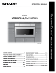
Microwave Drawer : SMD2470AS, SMD3070AS
Installation Manual
SPECIAL WARNING
INSTALLATION AND SERVICE MUST BE PERFORMED BY A QUALIFIED INSTALLER.
IMPORTANT: SAVE this installation manual FOR LOCAL ELECTRICAL INSPECTOR’S USE.
READ AND SAVE THESE INSTRUCTIONS FOR FUTURE REFERENCE.
Clearances and Dimensions
For SAFETY CONSIDERATIONS do not install drawer in any combustible cabinetry, which is not in accord with the stated
clearances and dimensions on pages 2 - 5. See Figure 1 (for 24") or Figures 4 and 5 (for 30").
Important notes to the Consumer
Unpacking your microwave drawer
• Remove all packing
materials from inside
the Microwave Drawer.
DO NOT REMOVE
THE WAVEGUIDE
COV E R, wh ich is
located on the top
of t he M ic r owave
Drawer.
Keep this manual with your Operation Manual for future
reference.
Sealing
surface
• As when using any microwave oven generating heat, there
are certain safety precautions you should follow. These are
listed in the Operation Manual. Read all and follow carefully.
Waveguide
cover
• Be sure your Microwave Drawer is installed and grounded
properly by a qualified installer or service technician.
Important Safety Instructions
Sealing
surface
• Remove the feature
sticker, if there is one.
Oven
Check the drawer for
cavity
any damage, such as
misaligned or bent
drawer, damaged drawer seals and sealing surfaces, broken
or loose Microwave Drawer guides and dents inside the cavity
or on the front side of the drawer. If there is any damage, do
not operate the Microwave Drawer and contact your dealer or
a SHARP AUTHORIZED SERVICER.
Mounting
flange
If the information in this manual is not followed
exactly, a fire or electrical shock may result that could cause
property damage, personal injury or death.
To reduce the risk of tipping, the Microwave
Drawer must be secured by a properly installed Anti-Tip
block.
• This Microwave Drawer must be electrically grounded in
accordance with local codes.
• Make sure the wall coverings and the cabinets around the
Microwave Drawer can withstand the heat generated by the
Microwave Drawer.
Important notes to the installer
• Read all of the Installation Manual before installing the
Microwave Drawer.
Never leave children alone or unattended in
the area where a Microwave Drawer is in use. Never leave the
drawer open when the microwave is unattended.
• Observe all governing codes and ordinances.
Stepping, leaning or sitting on the drawer may
result in serious injuries and can also cause damage to the
Microwave Drawer.
• Remove all packing material before connecting the electrical
supply.
• Be sure to leave these instructions with the consumer.
• Do not use the Microwave Drawer as a storage space.
This creates a potentially hazardous situation.
• Check that the time-of-day is in the display. If not, touch
STOP/CLEAR to prevent unintended use.
1
Clearances and Dimensions
• Your oven can be built into a cabinet or wall by itself or
under a gas or electric wall oven.
• Dimensions that are shown in Figure 1 (for 24") or Figures
4 and 5 (for 30") must be used. Given dimensions provide
minimum clearance. Locate electrical outlet in the shaded
area in the upper left-hand corner of the cutout. See Figure 9.
• Be sure that the clearance of the floor between the wall oven
and the microwave drawer is a minimum of 2-inches.
• Contact surface must be solid and level. Pay special attention
to the floor on which the Microwave Drawer will sit. The
floor of the opening should be constructed of plywood strong
enough to support the weight of the oven (about 100 pounds).
• The microwave interior will easily accommodate a 9" x 13"
oblong dish or a bag of microwave popcorn.
• The oven can also be mounted flush. Please see instructions
for flush mounting included with the Flush Mount Deflector
• Check location where the Microwave Drawer will be
installed for proper electrical supply.
vent.
24" Microwave Drawer Measurements
B
A
B
C
D
M
B
E
C
A
A
F
F
G
I
G
H
K
I
E
C
P
J
J
I
D
N
L
D
G
H
Figure 2
Figure 1
E
O
A.21-5/8"
B.4-11/16"
C.1-3/4"
D.21-7/8"
E.23-7/8"
Cutout Dimension 22 1/8" x 15 9/16"
A.6"
B. Suggested electrical outlet location*
C. Anti-Tip block
D.5"
E.3-1/2"
F.4"
G. 22-1/8" opening
H. 14-13/16" to bottom of Anti-Tip block
I. Allow 7/8" overlap
J. 23-1/2" minimum depth
K. Allow 3/16" overlap
L. 36" countertop height
M.Allow 7/16" minimum overlap
N. Floor must support 100 lb
O. 24" cabinet minimum
P. 15-9/16" opening
F
F.15-7/8"
G.14-19/32"
H.1-9/64" door thickness
I. 15" auto drawer opening
J.4"
Figures 1 and 2 contain many Microwave Drawer measurements
for reference when planning the drawer’s location.
This Microwave Drawer can be installed below any electric or
gas wall oven.
* Can also be installed using an electrical outlet in an adjacent cabinet
within the area where the provided electrical cord can reach. Power
cord access hole in cabinet should be a minimum 1 1/2" diameter
hole and deburred of all sharp edges.
IMPORTANT Always allow sufficient power cord length to the
electrical outlet to prevent tension.
Always check electrical codes for requirements.
2
This drawing represents a typical standard cabinet. If installed in custom
cabinets with extended counter tops, take into account visibility and access
to controls. See Figure 3.
A
Move oven location downward for
extended countertops
B
E
Extended countertops
Figure 3
C
D
G
F
3
A.25"
B.1/2"
C.15-7/8"
D.36"
E. Control panel shown in open position
F.24"
G.34-1/2"
30" Microwave Drawer Measurements
Figures 4, 5 and 6 contain many Microwave Drawer measurements
for reference when planning the drawer’s location.
* Can also be installed using an electrical outlet in an adjacent
cabinet within the area where the provided electrical cord can
reach. Power cord access hole in cabinet should be a minimum
1 1/2" diameter hole and deburred of all sharp edges.
This Microwave Drawer can be installed below any electric or
gas wall oven.
IMPORTANT
Always allow sufficient power cord length to the
electrical outlet to prevent tension.
Always check electrical codes for requirements.
A
B
Cutout Dimension 28 7/16" x 15 9/16"
E
D
C
F
G
I
H
J
A.84" wall cabinet
B.Optional wall oven cutout illustrated in sketch
C.Suggested electrical outlet location*
D.6"
E. Anti-Tip block
F.3-1/2"
G.5"
H.4"
I. 2" minimum
J. 28-7/16" opening
K.Allow 3/16" overlap
L. 14-13/16" to bottom of Anti-Tip block
M.Allow 3/4" overlap
N. 23-1/2" minimum depth
O.15-9/16" opening
P. Allow 7/16" overlap
Q.Floor must support 100 lb
R.30" cabinet minimum
K
L
O
M
N
M
Q
P
R
Figure 4
4
C
B
A
M
Cutout Dimension 28 7/16" x 15 9/16"
E
D
A.6"
B.Suggested electrical outlet location*
C.Anti-Tip block
D.5"
E.3-1/2"
F.4"
G.28-7/16" opening
H.14-13/16" to bottom of Anti-Tip block
I. Allow 3/4" overlap
J. 23-1/2" minimum depth
K.Allow 3/16" overlap
L. 36" countertop height
M.Allow 7/16" overlap
N.Floor must support 100 lb
O. 30" cabinet minimum
P. 15-9/16" opening
F
G
K
I
H
P
J
I
L
N
O
Figure 5
J
B
C
A
F
G
I
D
H
Figure 6
E
5
A.21-5/8"
B.4-11/16"
C.1-3/4"
D.21-7/8"
E.29-7/8"
F.15-7/8"
G.14-19/32"
H.1-9/64" door thickness
I. 15" auto drawer opening
J.4"
This drawing represents a typical standard cabinet. If installed in custom
cabinets with extended counter tops, take into account visibility and access
to controls. See Figure 7.
A
Move oven location downward for
extended countertops
B
E
Extended countertops
Figure 7
C
D
G
A.25"
B.1/2"
C.15-7/8"
D.36"
E. Control panel shown in open position
F.24"
G.34-1/2"
F
6
Anti-Tip BLOCK
NORMAL INSTALLATION STEPS
Anti-Tip BLOCK Installation Instructions
To reduce the risk of tipping of the drawer, the Anti-Tip block must be properly installed
located 14 13/16 -inches above the floor on which the Microwave Drawer will sit. The
6-inch Anti-Tip block must be provided by the installer. See Figures 1, 4 and 5. The
Anti-Tip block prevents serious injury that might result from spilled hot liquids.
If the Microwave Drawer is ever moved to a different location, the Anti-Tip block must
also be moved and installed. When installed to the wall, make sure that the screws
completely penetrate the dry wall and are secured in wood or metal so that the block
is totally stable. When fastening, be sure that the screws do not penetrate electrical
wiring or plumbing.
Figure 8
Electrical Outlet
The electrical requirements are a 120 volt 60 Hz, AC only, 15 amp. or more protected
electrical supply. It is recommended that a separate circuit serving only this appliance
be provided.
The drawer is equipped with a 3-prong grounding plug. It must be plugged into a wall
receptacle that is properly installed and grounded. Should you only have a 2-prong
outlet, have a qualified electrician install a correct wall receptacle.
Note: If you have any questions about the grounding or electrical instructions, consult
a qualified electrician or service person.
Figure 9
* Can also be installed using an electrical outlet in an adjacent cabinet within the area where
the provided electrical cord can reach.
Always check electrical codes for requirements.
Grounding Instructions
This appliance must be grounded. The Microwave Drawer is equipped with a cord
having a grounding wire with a grounding plug. It must be plugged into a wall receptacle
that is properly installed and grounded in accordance with the National Electrical Code
and local codes and ordinances. In the event of an electrical short circuit, grounding
reduces risk of electric shock by providing an escape wire for the electric current.
– Improper use of the grounding plug can result in a risk of electric
shock. Do not use an extension cord. If the power supply cord is too short, have a
qualified electrician or serviceman install an outlet near the appliance.
3-Prong plug
Grounded recepta
Grounding adapt
Grounding pin
Screw
3-Prong receptacle
Grounded receptacle box
7
Tab for grounding
Drawer Installation
1.Place the drawer adjacent to the wall or cabinet opening.
Plug the power supply cord into the electrical outlet.
2.Carefully guide the drawer into the prepared opening.
Avoid pinching the cord between the oven and the wall.
Parts supplied
3.Slide the drawer all the way until the mounting flange is
flush with the face of the cabinet. See Figure 10A.
4 Screws
4.Open the drawer. Using the 4 holes on the drawer as a
template, pre drill the cabinet using a 1/16" bit. See Figure
10A.
5.Secure the drawer with the 4 screws supplied. See Figure
10B.
Figure 10B
Mounting
flange
Figure 10A
Model and serial number location
The name plate includes model and serial number. Open the Microwave Drawer fully. The label is beyond the back wall of the microwave
cavity facing up from the flat surface.
Care, cleaning and maintenance
Refer to the Operation Manual for cleaning instructions.
Before you call for service
Read the BEFORE YOU CALL and operating instruction sections in your Operation Manual. It may save you time and expense. The
list includes common occurrences that are not the result of defective workmanship or materials in this range.
Refer to the warranty in your Operation Manual for Sharp’s toll-free service number and address. Please call or write if you have inquiries
about your microwave product and/or need to order parts.
SHARP ELECTRONICS CORPORATION
1 Sharp Plaza, Suite 1 • Mahwah, New Jersey 07495-1123
1-800-BE-SHARP (237-4277)
T IN S EB 5 3 9 MRR0
Feb 10, 2015
8