1
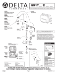
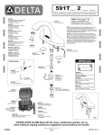
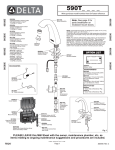
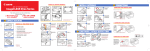
204499
204499
6__ __ T __ __0
204499
204499
Write purchase model number here for future reference
061099A
Arzo Spout Assembly
for Proximity
204499
204499
062000A
Grail Spout Assembly
for Proximity
RP54519
Aerator (1.5 GPM)
RP54519
Aerator
(1.5 GPM)
062005A
Spacer for
Grail Proximity
062001A
Proximity Thin Tab
204499
204499
062001A
Proximity Thin Tab
204499
204499
062004A
Spacer for Arzo Proximity
NOTE: For optimum performance of this product, we
recommend a system pressure between 20 and 80 PSI
static. This product will operate up to a maximum of
125 PSI static per ANSI and CSA requirements. However,
we do not recommend pressure above 80 PSI. Thermal
expansion or leaking pressure reducing valves may
require use of expansion tanks or relief valves to ensure
your system never exceeds its maximum intended
pressure setting.
060416A
Bypass
Adapter
060930A
Battery Box Assembly less driver
board and battery holder
060905A
Cover
Gasket
060906A
Surface
Mount
Housing
062002A
Proximity
Driver Board
060416A
Bypass Adaptor
060910A
Solenoid Valve
with 3/8”
Compression
Connectors
060908A
Solenoid Holder
OPTION LIST
060910A
Solenoid
Valve with
3/8”
Compression
Connectors
060684A
Square Battery Holder
060913A
3/8” x 3/8” Compression
Connector, Nut and Ferrule
060571A
Mounting Hardware
TRANSFORMERS
060704A
Transformer 110 to 24 VAC 20VA
up to 5 Electronic Valves
060771A
Transformer 110 to 24 VAC 40VA
up to 10 Electronic Valves
060772A
Transformer 110 to 24 VAC 100VA
up to 25 Electronic Valves
060909A
Screen Assembly
060683A
24 VAC to 6 VDC Converter
PLEASE LEAVE this M&I Sheet with the owner, maintenance plumber, etc. as
items relating to ongoing maintenance suggestions and procedures are included.
Page 1
204499 Rev. A
Installation should be in accordance with local plumbing and electrical codes.
FLUSH ALL PIPES THOROUGHLY BEFORE INSTALLATION.
INSTALLATION AND SET UP INSTRUCTIONS
STEP 1. FAUCET INSTALLATION
Mount faucet to sink using the provided components in the following order - washer,
thin capacitance tab, lock nut (Fig. 1). NOTE: Black rubber spacer must be used
at all times between the spout and countertop. The use of clear silicone
sealant between the rubber spacer and lavatory is not required.
Spout
Spout Hose
STEP 2. BATTERY BOX INSTALLATION
Rubber Spacer
Mount battery box to wall under sink using the 4 supplied screws and anchors. Use
1/4” drill for wall anchors. Be sure to install the box within the dimensions
provided so the hose and sensor cable will reach connections at faucet and
battery box. Refer to illustration (Fig. 2).
Washer
STEP 3. FLUSH SYSTEM
Thin Tab
Nut
To flush supply line, assemble these components as shown (Fig. 3) and run water
for one minute. Shut off water supply. Attach aerator. NOTE: Do not connect
supply to the solenoid inlet until line is flushed directly out spout.
Fig. 1
STEP 4. CONNECT WATER SUPPLY
Disassemble the components, reassemble the ones shown here (Fig. 4) supply line
and adapter to the bottom fitting on solenoid, polymer braided spout hose to the top
fitting on solenoid. Use Teflon® tape where indicated on adapter. Turn on water
supply. DO NOT SOLDER CONNECTIONS.
STEP 5. CONNECT PROXIMITY™ SENSOR
Run the white sensor wire along the polymer braided hose up to the underside of the
countertop (Fig. 2). Attach the female spade terminal to the thin capacitance tab
(Fig. 5). ENSURE A TIGHT CONNECTION IS MADE. Use tie wraps to bind the
white sensor wire along the polymer braided hose back to the control box (Fig. 2).
STEP 6. PREPARE SINK AREA
Before connecting the power - clean off counter and remove all objects from
the sink.
Fig. 2
STEP 7a. CONNECT POWER
IMPORTANT: ENSURE THAT WATER SUPPLY IS ON BEFORE PROCEEDING.
WHEN POWER IS FIRST APPLIED TO THE DRIVER BOARD, THE INSTALLER
MUST IMMEDIATELY STEP BACK AT LEAST 3 FEET FROM THE PROXIMITY
SPOUT IN ORDER TO ALLOW THE UNIT TO PROPERLY CALIBRATE.
BATTERY VERSION: Open the control box. Connect battery clip to battery pack.
Install four “C” batteries provided into the battery holder. An ascending beep tone
will be generated when power is first applied to the unit. At this stage, step back
at least 3 feet from the control box and spout in order to allow for proper
calibration. Do not secure the lid until after calibration.
HARDWIRE VERSION: Install CSA and/or UL approved Class 2 transformer or
equivalent in a convenient location or in a pipe chase. (Do NOT install the
transformer inside the control box.) With the power off, bring the 24 VAC supply
wires to the box. Connect the 24 VAC supply to the 060683A conversion kit (see
page 1). Connect the battery snap of the hardwire converter to the driver board
battery clip. Turn on power supply for the transformer. An ascending beep tone
will be generated when power is first applied to the unit. At this stage, step back
at least 3 feet from the control box and spout in order to allow for proper
calibration. Do not secure the lid until after calibration.
Spout
Hose
Bypass
Adapter
Ferrule
Nut
Teflon®
Tape
3/8" O.D.
Copper
Inlet
Fig. 3
Page 2
Fig. 4
204499 Rev. A
Installation should be in accordance with local plumbing and electrical codes.
FLUSH ALL PIPES THOROUGHLY BEFORE INSTALLATION.
INSTALLATION AND SET UP INSTRUCTIONS
STEP 7b. CALIBRATION
↓
After power is applied to the driver board, it generates an ascending beep tone
which prompts the installer to step away from the unit. During this process the
water will turn ON and OFF on its own as the unit undergoes calibration. Please
allow up to 30 seconds for the unit to calibrate itself to its new environment.
STEP 8. TEST FOR OPERATION
Test for operation. If OK, then close lid - Use caution not to damage wires or
components on electronic driver board. See Fig 6. Secure lid using screws.
If faucet leaks from spout outlet: SHUT OFF WATER SUPPLIES. Check proper
solenoid connection. Replace solenoid if problem persists. If faucet exhibits
very low flow: A) Remove and clean Spray Outlet or B) SHUT OFF WATER
SUPPLY. Clean or replace Screen Assembly (2). If unit does not work
properly, see Trouble Shooting Guide on page 5.
STEP 9. BASIC OPERATION AFTER CALIBRATION
Proximity™ sensing technology works by creating an electrical field around
a conductor (the spout) and monitoring the change in capacitance that
the conductor undergoes. The change in capacitance (the ability to store
an electrical charge) is brought on by a 2nd conductor (a human body)
entering the Proximity™ field. As the human hand enters and leaves the
vicinity of the electrical field around the spout, the solenoid is opened and
closed accordingly. It is critical in the installation process that all electrical
and mechanical connections be as tight and rigid as possible, ensuring a
smooth signal is carried from the driver board to the spout, and back again.
Fig. 5
NOTE: Always make
sure driver board is in
place before inserting
the battery pack. Use
caution not to pinch
wires or damage
components on the
electronic driver board.
Trap
jacket of
cable in
hole for
strain
relief.
Fig. 6
1
2
Upon calibration, test the function of the product by
placing your hands within close proximity of the
spout. The solenoid will open, then close once
hands are removed from the sensing zone.
Page 3
204499 Rev. A
Installation should be in accordance with local plumbing and electrical codes.
FLUSH ALL PIPES THOROUGHLY BEFORE INSTALLATION.
INSTALLATION AND SET UP INSTRUCTIONS
STEP 10. MAKING ADJUSTMENTS
Since some sink types (i.e. stainless steel) are made of a conductive material, and some installations may be near other foreign
conductive materials, adjustments to the sensitivity of the electrical field may be required to ensure a consistent operation. If
you find that after ensuring all electrical and mechanical connections are firm and rigid that the product is still not performing
consistently, the default sensitivity settings of the driver board may be adjusted. Follow these steps to make sensitivity adjustments.
1. Turn off the power to the driver board by disconnecting the driver board from the battery pack or hardwire converter.
NOTE: When disconnecting power - grab the battery connection and wait at least one second before disconnecting the
power. When the battery connection is touched, it trips the electronics and turns on the solenoid. Waiting for at least one
second before disconnecting the power will allow the electronics to reset themselves and shut off the solenoid.
2. Locate the sensitivity selector switch located on the driver board (Fig. 7).
3. Using a finger or small screwdriver, gently set the sensitivity level one step down from its current position. Use the sensitivity
selection chart (Fig. 7) to ensure the correct setting is chosen.
4. Once the selection has been made, re-apply power to the driver board and allow for calibration as per Step 7a and 7b.
5. Test for operation and repeat steps 1-4, if necessary.
Sensitivity Levels:
As a rule of thumb, the High sensitivity
level will produce a sensing range of
approximately 4.0”. The Low sensitivity
level will reduce the electrical field so
much so that the spout must be touched
in order to operate.
Switch 1
ON
ON
OFF
OFF
Switch 2 Sensitivity
ON
OFF
ON
OFF
HIGH
MEDIUM HIGH
MEDIUM LOW
LOW
NOTE: Fig. 7 depicts a driver board with
the LOW Sensitivity setting selected.
Fig. 7
Page 4
204499 Rev. A
CARE INSTRUCTIONS
This Delta Commercial faucet is designed and engineered in accordance with the highest quality and performance standards. With
proper care, it will give you years of trouble free service. Care should be given to the cleaning of this product. Although the chrome
finish is extremely durable, it can be DAMAGED by ACIDIC CLEANERS (i.e., cleaners designed specifically for vitreous china
lavatories and water closets), HARSH ABRASIVES or POLISH. To clean, simply wipe the surface with a damp cloth and blot dry with
a soft towel.
TROUBLE SHOOTING GUIDE
If the faucet does not work properly, follow the steps below in order.
Check to ensure faucet was installed
according to the M&I sheet.
Note: See instructions on pages 1 to 4.
Test for operation. If unit does not
operate:
Check to be sure that white sensor wire is firmly connected to the thin
capacitance tab, and that the nut and washer are firmly connected to
the underside of the counter top. See Fig. 1 on page 2.
Check to be sure power cable is properly secured in fitting.
Check to be sure batteries are fresh and properly installed.
Check two wires to solenoid to be sure they are connected correctly.
Check to be sure water supply is turned on.
If faucet shuts off due to interference:
When the faucet detects an object for longer than 45 seconds, or if
faucet self-cycles for 4 times within 15 seconds, it will automatically shut
off. This will be followed by 3 quick beeps which indicate that calibration
is about to take place. The faucet will then enter calibration per step 7b.
Once calibration takes place (with no user present) the faucet will return
to regular operation.
Faucet makes a beeping noise.
(Different from re-calibration in step 1):
BATTERY POWERED: Faucet beeps twice when turning off:
indicates batteries are low and need to be replaced (1500 cycles or 2
weeks left). Faucet beeps continuously when hands in front of
spout and no water: faucet locked out because batteries are too low.
Replace batteries.
HARDWIRE: Check voltage from converter and transformer. It should
be approximately 6.4 volts DC coming from converter to the driver
board.
Replace Hardwire
converter 060683A, if
required.
Continuous beeping tone upon power-up:
BATTERY POWERED: Check to ensure all batteries are inserted
correctly.
HARDWIRE: Check voltage from converter to transformer.
Ensure battery polarities
are correct and that
voltage is sufficient around 6 volts.
The faucet stops working. No water flow.
Check the function of the solenoid.
The solenoid should “click” when activated.
Step 1
Step 2
If there is a
clicking sound:
Step 3
If no clicking
sound:
If faucet does not activate or works
erractically:
This indicates that both the sensor and the solenoid are functioning.
Ensure inlet screen on solenoid is not plugged with debris.
Clean as required.
Check the incoming water supply. Turned on, proper pressure and
volume, etc.
Correct as required.
Check for a pressure lock between the mixing valve and the solenoid.
Turn off the water supply and undo the connection to the inlet of the
solenoid, this will eliminate any built-up pressure.
Then activate sensor and test fire the solenoid.
If after above there is no clicking sound;
Defective solenoid.
Replace 060910A
Solenoid.
Check for electrical interference.
Call Technical Service if
any such conditions
found. 1-800-387-8277.
Check for interference from other electrical devices within close
proximity to the spout or battery box. Devices such as other infrared
devices, transformers, etc.
Excessive water on the counter top may lead to an overly sensitive
faucet. Wipe water off, re-calibrate the faucet.
Step 4
Re-calibrate the unit by disconnecting the batteries for 10 seconds, then
reconnecting. Follow steps 7a and 7b of the Installation and Set-Up
Instructions.
Water runs non stop when batteries are
disconnected:
Step 5
Replace batteries.
BATTERY and HARDWIRE POWERED: When battery connection is
touched, it trips the electronics and turns on the solenoid.
When disconnecting the
power, grab the battery
clip and wait for at least
one full second before
disconnecting it.
Solenoid will shut off
after power disconnected.
If after completion of all above steps, the valve still does not function correctly; Call Technical Service for further assistance at 1-800-387-8277.
Page 5
204499 Rev. A
Delta Commercial Faucet Limited Warranty
All parts of the Delta® HDF® and TECK® faucets are warranted to the original consumer purchaser to be free from defects in material, finish and workmanship for a period of
five (5) years unless otherwise specifically stated in the catalogue and price book. This warranty is made to the original consumer purchaser and shall be effective from date
of purchase as shown on purchaser’s receipt.
Delta will, at its option, repair or replace, FREE OF CHARGE, during the warranty period, any part which proves defective in material or workmanship under normal installation,
use and water and service conditions. If Delta Faucet concludes that the returned part was manufactured by Delta Faucet and is, in fact, defective, then Delta Faucet will
honour the warranty stated herein. Replacement parts can be obtained from your local dealer or distributor listed in the telephone directory or by returning the part along
with the purchaser’s receipt to our factory, TRANSPORTATION CHARGES PREPAID, at the address listed. THIS WARRANTY IS THE ONLY EXPRESS WARRANTY MADE BY DELTA.
ANY CLAIMS MADE UNDER THIS WARRANTY MUST BE MADE DURING THE FIVE YEAR PERIOD REFERRED TO ABOVE. ANY IMPLIED WARRANTIES, INCLUDING THE IMPLIED
WARRANTY OF MERCHANTABILITY OF FITNESS FOR A PARTICULAR PURPOSE, ARE LIMITED IN DURATION TO THE DURATION OF THIS WARRANTY. LABOUR CHARGES AND/OR
DAMAGE INCURRED IN INSTALLATION, REPAIR OR REPLACEMENT AS WELL AS INCIDENTAL AND CONSEQUENTIAL, SPECIAL, INDIRECT OR PUNITIVE DAMAGES CONNECTED
THEREWITH ARE EXCLUDED AND WILL NOT BE PAID BY DELTA FAUCET.
Some states do not allow limitations on how long an implied warranty lasts, or the exclusion or limitation of incidental or consequential damages, so the above limitations or
exclusions may not apply to you. This warranty gives you specific legal rights, and you may also have other rights which vary from state to state.
This warranty is for commercial products only from Delta Faucet Company and Delta Faucet Canada (a division of Masco Canada Limited) and is void for any damage to this
faucet due to misuse, abuse, neglect, accident, improper installation, any use in violation of instructions furnished by Delta Faucet or any use of replacement parts other than
genuine Delta parts.
Garantía Limitada de las Llaves de Agua Comerciales Delta
Todas las piezas de las llaves de agua (grifos) Delta® HDF®, TECK® están garantizadas al comprador consumidor original de estar libres de defectos de material, acabado y
fabricación por un periodo de cinco (5) años a menos que sea establecido específicamente de otra manera en el catálogo o libro de precios. Esta garantia se le hace al
comprador consumidor original y será efectiva desde la fecha de compra como mostrado en el recibo del comprador.
Delta, a su opción, reparará o reemplazará, GRATUITAMENTE, durante el periodo de garantía, cualquier pieza que pruebe ser defectuosa en material o fabricación bajo
instalación, usu, agua y condiciones de servicio normales. Si Delta Faucet concluye que la pieza devuelta fue fabricada por Delta Faucet y es, de hecho, defectuosa, entonces
Delta Faucet honrará la garantía establecida en este documento.
Las piezas de repuesto se pueden obtener de su comerciante o distribuidor local listado en el libreto telefónico o devolviendo la pieza junto con el recibo del comprador a
nuestra fábrica, CARGOS DE TRANSPORTE PRE-PAGADOS, a la dirección incluida. ESTA GARANTÍA ES LA ÚNICA GARANTÍA EXPRESA HECHA POR DELTA. CUALQUIER
RECLAMO HECHO BAJO ESTA GARANTÍA DEBE SER HECHO DURANTE EL PERÍODO DE CINCO AÑOS ARRIBA MENCIONADO. CUALQUIER GARANTÍA IMPLÍCITA, INCLUYENDO
LA GARANTÍA IMPLÍCITA DE COMERCIABILIDAD DE EMPLEO PARA UN PROPÓSITO PARTICULAR, TIENE UNA DURACIÓN LIMITADA A LA DURACIÓN DE ESTA GARANTÍA. LOS
CARGOS DE LABOR Y/O DAÑO INCURRIDO DURANTE LA INSTALACIÓN, REPARACIÓN O REPUESTO COMO TAMBIÉN DAÑOS INCIDENTALES O RESULTANTES, ESPECIALES,
INDIRECTOS O PUNITIVOS RELACIONADOS CON LO MENCIONADO SON EXCLUIDOS Y NO SERÁN PAGADOS POR DELTA FAUCET.
Algunos estados no permiten limitaciones de la duración de una garantía implícita limitada, o la exclusión o limitación de daños incidentales o consecuentes, de manera que
las limitaciones o exclusiones arriba mencionadas puedan no aplicarle a usted. Esta garantía le da derechos legales especificos, y usted también puede tener otros derechos
que varían de estado a estado.
Esta garantía es solo para productos comerciales de Delta Faucet Company y Delta Faucet Canada, una división de Masco Canada Limitada, y es nula por cualquier daño
hecho a esta llave de agua resultante del mal uso, abuso, descuido, accidente, instalación incorrecta, cualquier uso en violación de las instrucciones proporcionadas por Delta
Faucet o cualquier uso de piezas de repuesto que no sean de piezas genuinas de Delta.
Garantie Limitée Delta Commercial
Toutes les pièces des robinets de marque Delta® HDF® et TECK® sont garanties contre tout défaut de matière, de finition et de main-d’oeuvre pour une période de cinq (5)
ans, sauf indication contraire stipulée dans le catalogue et la liste des prix. Cette garantie est offerte à l’acheteur original et entre en vigueur à compter de la date d’achat
indiquée sur la preuve d’achat.
Delta procédera, à son entière discrétion, à la réparation ou au remplacement, SANS FRAIS, durant la période de garantie, de toute pièce qui présente un défaut de matière ou
de main-d’oeuvre dans des conditions d’installation, d’usure, d’eau et de service normales. Si Delta Faucet détermine que la pièce retournée a été fabriquée par Delta Faucet
et qu’en effect, cette pièce fait défaut, Delta Faucet respectera alors la garantie stipulée aux présentes. Les pièces de rechange peuvent être obtenues chez votre marchand
local ou le distributeur inscrit dans votre annuaire téléphonique, ou en retournant la pièce ainsi que la preuve d’achat à notre usine, FRAIS DE TRANSPORT PRÉPAYÉS, à
l’adresse indiquée. CETTE GARANTIE EST LA SEULE GARANTIE EXPRESSE FAITE PAR DELTA.
TOUTE RÉCLAMATION FAITE EN VERTU DE CETTE GARANTIE DOIT ÊTRE PRÉSENTÉE DURANT LA PÉRIODE DE CINQ ANS MENTIONÉE CI-DESSUS. TOUTE GARANTIE IMPLICITE,
Y COMPRIS LA GARANTIE IMPLICITE DE VALEUR COMMERCIALE RELATIVEMENT À L’APTITUDE À LA FONCTION, EST LIMITÉE EN TERMES DE DURÉE POUR LA DURÉE DE CETTE
GARANTIE.
LES FRAIS DE MAIN-D’OEUVRE ET/OU DE DOMMAGES ENCOURUS DURANT L’INSTALLATION, LA RÉPARATION OU LE REMPLACEMENT AINSI QUE LES DOMMAGES-INTÉRÉTS
ACCESSOIRES OU IMMATÉRIELS, SPÉCIAUX, INDIRECTS OU PUNITIFS S’Y RAPPORTANT SONT EXCLUS ET NE SERONT PAS PAYÉS PAR DELTA FAUCET.
Certains états ne permettent pas la limitation de la durée de la garantie implicite, ou l’exclusion ou la limitation des dommages-intérêts accessoires ou immatériels, et par
conséquent, les limitations ou les exclusions stipulées ci-dessus peuvent ne pas s’appliquer dans votre cas. Cette garantie vous accorde certains droits reconnus par la loi et
vous avez peut-être aussi d’autres droits qui varient d’un état à l’autre.
Cette garantie s’applique seulement aux produits commerciaux des sociétés Delta Faucet et Delta Faucet Canada, une filiale de Masco Canada Limited et est nulle de plein
droit pour tout dommage causé à ce robinet en raison d’usage excessif, d’abus, de négligence, d’accident, de mauvaise installation, tout usage en contravention des
directives fournies par Delta Faucet ou tout usage de pièces de rechange autres que des pièces originales Delta.
Delta Faucet Canada, a division of Masco Canada Limited
Box 5750, 420 Burbrook Place, London, ON, Canada N6A 4L6
1-800-567-3300 (English) 1-800-265-9245 (French)
Delta Faucet Company
Box 40980, 55 East 111th St., Indianapolis, IN, U.S.A. 46280
(317) 848-1812
For further technical assistance, call Delta Commercial Technical Service at 1-800-387-8277.
Para la asistencia técnica adicional, servicio técnico Comercial del Delta de la llamada en 1-800-387-8277.
Pour obtenir de l’assistance technique, appelez le Service Technique de Delta Commercial au 1-800-387-8277.
www.deltafaucet.com
Page 6
204499 Rev. A