1
Installation should be in accordance with local plumbing and electrical codes.
FLUSH ALL PIPES THOROUGHLY BEFORE INSTALLATION.
INSTALLATION AND SET UP INSTRUCTIONS
STEP 1. FAUCET INSTALLATION
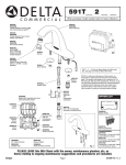
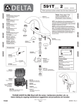
Mount faucet to sink using the provided components in the following order - washer,
thin capacitance tab, lock nut (Fig. 1). NOTE: Black rubber spacer must be used
at all times between the spout and countertop. The use of clear silicone
sealant between the rubber spacer and lavatory is not required.
Spout
Spout Hose
STEP 2. BATTERY BOX INSTALLATION
Rubber Spacer
Mount battery box to wall under sink using the 4 supplied screws and anchors. Use
1/4” drill for wall anchors. Be sure to install the box within the dimensions
provided so the hose and sensor cable will reach connections at faucet and
battery box. Refer to illustration (Fig. 2).
Washer
STEP 3. FLUSH SYSTEM
Thin Tab
Nut
To flush supply line, assemble these components as shown (Fig. 3) and run water
for one minute. Shut off water supply. Attach aerator. NOTE: Do not connect
supply to the solenoid inlet until line is flushed directly out spout.
Fig. 1
STEP 4. CONNECT WATER SUPPLY
Disassemble the components, reassemble the ones shown here (Fig. 4) supply line
and adapter to the bottom fitting on solenoid, polymer braided spout hose to the top
fitting on solenoid. Use Teflon® tape where indicated on adapter. Turn on water
supply. DO NOT SOLDER CONNECTIONS.
STEP 5. CONNECT PROXIMITY™ SENSOR
Run the white sensor wire along the polymer braided hose up to the underside of the
countertop (Fig. 2). Attach the female spade terminal to the thin capacitance tab
(Fig. 5). ENSURE A TIGHT CONNECTION IS MADE. Use tie wraps to bind the
white sensor wire along the polymer braided hose back to the control box (Fig. 2).
STEP 6. PREPARE SINK AREA
Before connecting the power - clean off counter and remove all objects from
the sink.
Fig. 2
STEP 7a. CONNECT POWER
IMPORTANT: ENSURE THAT WATER SUPPLY IS ON BEFORE PROCEEDING.
WHEN POWER IS FIRST APPLIED TO THE DRIVER BOARD, THE INSTALLER
MUST IMMEDIATELY STEP BACK AT LEAST 3 FEET FROM THE PROXIMITY
SPOUT IN ORDER TO ALLOW THE UNIT TO PROPERLY CALIBRATE.
BATTERY VERSION: Open the control box. Connect battery clip to battery pack.
Install four “C” batteries provided into the battery holder. An ascending beep tone
will be generated when power is first applied to the unit. At this stage, step back
at least 3 feet from the control box and spout in order to allow for proper
calibration. Do not secure the lid until after calibration.
HARDWIRE VERSION: Install CSA and/or UL approved Class 2 transformer or
equivalent in a convenient location or in a pipe chase. (Do NOT install the
transformer inside the control box.) With the power off, bring the 24 VAC supply
wires to the box. Connect the 24 VAC supply to the 060683A conversion kit (see
page 1). Connect the battery snap of the hardwire converter to the driver board
battery clip. Turn on power supply for the transformer. An ascending beep tone
will be generated when power is first applied to the unit. At this stage, step back
at least 3 feet from the control box and spout in order to allow for proper
calibration. Do not secure the lid until after calibration.
Spout
Hose
Bypass
Adapter
Ferrule
Nut
Teflon®
Tape
3/8" O.D.
Copper
Inlet
Fig. 3
Page 2
Fig. 4
204499 Rev. A