Transcript
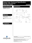
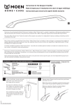
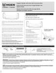
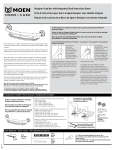
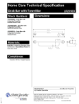
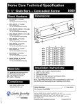
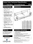
Home Care Technical Specification Designer Elegance Grab Bar w/ Grip Pads Dimensions: Stock Numbers: LR8716D1GBN – 16” Designer Elegance Grab Bar w / Grip Pads Brushed Nickel Finish, 1 ¼” Bar, Concealed Screw Mounting LR8724D1GBN – 24” Designer Elegance Grab Bar w / Grip Pads Brushed Nickel Finish, 1 ¼” Bar, Concealed Screw Mounting LR8716D1GCH – 16” Designer Elegance Grab Bar w / Grip Pads Chrome Finish, 1 ¼” Bar, Concealed Screw Mounting LR8724D1GCH – 24” Designer Elegance Grab Bar w / Grip Pads Chrome Finish, 1 ¼” Bar, Concealed Screw Mounting LR8716D1GOWB – 16” Designer Elegance Grab Bar w / Grip Pads Old World Bronze Finish, 1 ¼” Bar, Concealed Screw Mounting LR8724D1GOWB – 24” Designer Elegance Grab Bar w / Grip Pads Old World Bronze Finish, 1 ¼” Bar, Concealed Screw Mounting Materials: 1 ¼” Grab Bar rods are formed from (.040) type 304 stainless steel tubing. LR8700D1G A B C D E 16" Grab Bar 16.00 19.15 3.15 2.80 1.50 24" Grab Bar 24.00 27.15 3.15 2.80 1.50 Installation Instructions: 1. 2. Ple ase note that scre ws MUST be mounted into a wood stud for secure installation. Slide the decorative cover away from the hub end to e xpose the SecureMount™ m ounting flange. Do not remove protective plastic from decorative cover until indicated later in these instructions. 3. Locate the studs behind the wall by using a stud sensor or other stud locating m e thod. Studs are usually 16 in. apart; locate the center of each stud. 4. Moving aside the decorative cover as needed, with a pencil, mark three of the m ounting locations on e ach of the two grab bar flanges. Two m arks to be made above the grab bar in the area indicated in the illustration below. The third m ark to be m ade below the grab bar in the area indicated in the illustration below. De cide whe ther you would like to position your grab bar horizontally, ve rtically or at an angle, re membering that BOTH ends of the grab bar MUST be positioned ove r a wood stud. 5. Moving the decorative cover as far away from the marked slots as possible, drill a hole into the m arks, through the slots (as shown in illustration). Position the drill at a slight angle in order to get around the grab bar and decorative cover, making sure to drill into the wood stud. If desired, apply silicone caulk to the back of th e de corative cover to guard against wate r penetration. 6. To m ount the grab bar, re position one end of the grab bar SecureMount™ m ounting flange over the m arked holes. 7. Thre ad a washer onto each screw. Using the screwdriver, screw the wood scre ws with washe rs into the Se cureMount™ mounting flange at one end of the grab bar. The n screw the wood screws with washers into the mounting flange at the other e nd of the grab bar. 8. Tighten the scre ws until secure. 9. Slide the decorative cover over the Se cure Mount™ m ounting flange, rotating to find the corre ct fit before snapping into place. 10. Slide decorative covers over Se cureMount™ mounting flanges. Stock Number:_________________________Grab Bars By Creative Specialties 2 5 3 0 0 A L MO E N D R I V E N O R TH O L MS TE D , O H 4 4 0 7 0 C O R P O R A TE H E A D Q U A R TE R S : ( 8 0 0 ) 3 2 1 - 8 8 0 9 F A X: ( 8 0 0 ) 8 4 8 - 6 6 3 6 I N TE R N A TI O N A L : ( 4 4 0 ) 9 6 2 - 2 0 0 0 F A X: ( 4 4 0 ) 9 6 2 - 2 7 2 6 C U S TO ME R S E R V I C E ( U S A ) : 8 0 0 - 8 8 2 - 0 1 1 6 F A X: ( 8 8 8 ) 3 7 9 - 2 7 2 0 W W W . MO E N . C O M Copyright Creative Specialties International 2005 Literature #BA1669