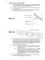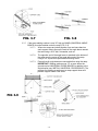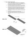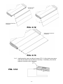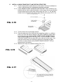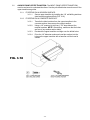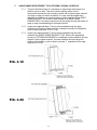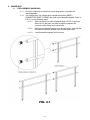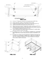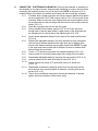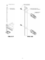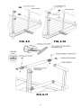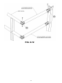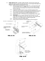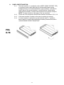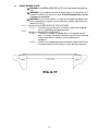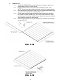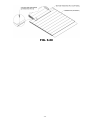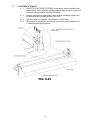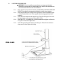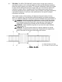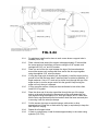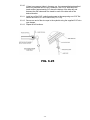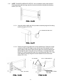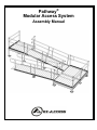
1
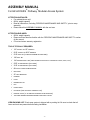
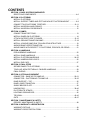
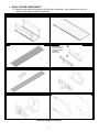
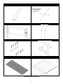
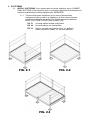
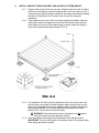
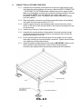
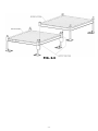
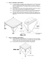
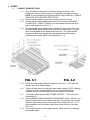
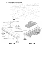
Pathway® Modular Access System Assembly Manual ASSEMBLY MANUAL For EZ-ACCESS® Pathway® Modular Access System ATTENTION INSTALLER: For residential use only! 850 lb. weight capacity Read all instructions, including ‘PERIODIC MAINTENANCE AND SAFETY,' prior to ramp assembly Please leave this ASSEMBLY MANUAL with the end user ATTENTION END USER: 850 lb. weight capacity Please read and become familiar with the ‘PERIODIC MAINTENANCE AND SAFETY’ section of this manual Fill out and return warranty registration TOOLS TYPICALLY REQUIRED: 1/2″ SOCKET OR 1/2″ WRENCH 9/16″ SOCKET OR 9/16″ WRENCH 5/16″ DRILL BIT (IF BRACE ASSEMBLIES ARE USED) 1/8″ DRILL BIT 1/4″ MASONRY DRILL BIT (USED WHEN INSTALLING TO CONCRETE PORCH, STEP, ETC.) 5/32″ ALLEN WRENCH (INCLUDED) 3/16″ ALLEN WRENCH (INCLUDED) #2 PHILLIPS HEAD SCREW DRIVER BOX KNIFE 25’ TAPE MEASURE HAMMER LEVEL RUBBER MALLET FILE POWER DRILL HACKSAW (FOR OPTIONAL HANDRAIL KITS) DIGGING TOOLS (IF AN OBSTACLE NEEDS TO BE REMOVED) TWO ABLE-BODIED PERSONS NEEDED FOR INSTALLATION VIEW PACKING LIST: Each ramp system is shipped with a packing list. Be sure to check that all items and tools are present before starting installation. -2- CONTENTS SECTION 1: BASIC SYSTEM COMPONENTS IDENTIFYING COMPONENTS ....................................................................................... 4-6 SECTION 2: PLATFORMS INSTALL PLATFORMS ...................................................................................................... 7 INSTALL SUPPORT TUBES AND FEET AND ADJUST PLATFORM HEIGHT .............. 8-9 CONNECT TWO PLATFORMS TOGETHER .............................................................. 10-11 INSTALL UNIVERSAL ANGLE BRACE ........................................................................... 12 INSTALL UNIVERSAL CROSS BRACE........................................................................... 12 SECTION 3: RAMPS CONNECT RAMP SECTIONS ......................................................................................... 13 INSTALL RAMPS ON PLATFORMS ................................................................................ 14 ATTACH SUPPORT LEGS TO RAMPS ...................................................................... 15-16 INSTALL GROUND TRANSITION RAMP ................................................................... 17-18 INSTALL A SINGLE RAMP RUN TO AN EXISTING STRUCTURE ................................. 19 ANCHOR RAMP UPPER TRANSITION........................................................................... 20 ANGLE RAMPS WITH RESPECT TO PLATFORMS, PORCHES, OR DECKS ............... 21 SECTION 4: HANDRAILS PRE-ASSEMBLE HANDRAILS ........................................................................................ 22 INSTALL RAMP HANDRAILS .......................................................................................... 23 INSTALL PLATFORM HANDRAILS ............................................................................ 24-25 INSTALL HANDRAIL END LOOPS .................................................................................. 26 INSTALL END CAPS ....................................................................................................... 27 SECTION 5: FINAL STEPS SECURE RAMPS TO PLATFORMS ................................................................................ 28 TOUCH-UP ARCHITECTURALLY FINISHED HANDRAILS ............................................ 28 FINAL CHECKS ............................................................................................................... 28 SECTION 6: OPTIONAL EQUIPMENT CONNECTOR – RAMP HR TO RAMP HR.................................................................. 29-31 CONNECTOR – PLATFORM HR TO RAMP HR ........................................................ 32-35 RAMP SUPPORT – TOP ................................................................................................. 36 RAMP LOWER TRANSITION .......................................................................................... 37 SINGLE BRIDGE PLATE ................................................................................................. 38 LANDING PAD............................................................................................................ 39-40 PLATFORM TIE STRAPS ................................................................................................ 41 LIGHTNING GROUND ROD ............................................................................................ 42 TIE DOWN .................................................................................................................. 43-45 GATE .......................................................................................................................... 46-47 SECTION 7: MAINTENANCE & SAFETY PERIODIC MAINTENANCE & SAFETY ........................................................................... 48 SECTION 8: WARRANTY & REGISTRATION WARRANTY DETAILS ..................................................................................................... 49 WARRANTY REGISTRATION FORM.............................................................................. 49 -3- 1. BASIC SYSTEM COMPONENTS 1.1. Because each ramp configuration will differ from one another, your system may or may not contain all these basic system components. MODULAR RAMP WITH HANDRAIL MODULAR RAMP WITHOUT HANDRAILS MRLT – RAMP LOWER TRANSITION MRRC – CONNECTOR – RAMP TO RAMP NOTE: INCLUDES COMPONENTS TO CONNECT RAMPS AND RAMP HANDRAILS. MRUT – RAMP UPPER TRANSITION MRST - RAMP SUPPORT TOP MRHBPR - RAMP HANDRAIL END BRACKET (PAIR) MRHRLNS & MRHRL- HANDRAIL END LOOPS ITEMS NOT SHOWN ACTUAL SIZE -4- UNIVERSAL PLATFORM (STRAIGHT CONFIGURATION) UNIVERSAL PLATFORM (TURN CONFIGURATION) MPPC – CONNECTOR – PLATFORM TO PLATFORM MHRRRC – CONNECTOR – RAMP HR TO RAMP HR MHRPRC – CONNECTOR – PLATFORM HR TO RAMP HR MBP36, MBP48, MBP60 - BRIDGE PLATE MSTSXXPR - FEET & SUPPORT TUBE PAIRS MHREC - HANDRAIL END CAP XX DENOTES USABLE LENGTH (LENGTHS AVAILABLE 10” THROUGH 100") ITEMS NOT SHOWN ACTUAL SIZE -5- MUAB – UNIVERSAL ANGLE BRACE MUCB5 & MUCB7 – UNIVERSAL CROSS BRACE NOTE: MUCB5 USED UP TO 5’ PLATFORM SIDE & MUCB7 USED OVER 5’ PLATFORM SIDE MUG36 – MODULAR GATE 36” MTDK – TIE DOWN KIT MPTS – PLATFORM TIE STRAP MRHP - RAMP HANGER PAIR MRGT – RAMP GROUND TRANSITION MLP – LANDING PAD ITEMS NOT SHOWN ACTUAL SIZE -6- 2. PLATFORMS 2.1. INSTALL PLATFORMS: If your system does not include a platform, skip to ‘CONNECT RAMP SECTIONS’ of this instruction guide. It is strongly suggested that all platforms and ramps be installed before installing handrails (see ‘HANDRAILS’). 2.1.1. There are three types of platforms (one or more of these platform arrangements may be used in an installation). All three require the same procedure for assembly except for FIG.2.3 which requires an additional MPPC (PLATFORM TO PLATFORM CONNECTOR). FIG. 2.1 Universal platform straight configuration FIG. 2.2 Universal platform turn configuration FIG. 2.3 Platform turn back configuration (two 5' x 4' platforms shown combined to make 5' x 8’ turn back platform). FIG. 2.1 FIG. 2.2 FIG. 2.3 -7- 2.2. INSTALL SUPPORT TUBES AND FEET AND ADJUST PLATFORM HEIGHT: 2.2.1. Support tubes, plugs & feet come in pairs. Support tubes will come in lengths sufficient for the heights at specific locations and should not need to be cut. It is recommended that the plug be installed in the support tube before installing the tube into the platform, but it can be done at any point during the installation. 2.2.2. Tip the platform on its side. Have one person support the platform while the other person slides the support tubes into the four platform corner pockets. Insert plugs into the top of the support tubes as shown. Adjust the support tubes to the approximate height needed (FIG.2.4). FIG. 2.4 2.2.3. Use supplied 3/16″ Allen wrench to tighten one of the two set screws in the corner pocket, just enough to hold the support tube in place but do not over tighten (the second set screw will be tightened after final height adjustments are complete). NOTE: The universal platform configured as a turn back platform (FIG. 2.3) will have six tubes to adjust. WARNING: Do not attempt to walk on the platform until all support tube set screws have been tightened securely. 2.2.4. Place the platform with support tubes attached into the upright position. IMPORTANT: Do not let the weight of the platform bear on the support tubes while tipping the platform upright. -8- 2.2.5. Lift each corner of the platform and install a base foot on each support tube oriented so that the foot extends under the platform as shown in FIG. 2.4. Make sure the feet are fully engaged on the tubes and tighten the thumb screw on each foot securely. NOTE: If installing on soft soil it may be necessary to set the base foot on a concrete pad. 2.2.6. Adjust the final height of the platform. 2.2.7. Adjust legs one at a time by loosening the set screws in the platform corner pockets. Using a level, adjust the platform height and re-tighten. 2.2.8. Once the final height has been adjusted, tighten the second set screw in each platform corner pocket. 2.2.9. Ensure that all set screws are secure and install plugs in the top of each support tube if not done previously. -9- 2.3. CONNECT TWO PLATFORMS TOGETHER: 2.3.1. Assemble the first platform as described in the previous steps except on the side where the second platform will connect, install two MPPC (CONNECTOR – PLATFORM TO PLATFORM) before installing feet onto the support tubes. Make sure the platform connector set screws are oriented outward so they will be accessible. NOTE: Any two platforms of the same width can be connected. However, two 5' x 4’ platforms are usually connected to make a turn back platform. 2.3.2. Slide the platform connectors up until they contact the bottom of the platform and tighten the set screws securely (FIG. 2.5). 2.3.3. Install a support tube stub into the open pocket in each connector until the bottom of the stub is flush with the bottom of the connector and tighten the set screws securely. 2.3.4. Install a plug in the top of each support tube stub. 2.3.5. Assemble the second platform as described in the previous section except only install support tubes, plugs and feet on the opposite side of where the platforms will connect (FIG. 2.6). 2.3.6. Lift the second platform and slide the open corner pockets over the support tube stubs extending up from the platform connectors. Tighten the set screws in the platform corner pockets securely. 2.3.7. Adjust the platform heights and level as needed. IMPORTANT: Make sure all the set screws in both the platform corner pockets and the platform connectors are tightened securely before proceeding with the installation. FIG. 2.5 - 10 - FIG. 2.6 - 11 - 2.4. INSTALL UNIVERSAL ANGLE BRACE: 2.4.1. For added stability, any platform with a walking surface over 36″ high requires bracing. The MUAB (UNIVERSAL ANGLE BRACE) is used for surfaces 36″ up to 72″. Walking surfaces 72″ and higher require cross braces in addition to the angle braces. 2.4.2. Angle braces come in pairs. Use four pairs per platform (one pair per support tube, or side) or six pairs when two platforms are connected. 2.4.3. Use two brace bands to secure the ends of the two angle braces nearest the twist to the support tube using a 5/16" bolt, flat washer, and nut (FIG. 2.7). 2.4.4. Opposite ends of the braces are attached to the bottom of the platform side rail at 90° to each other using a 1/4″ square drive pan head self-drilling screw (FIG. 2.7). FIG. 2.7 2.5. INSTALL UNIVERSAL CROSS BRACE: 2.5.1. Install UNIVERSAL CROSS BRACES on all support tubes when the walking surface is 72″ or more above the ground. Cross braces are normally installed on all four sides (FIG. 2.8) unless two platforms are connected. 2.5.2. Ensure that all cross braces are secured before using platform. FIG. 2.8 - 12 - 3. RAMPS 3.1. CONNECT RAMP SECTIONS: 3.1.1. Place the walking surface side of the ramp sections face down, onto cardboard or lawn so that the ramp is not damaged (scratched or dented). NOTE: If you are installing a single ramp section, skip to 'INSTALL A SINGLE RAMP RUN TO AN EXISTING STRUCTURE.’ 3.1.2. Butt the sections together end-to-end and ensure there is no gap. 3.1.3. Position the two center saddle brackets which are included in the MRRC (CONNECTOR – RAMP TO RAMP) over the threaded inserts found at the end of each ramp section (FIG. 3.1). 3.1.4. One edge of the center saddle bracket will slide into the groove of the ramp sections. NOTE: Ramp sections are connected to create a ramp run using two interchangeable center saddle brackets per joint. The center saddle brackets are also where the handrails and support tube brackets (also included in part number MRRC) are attached (FIG. 3.1). FIG. 3.1 FIG. 3.2 3.1.5. Attach the center saddle brackets using four each 5/16″ x 1-1/2″ bolts and washers per center saddle bracket. 3.1.6. Tighten all eight bolts (four each per center saddle bracket). NOTE: Although a system can have multiple ramps per run, it is recommended that a maximum of three ramp sections at a time be joined in this manner. 3.1.7. If necessary, install optional MRST (RAMP SUPPORT – TOP) at this time (see section 6). 3.1.8. Locate MRHBPR (RAMP HANDRAIL END BRACKET PAIR). Install four end brackets (these will be used to attach handrails in a later step). Use one end bracket at each outside corner of the ramp section using one 5/16″ x 1-1/2″ bolt and washer into the threaded insert second from the end of the ramp (FIG. 3.2). 3.1.9. Turn the joined ramps to their upright position, being careful not to damage the threaded studs. - 13 - 3.2. INSTALL RAMPS ON PLATFORMS: 3.2.1. The following will address attaching a ramp or ramp run to a platform. If the ramp needs to be angled with respect to the platform or is going to be attached to an existing porch, skip to ‘ANGLING RAMPS WITH RESPECT TO PLATFORMS’. 3.2.2. Locate MRHP (RAMP HANGER PAIR). Install two hangers onto the side of the platform where the ramp will be attached. 3.2.3. Hold the hanger perpendicular (approximately) to the platform side rail then bring the hanger upward until it is against the side rail lip. Rotate the hanger and continue pushing upward in such a manner that the “hook″ at the top of the hanger goes behind and catches on the lip in the top of the platform side rail and the hanger sits on the ledge at the bottom (FIG. 3.3). 3.2.4. Set the ramp on the hangers. The hangers should be positioned as close as possible to the ramp side rails. The procedure is the same at both the top and bottom of ramp runs which end at a platform unless a transition plate is used (FIG. 3.4). WARNING: Do not attempt to walk on ramps until installation is complete. FIG. 3.3 FIG. 3.4 - 14 - 3.3. ATTACH SUPPORT LEGS TO RAMPS: 3.3.1. Attach support tube bracket which are included in the MRRC (CONNECTOR – RAMP TO RAMP) to the center saddle bracket (previously installed) using 3/8″ nylon insert lock nuts and 3/8″ washers (FIG. 3.5). 3.3.2. Level the support tube brackets (FIG. 3.6), then secure and tighten the 3/8″ nylon insert lock nuts. 3.3.3. Start two each 3/8″ x 3/4″ bolts without washers into the threaded holes on each support tube bracket. DO NOT TIGHTEN (FIG. 3.7). FIG. 3.5 FIG. 3.6 3.3.4. Locate MSTSxxPR (FEET AND SUPPORT TUBE PAIRS). Place a foot under each support tube bracket, then slide the support tube through the support tube bracket and into the foot. Make sure the support tube is fully engaged into the foot and that the foot is oriented so it extends under the ramp. Tighten the thumb screw on each foot securely (FIG. 3.7). NOTE: If installing on soft soil it may be necessary to set the foot on a concrete pad. 3.3.5. Adjust the support tubes one at a time. 3.3.5.1. Raise the ramp sections (at the center saddle bracket) to take any sag out of the ramp run, then tighten the two bolts in each support tube bracket. 3.3.5.2. Place a plug into the top of each support tube (FIG. 3.7). NOTE: Adjusting sections can be accomplished by having someone sight down the ramp while another person adjusts the ramp height. IMPORTANT: Ensure that the ramp sections are parallel to each other. If they are not, it may be difficult to install the handrails (FIG. 3.8). 3.3.6. Double check that all bolts are tight, the support tubes are plumb, and the ramp sections are aligned parallel to one another. - 15 - FIG. 3.7 FIG. 3.8 3.3.7. If the ramp walking surface is over 36″ high, an MUAB (UNIVERSAL ANGLE BRACE) must be installed under the ramp (FIG. 3.9). 3.3.7.1. Where two ramps are joined together, use one brace band on each support tube to secure the ends of the angle brace nearest the twist using a 5/16″ bolt, flat washer, and nut. 3.3.7.2. The opposite end of the angle brace is attached to the bottom of the ramp near the center of the tread at the end of the ramp using a 1/4″ square drive pan head self drilling screw. 3.3.7.3. Ensure that all angle braces are secured before using the ramp. IMPORTANT: Walking surfaces over 72″ or more above the ground require UNIVERSAL CROSS BRACES in addition to the angle braces (see ‘INSTALL UNIVERSAL CROSS BRACE). The process for installing cross braces to ramp support tubes and platform support tubes is the same. FIG 3.9 - 16 - 3.4. INSTALL GROUND TRANSITION RAMP: 3.4.1. The MRGT (RAMP GROUND TRANSITION) consists of two sections that need to be connected together, then installed into ramp. IMPORTANT: The ground transition is only designed to transition from the lowest ramp in the run to the ground and should not be used in any other location. 3.4.2. Pre-assemble the ground transition by first sliding the two sections together (FIG. 3.10) then install #8-32 hex washer head thread cutting screws into the screw slots on both sides where the sections intersect as shown in FIG. 3.11. 3.4.3. After assembly, lift the lowest end of the ramp, bring the ground transition into the ramp end tread until the “hook” is engaged and rotate into place (FIG. 3.12) then set on the ground (FIG. 3.13). NOTE: The hex washer head screws will keep the sections from sliding with respect to each other but the sections can still be separated until they are installed in the ramp and resting on the ground. 3.4.4. Holes and fasteners are included for anchoring into wood or concrete. Other methods may be used when anchoring into other surfaces. 3.4.5. If connecting the lowest end of the ramp to an MLP (LANDING PAD) use an MRLT (RAMP LOWER TRANSITION) instead of a ground transition (see Section 6). FIG. 3.10 FIG. 3.11 - 17 - FIG. 3.12 FIG. 3.13 3.4.6. Install protective caps over side rail corners (FIG. 3.14) by placing one cap on each side at both the top and bottom of the ramp. If necessary, use silicone adhesive to bond the cap to the ramp. FIG. 3.14 - 18 - 3.5. INSTALL A SINGLE RAMP RUN TO AN EXISTING STRUCTURE: 3.5.1. Turn the ramp section upside down on a flat surface. Do this on cardboard or a lawn so that the ramp is not damaged (scratched or dented). 3.5.2. Locate MRHBPR (RAMP HANDRAIL END BRACKET PAIR). Install four end brackets (will be used to attach handrails in a later step). Use one end bracket at each outside corner of the ramp section using one 5/16″ x 1-1/2″ bolt and washer into the threaded insert second from the end of the ramp (FIG. 3.15). FIG. 3.15 3.5.3. Turn the ramp over to the upright position. 3.5.4. Place the upper end of the ramp onto the supporting surface, i.e., platform, porch, etc. Once the ramp is resting on the porch or platform, lift the upper end of the ramp and install the MRUT (RAMP UPPER TRANSITION) into what will be the upper end of the ramp (FIG. 3.16) and the MRGT (RAMP GROUND TRANSITION) into what will be the lower end of the ramp. If the lower end of the ramp is not resting on the ground, use either an upper transition or lower transition with an MRST (RAMP SUPPORT TOP) as appropriate for the location. 3.5.5. Maneuver the ramp to its desired position (FIG. 3.17). FIG. 3.16 FIG. 3.17 - 19 - 3.6. ANCHOR RAMP UPPER TRANSITION: The MRUT (RAMP UPPER TRANSITION) must be anchored to a substantial surface. Use the pre-drilled holes at each corner of the upper transition as guides. 3.6.1. IF RESTING ON A WOODEN SURFACE: 3.6.1.1. Secure upper transition by installing the 1/4″ self-drilling stainless steel screw through each hole (FIG. 3.18). 3.6.2. IF RESTING ON A CONCRETE SURFACE: 3.6.2.1. Transfer the hole locations from the upper transition to the concrete surface, then remove the upper transition. 3.6.2.2. Using a 1/4″ masonry bit, drill two 1-1/2″ deep holes at the marked locations. NOTE: After drilling, make sure that the holes are free of any residue and/or debris. 3.6.2.3. Re-attach the upper transition and align over the drilled holes. 3.6.2.4. Drive the 1/4″ diameter mushroom head pin anchors into the holes on the upper transition with a hammer until the head is seated. FIG. 3.18 - 20 - 3.7. ANGLE RAMPS WITH RESPECT TO PLATFORMS, PORCHS, OR DECKS: 3.7.1. There are situations where it is necessary to angle ramps with respect to a platform, porch or deck. This can be done relatively easily, but the components required are not normally included with a typical system unless it is a ramp or ramp run without a platform. If a ramp must be angled when attaching to a platform, an upper transition or lower transition with an MRST (RAMP SUPPORT TOP) must be used instead of an MRHP (RAMP HANGER PAIR). The same components can be used at the top and bottom of ramp or ramp runs depending on the angle required. 3.7.2. Angles up to approximately 4° can be accommodated using the upper transition as long as the upper transition overlaps the surface of the platform, porch or deck by at least 1” (FIG. 3.19). 3.7.3. Angles up to approximately 8° can be accommodated using the lower transition with a MRST (RAMP SUPPORT TOP). Refer to the appropriate sections in OPTIONAL EQUIPMENT for installing the lower transtition and top support. Like the upper transition, the lower transition should overlap the surface of the platform, porch or deck by at least 1”, regardless of the angle required (FIG. 3.20). FIG. 3.19 FIG. 3.20 - 21 - 4. HANDRAILS 4.1. PRE-ASSEMBLE HANDRAILS: 4.1.1. One pair of handrails is required for each ramp section. Handrails are interchangeable. 4.1.2. In a multiple ramp run configuration, handrail connectors (MRRC – CONNECTOR RAMP TO RAMP) are used to join handrails together. Refer to FIG. 4.1 for the following steps: 4.1.2.1. Slide connector into ends of handrail tubes. NOTE: If connector does not fit in the tube, use pliers to slightly compress the connector while sliding into handrail tube. 4.1.2.2. Slide the next handrail section over the connectors, ensuring that the handrail tubes are pushed firmly towards each other. 4.1.2.3. Join all handrails together in this manner. FIG. 4.1 - 22 - 4.2. INSTALL RAMP HANDRAILS: 4.2.1. Install pre-assembled handrail section to side of ramp run (FIG. 4.2). 4.2.1.1. The vertical posts of the handrails each have two holes that correspond with the studs on handrail ends brackets (installed in previous steps). 4.2.1.2. Attach handrails to these studs using two each 5/16″ flat washers and two each 5/16″ nuts per handrail post. NOTE: If the studs do not align with the posts and are off by 6″, the handrail end bracket was installed into the wrong threaded insert on the ramp. (See FIG. 3.13 for proper installation location). FIG. 4.2 - 23 - 4.3. INSTALL PLATFORM HANDRAILS: 4.3.1. Depending on your configuration, refer to FIG. 4.4 and FIG. 4.5, as needed. 4.3.2. Pre-assemble the platform handrails by inserting the #10-24 hex washer head thread cutting screws through the angle post, and into the screw slots inside the handrail tubes and curb, then and tighten securely (FIG. 4.3). 4.3.3. Repeat on the opposite side for straight configurations and the “first″ handrail of a turn configuration. Make sure the unattached leg of the angle post is on the same side of the handrail tubes and curb, pointing outward as shown. 4.3.4. For the “second″ handrail in a turn configuration, only assemble one angle post as described above but pay attention to how it will connect to the “first″ handrail so that the angle post will be oriented correctly. 4.3.5. For straight platform configurations and the “first″ handrail on a turn platform, drop platform handrails into the corner pockets (FIG. 4.4). 4.3.6. For the “second″ handrail on a turn platform, insert the angle post into a corner pocket at 90° from the “first″ handrail, then pass the hex washer head thread cutting screws through the “first″ handrail angle post and into the screw slots inside the handrail tubes and curb of the “second″ handrail, then tighten securely (FIG. 4.5). 4.3.7. Tighten two each set screws on the inside of the platform corner pocket with a 3/16″ Allen wrench. There is one set screw above the platform walking surface and one underneath (FIG. 4.4). 4.3.8. Install the plastic angle caps on the top of all handrail posts and 3/8″ plastic plugs in all 3/8″ holes between the hex washer head screws. These plugs will prevent insects from entering the handrail tubes. FIG. 4.3 - 24 - FIG. 4.4 FIG. 4.5 - 25 - 4.4. INSTALL HANDRAIL END LOOPS: 4.4.1. The Pathway® Modular Ramp System will include either end loops that attach with joiners or swaged loops that attach with a self drilling screw. Refer to Steps 4.4.2 and 4.4.3 for handrails attached with joiners or Steps 4.4.4 through 4.4.6 for swaged loop attachment 4.4.2. Locate MRHRL (HANDRAIL END LOOP SINGLE). Install 4″ ring joiner into open ends of each ramp handrail tube with the joiner set screws oriented to the bottom (FIG. 4.6). 4.4.3. Install the end loop over the other end of the joiners and tighten joiner set screws with supplied Allen wrench. 4.4.4. For the Pathway® Modular Swaged Handrail Loop, install an O-ring over each loop end and snug up to loop shoulder (FIG. 4.7). 4.4.5. Install loop into ramp handrail by pushing loop into handrail as far as it will go (FIG. 4.8). 4.4.6. Install one #10 x 1/2” pan head Phillips self-drilling screw into each handrail (FIG. 4.9). 4.4.6.1. To assist, use a punch to create a divot on the lower side of both ramp handrail tubes, 1” from the end of the handrail. NOTE: An alternate method is to pre-drill the hole with a 1/8” drill bit. 4.4.6.2. Hand tighten each screw until no threads remain exposed. FIG. 4.6 FIG. 4.7 FIG. 4.8 - 26 - FIG. 4.9 4.5. INSTALL END CAPS: 4.5.1. Use plastic end caps when there are any remaining open ends on the handrails (FIG. 4.10). Push them on by hand or use a rubber mallet. If necessary, use construction adhesive to bond the cap to the ramp handrail. FIG. 4.10 - 27 - 5. FINAL STEPS 5.1. SECURE RAMPS TO PLATFORMS: 5.1.1. After all ramps and platforms have been positioned and all handrails and/or connectors, and end loops have been installed, ramps must be secured to platforms with clips (included in MRHP RAMP HANGER PAIR). 5.1.2. Use two clips at all locations where a ramp meets a platform. 5.1.3. Position clip so that the long side is as close as possible and parallel to the ramp side rail and with the clip edge extending onto the ramp side rail by approximately 5/16″ (FIG 5.1). 5.1.4. Drill 1/8″ pilot holes centered on the ramp side rails and 5/16″ from the edge of the platform side rail then use the 1/4″ x 1″ long self-drilling, self-tapping screws to secure the clip to the platform side rail. FIG. 5.1 5.2. TOUCH-UP ARCHITECTURALLY FINISHED HANDRAILS: 5.2.1. Use sandpaper (180 grit or equivalent) for touching up scratches on architecturally finished handrails. IMPORTANT: Do not use on painted or powder coated surfaces. 5.2.2. Sand in direction of the grain as shown (FIG. 5.2). FIG. 5.2 5.3. FINAL CHECKS: 5.3.1. Ensure that all fasteners are in place and secure. 5.3.2. Walk on the assembled system, checking for any undue movement. 5.3.3. Remove any debris and metal chips. 5.3.4. Ensure that the level and slope has not shifted during installation. 5.3.5. Check that all handrail ends are covered (either with loops or with end caps). 5.3.6. CONGRATULATIONS! The EZ-ACCESS® Pathway® System is assembled. - 28 - 6. OPTIONAL EQUIPMENT 6.1. CONNECTOR – RAMP HR TO RAMP HR: Connects ramp handrails on the inside corner of a 90° turn or turn back. Because each installation is unique, the round tubes connecting the handrails must be cut to fit at the job site. NOTE: A minimum of approximately 6” is needed between the outside of a platform and both ramp side rails to install the connector. 6.1.1. Slide an adjustable elbow into each handrail tube (FIG. 6.1). 6.1.2. Position both until they are aligned (do not tighten), and measure the distance between the two larger round faces (FIG. 6.2). NOTE: The gap in the upper and lower handrail will be different. Be sure to measure both before cutting the round tube. FIG. 6.1 - 29 - FIG. 6.2 FIG. 6.3 - 30 - FIG. 6.4 Cut the 1-1/2″ diameter round tube to the length measured (FIG. 6.2). Using a metal file, smooth any sharp edges from the cutting. Disassemble adjustable elbow by removing the screw and nut (FIG. 6.3). Install an elbow half into each end of the cut tube (FIG. 6.3). Tighten internal set screws a T-handle Allen wrench or similar tool (FIG. 6.3). Reassemble elbow by replacing center insert and securing with the screw and nut, then tighten all fasteners securely (FIG. 6.4). 6.1.9. Test to ensure elbows are properly secured and attached. If needed, tighten internal set screws to secure more rigidly. 6.1.10. For platforms over 5’ wide, use two MHRPRC (CONNECTOR – PLATFORM HR TO RAMP HR) to connect ramp handrails instead of the MHRRRC (FIG. 6.5). 6.1.11. Handrails for the inside of turn back platforms (two platforms connected) are connected using the MHRRRC (CONNECTOR – RAMP HR TO RAMP HR) (FIG. 6.6). A minimum of distance of 8” is required between the ramp side rails in order to install the connectors. 6.1.3. 6.1.4. 6.1.5. 6.1.6. 6.1.7. 6.1.8. FIG. 6.5 FIG. 6.6 - 31 - 6.2. CONNECTOR – PLATFORM HR to RAMP HR: Connects the handrails on a platform to the handrails on one side of a ramp. Because each installation is unique, the round tube connecting the handrails must be cut to fit at the job site. NOTE: A minimum of 10” is needed between the outside of a platform and a ramp side rail to install the connector. 6.2.1. If needed, drop a single angle post into corner pocket on platform and tighten two set screws with a 3/16″ Allen wrench (refer to FIG. 4.4 for post set screw locations). Make sure the two sets of holes which are closest together are on top and the bottom of the post aligns with the bottom of the corner pocket as shown (FIG. 6.7). 6.2.2. Install the angle post cap onto the top of the post. 6.2.3. Using a handrail closure elbow, pass a 5/16″-18 x 3/4″ hex cap screw through each of the two larger holes in upper portion of the angle post into the threaded end of closure elbow, then tighten lightly (FIG. 6.8). 6.2.4. Insert handrail adjustable elbows into the ends of the ramp handrail tubes (FIG. 6.9). 6.2.5. Position both adjustable elbows in the ramp handrails so they are aligned with the closure elbows attached to the angle post (do not tighten), then measure the distance between the two larger round faces. NOTE: The gap in the upper and lower handrail will be different. Be sure to measure both before cutting the round tube. 6.2.6. Cut the 1 1/2″ diameter round tube to the length measured (FIG. 6.10). 6.2.7. Using a metal file, smooth all sharp edges from cutting the round tubes. 6.2.8. Disassemble adjustable elbow by removing the screw and nut (FIG. 6.11). 6.2.9. Install an elbow half into each end of the cut tube (FIG. 6.11). 6.2.10. Tighten internal set screws a T-handle Allen wrench or similar tool (FIG. 6.11). 6.2.11. Reassemble all elbows by replacing center insert and securing with the screw and nut, then securely tighten all fasteners, including the hex cap screws (FIG. 6.12). 6.2.12. Test to ensure all elbows are properly secured and attached. If needed, tighten internal set screws to secure more rigidly. - 32 - FIG. 6.7 FIG. 6.8 - 33 - FIG. 6.9 FIG. 6.10 FIG. 6.11 - 34 - FIG. 6.12 - 35 - 6.3. RAMP SUPPORT TOP: The MRST (RAMP SUPPORT TOP) provides supplemental support at the upper (or lower) end of the ramp. When used, the support top replaces the MRHBPR (RAMP HANDRAIL END BRACKET PAIR). 6.3.1. Attach top support brackets with two each 5/16" x 1-1/2" bolts and two each 5/16" flat washers (FIG. 6.13). NOTE: There is a left and right top support bracket. The two 3/8″ studs aligned horizontally should be oriented toward the end of the ramp. 6.3.2. If used with a transition (upper or lower), the following steps are done AFTER the ramp is resting on a supporting surface and transition is installed. 6.3.3. Attach support tube bracket to the top support brackets using 3/8″ nylon insert lock nuts and 3/8″ washers. DO NOT TIGHTEN (FIG. 6.14). 6.3.4. Install two each 3/8″ x 3/4″ hex bolts into the threaded holes on the support tube bracket. 6.3.5. Slide support tube into support tube bracket and onto base foot. Level support tube, then tighten 3/8″ nylon insert lock nuts to secure support tube bracket (FIG. 6.15). Adjust height as needed and tighten bolts. 6.3.6. Insert plugs into tops of the support tubes. 6.3.7. Refer to previous sections for anchoring upper and lower transitions. FIG. 6.13 FIG. 6.14 FIG. 6.15 - 36 - 6.4. RAMP LOWER TRANSITION: 6.4.1. The lower transition, in combination with an MRST (RAMP SUPPORT TOP) is commonly used to span wider gaps or accommodate larger angular misalignment than can be achieved with an upper transition. It can also be used in place of the ground transition in some situations. Despite being called a lower transition, it can be used at either end of a ramp or ramp run. NOTE: The lower transition is the larger of the two transitions. 6.4.2. Lift the end of the ramp and install the lower transition as shown in FIG. 6.16. 6.4.3. If the lower transition is resting on the ground, anchoring is optional. 6.4.4. If a lower transition is resting on any type of raised area (i.e., a platform, deck or porch), it must be anchored using the same procedures as used in ‘ANCHOR RAMP UPPER TRANSITION.’ FIG. 6.16 - 37 - 6.5. SINGLE BRIDGE PLATE: WARNING: Use MPBxx (BRIDGE PLATE) in the horizontal (flat) position only. WARNING: It is intended to be used to bridge gaps up to a maximum of 6” between a platform and a porch or deck. It is not intended to be used as a ramp or on an incline. WARNING: Ensure that at least 1” on each of the supporting edges of the plate is supported on a good, sound construction surface that is free from defects (FIG 6.17). 6.5.1. Securing to WOODEN SURFACE OR PLATFORM: 6.5.1.1. To secure to a wooden deck or platform, use the four supplied 1/4″ x 1″ self-drilling self-tapping screws. 6.5.2. Securing to CONCRETE OR ASPHALT: 6.5.2.1. To secure to concrete or asphalt, drill a 1/4″ diameter hole at least 1 1/4″ deep. Ensure that all debris from the hole is removed using a shop vacuum, blower or other suitable type of equipment. 6.5.2.2. Insert the four supplied pin head mushroom anchors and secure by using a hammer to drive the pin in flush with the mushroom. FIG. 6.17 - 38 - 6.6. LANDING PAD: 6.6.1. The MLP (LANDING PAD) is used at the bottom of a ramp or ramp run to assist mobility on soft or uneven ground. 6.6.2. Slide the bottom plate into one of the three available slots (FIG. 6.18). NOTE: The ramp must be installed on the side marked for ramp attachment. 6.6.3. After installing the bottom plate, install #8-32 hex washer head thread cutting screws into the screw slots on both sides (FIG. 6.19). 6.6.4. Lift the lower end of the ramp and install the lower transition as described (see ‘RAMP LOWER TRANSITION), then slide the pad underneath. Make sure the ramp is on the side marked for ramp attachment and ensure that the lower transition extends fully onto the pad. 6.6.5. Attach the lower transition to the pad using the two provided 1/4” self drilling screws (FIG. 6.20). FIG. 6.18 FIG. 6.19 - 39 - FIG. 6.20 - 40 - 6.7. PLATFORM TIE STRAPS: 6.7.1. The MTPS (PLATFORM TIE STRAP) is intended to attach a platform to an existing porch, deck, threshold or platform where there is little or no gap (1/2″ maximum if being installed per ADA Guidelines). 6.7.2. Position straps next to the platform corner pockets, extending equally onto the platform and the existing surface (FIG. 6.21). 6.7.3. Using the strap as a template, mark and drill 1/8″ pilot holes. 6.7.4. Secure strap to the platform and existing structure using the supplied 1/4″ x 1″ self-drilling self-tapping screws. FIG. 6.21 - 41 - 6.8. LIGHTNING GROUND ROD: WARNING: Prior to installing, ensure that any underground electrical conductors, natural gas lines, water/drain lines, and/or other interferences are located and will not hinder the installation. 6.8.1. Since aluminum can conduct electricity, the MLGRK (LIGHTNING GROUND ROD KIT) provides the components needed to ground a ramp system. 6.8.2. Drive the grounding rod straight into the ground as close as possible (within 1 1/2 feet maximum) to one of the support tubes leaving approximately 2" exposed. 6.8.3. Install the brace band around support tube. Place the #8 copper wire under the brace band on the corner as shown (FIG. 6.22) 6.8.4. Install the 5/16″-18 carriage bolt nut and flat washer and tighten so that wire is in good contact with support tube. 6.8.5. Install 5/8″ grounding rod clamp to grounding rod. Place #8 wire between clamp and rod then tighten the clamp. FIG. 6.22 - 42 - 6.9. TIE DOWN: The MTDK (TIE DOWN KIT) includes a pair of auger style anchors for mounting the system in soil or through asphalt, plus wire rope and hardware needed to attach the ramp or platform to the anchor. The tie down is designed to anchor the system to resist seismic loading and hurricane strength winds, but is not rated for specific soil conditions or seismic zones. Compliance with local building codes usually requires anchoring calculations for the specific location, ground condition, and system stamped by a professional engineer. Consult your sales representative if site specific stamped calculations are required. The installer, based on field conditions, will determine the exact location of the tie downs. As a general rule, they should be positioned opposite one another as shown in FIG. 6.23. Install the Pathway® modular ramp system to establish layout and locations. It may be necessary to temporarily reposition components in order to install the anchors. WARNING: Prior to installing the auger anchors into the ground, ensure that any underground electrical conductors, natural gas lines, water/drain lines, and/or other interferences are located and will not hinder the installation. WARNING: Inspect installation regularly for any loose wire ropes, fasteners, auger anchors, etc. WARNING: Do not use concrete anchors in asphalt. Asphalt is not usually considered a suitable surface for anchoring. Create holes in the asphalt and anchor the system to the ground using auger style anchors. FIG. 6.23 - 43 - FIG. 6.24 6.9.1. 6.9.2. 6.9.3. 6.9.4. 6.9.5. 6.9.6. 6.9.7. 6.9.8. 6.9.9. For platforms, install one tie down at each corner where a support tube is installed (FIG 6.24). Place a brace band around the support tube approximately 2″ below either the corner pocket of a platform and secure using the 5/16″ square neck carriage bolt 5/16″ nut, and 3/8″ washer. Place one end of the wire rope between the legs of the brace band and around the square neck carriage bolt then secure the wire rope together using the supplied 3/16″ wire rope clamp. If using the auger style tie downs (soil and asphalt), install the auger into the ground in line with the brace band. Install as close to vertical as possible, 10° angle maximum. Use a 1/2″ steel rod (or similar item) through the eye of the auger anchor to turn the auger anchor into the ground. Keep turning the auger until only the eye is exposed. If using concrete anchors, install per the manufacturer's instructions then install a 5/16″ eyebolt. Place the other end of the wire rope either through the eye of the auger anchor or through the eyebolt in the concrete anchor and secure the wire rope together using the supplied 3/16″ wire rope clamps. NOTE: Make sure that the wire rope has been pulled taut and all slack has been removed prior to securing it with the wire rope clamps. Cut the excess wire rope as required using a cable cutter or other appropriate tool. Wrap the cut ends with vinyl tape (or equivalent) to keep the wire rope from fraying. Repeat for all support tubes. If used on a single ramp, install tie downs approximately in the center using eyebolts (FIG. 6.23). - 44 - 6.9.10. If there is are support tubes in the ramp run, the same method as described above for platforms can be used. Otherwise, drill a 5/16″ hole below the tread surface (approximately 3/4″ above the bottom of the side rail) and between the ribs underneath the treads in each of the side rails at the desired location. 6.9.11. Install one of the 5/16″ eyebolts and secure to the ramp using one 5/16″ flat washer and one 5/16″ nut in each hole (FIG. 6.25). 6.9.12. Secure one end of the wire rope to the eyebolts using the supplied 3/16″ wire rope clamps. 6.9.13. Repeat for all locations. FIG. 6.25 - 45 - 6.10. GATE: The MUG36 (MODULAR GATE 36”) can be installed to swing either direction. Determine which side the hinge should be on and the direction the gate should swing before (FIG. 6.26). FIG. 6.26 6.10.1. Using the rubber mallet, tap in the provided round tube plugs into the tubing ends on the gate. (FIG. 6.27). 1-1/2″ DIAMETER TUBE PLUG FIG. 6.27 6.10.2. Position the gate hinge against the vertical handrail post. Position the hinge vertically so the top of the gate is even with the top of the handrail and so that the edge of the hinge is flush with the edge of the vertical handrail post. Mark holes with pencil using the holes in the hinge as a template then drill three 5/16″ holes through both sides of the vertical handrail tube (FIG. 6.28). Install fasteners through hinge and vertical handrail tube and secure as shown (FIG. 6.29). 1/4″ WASHER 1/4″ X 2″ LONG HEX BOLT 1/4″ NUT IMPORTANT: INSTALL BOLT FROM THIS SIDE DRILL 1/8″ HOLES FIG. 6.28 FIG 6.29 - 46 - 6.10.3. Remove gravity latch and finger catch from bag. NOTE: Discard the screws included in the same bag as the gravity latch and finger catch, as they will not be used. Instead, use the screws included in the separate hardware bag for the following steps. 6.10.4. Center finger catch on the gate square tube opposite the hinge and mark center of holes with a pencil. Drill three 1/8″ holes through one side of the vertical handrail tube (FIG. 6.30). 6.10.5. Use 1/4" nut driver to secure catch with screws (FIG. 6.31). DRILL 5/16″ HOLES #8 X 1/2″ LONG HEX WASHER HEAD SCREW IMPORTANT: INSTALL BOLT FROM THIS SIDE FIG. 6.30 FIG. 6.31 6.10.6. Clip the latch to the finger catch and center on the step or ramp vertical square tube. Mark center of the holes with pencil. Drill four 1/8″ holes through one side of the vertical handrail tube (FIG. 6.32). Use 1/4″ nut driver to secure latch using screws. (FIG. 6.33). #8 X 1/2″ LONG HEX WASHER HEAD SCREW DRILL 1/8″ HOLES CENTER ON POST FIG. 6.32 FIG. 6.33 - 47 - 7. MAINTENANCE & SAFETY 7.1. PERIODIC MAINTENANCE AND SAFETY: 7.1.1. Caution should be used at all times. Proper maintenance and upkeep to the ramp surface is vital. 7.1.2. IMPORTANT: USE RAMP ONLY WITH A QUALIFIED HELPER. 7.1.3. Always use your mobility device’s lap belt. 7.1.4. It is important that you refer to your equipment’s Owner Guide for the proper degree of incline/decline and chair direction before attempting ramp use. Never exceed its recommendations. 7.1.5. Periodically check the ramp for damage and tighten any loose fasteners to ensure safety. 7.1.6. At all times, keep the ramp clear of dirt, leaves, and other debris that may accumulate on the surface. Simply sweeping the ramp or using a garden hose will usually suffice, but, if needed, a damp cloth or soft brush with soap and water can be used (avoid alkaloid detergents). Rinse well and use extra caution when the ramp surface is wet. 7.1.7. If ramp surface is covered with ice and/or snow, remove before use. Snow accumulation should be shoveled and the tread surface swept clean. Magnesium Chloride salt substitute may be used to melt snow or ice accumulation on the ramp; however, after the snow and/or ice threat has cleared, be sure to clean the tread surface with soap and water (avoid alkaloid detergents) to remove Magnesium Chloride residue. Rinse well and use extra caution when the ramp surface is wet. 7.1.8. Do not play on or near ramp. 7.1.9. Do not use handrails or ramp to support planters, decorations, etc. 7.1.10. Ramp surface may become slippery when wet. 7.1.11. If any part of the ramp is damaged or loose, DO NOT USE UNTIL REPAIRS ARE MADE BY A CERTIFIED INSTALLER OR OTHER QUALIFIED PERSON. - 48 - Thank you for choosing EZ-ACCESS® for your accessibility needs. We’d love to hear from you! 1-800-451-1903 www.ezaccess.com Manufactured in the USA LIFETIME WARRANTY. Please register at www.ezaccess.com/warranty-satisfaction. © EZ-ACCESS®, a division of Homecare Products, Inc. All rights reserved. All text and images contained in this document are proprietary and may not be shared, modified, distributed, reproduced, or reused without the express written permission of EZ-ACCESS. 10565 REV 05-12-15