1
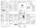
6/1/2008
PATRIOT DOCKS
ASSEMBLY INSTRUCTIONS
Congratulations on your new Patriot Dock purchase. This manual contains instructions to assemble
basic dock configurations for use at typical shoreline application. It is possible to add sections and
combine configurations to the basic configurations as long as installation guidelines are adhered to
(subject to lake and shoreline conditions). Please refer to www.patriotdocks.com for answers to
frequently asked questions and other suggestions.
US Dock and Hardware LLC
Harris, MN
www.usdockandhardware.com www.patriotdocks.com
(651) 674-2450
STRAIGHT SECTIONAL DOCKS
STRAIGHT ROLL-IN DOCKS
ROLL-IN PATIO DOCKS
General Guidelines:
1. Maximum recommended unsupported span for Patriot Aluminum Dock Frames is 16 feet. Always support
outside corners. Use additional posts to add stability as necessary.
2. Always use Patriot Dock Pipe Post Brackets (PN 10810), Post Foot Plates (PN 10811) and 1½ Schedule
40 galvanized pipe (PN 10812-10815) for support posts on Patriot Docks. Installing other parts may result
in an unstable dock or unsafe installation.
3. Always install Vinyl Pipe Caps (PN 10823) on top of support pipes to avoid injury from sharp edges.
4. Never leave the end of the dock unsupported. Always support both corners of the Patio platform. Roll-in
kits should be installed at the very end of the dock for best stability. Additional posts may be required if
roll-in kits are installed at locations other than shown above.
5. Always assemble the dock frame so there is a 4-foot End Rail (PN 10803) at the ends of the dock. For
patio or platform docks, two End Rails are required (may have to be purchased separately). For straight
sectional docks only one End Rail is required. If lateral sections are to be added to the sectional dock (to
form an L-shape), a separate End Rail is not required.
6. When adding lateral frame sections to create an L-shaped configuration (not shown in basic
configurations), install the LAKE end (Connector Rail end) of the added frame towards the straight main
dock. Add two Support Pipes to the end of every lateral section.
7. Install the Pipe Brace Kit PN 10828 in conjunction to the Roll-In Kit for lakes with soft bottoms or deep
water applications. The brace kit will help prevent potential bending of the Support Pipes.
8. Always secure supports posts and level dock before installing deck panels. Remove decking panels
whenever possible when pulling the frame out of the water to prevent bending the dock frame.
9. Maximum recommended distance between wheel kits for long dock applications is 32 feet.
10. Secure poly decking with cable ties as necessary to prevent shifting.
Wear protective gloves. File any sharp edges on pipes and frame to avoid cuts or scrapes.
If you have parts missing, contact your dealer before proceeding. For accessories, replacement parts, FAQ and
warranty information, and detailed assembly directions with hints, please visit www.patriotdocks.com.
TOOLS NEEDED
9/16” and ¾” Wrenches & Ratchet w/Sockets
May Be Required:
Knife Drill with 3/8” Bit
Hammer
Flat File
Phillips Screwdriver or Drill
½” (12mm) Socket
Pliers
COMPONENT IDENTIFICATION
1. The 4’x 8’ Aluminum Truss Frame, PN 10800 includes the following components:
(2) Side Frames
(2) Center Tubes
(1I) Long and (1) Short
(2) Middle Rails
(Same as End Rail PN 10803)
8 ft Diagonal Brace
(1) Connector Rail
(12) 3/8-16 X 1.0 Bolts/Nuts
(6) 3/8-16 X 1.62 Bolts/Nuts
2. The Support Post Assembly, PN 10816 - 10819 includes 1½ Schedule 40 Galvanized Support Pipe available
in 4 ft, 6 ft, 8 ft and 10 ft lengths plus the following components:
(1) Pipe Post Bracket
PN 10810
(1) Post Foot Plate
PN 10811
(1) Vinyl Cap
PN 10823
3. Decking is available in Cedar Drop-in Sections (PN 10870) or in Poly Dock-Top™ Sections (PN10860).
Four molded Dock Tops and at least 6 Deck Clips (PN 10869) are required to assemble each 4x4 Poly DockTop™ Section.
Cedar Deck Section
PN 10870
Poly Dock-Top Section
PN 10860
Deck Clips
PN 10869
4. Various Roll-in Kits are available for Patriot Docks: Shore End Roll-In Kit (PN 10824) with 4-ft axle and 4-ft
posts for shore end or shallow applications; 4’ Wide Roll-In Kit (PN 10825) with 4-ft axle and 6-ft posts for
straight dock applications (note: posts may be ordered longer as necessary); and 8’ Wide Roll-In Kits (PN
10826) with 8-ft axle and 8-ft posts for patio/platform docks. The wheel adds one foot to support height.
Each Roll-in Kit includes 2 Pipe Post Brackets, 2 Support Pipes, Axle Pipe, Wheel Clamps, Washers and Wheels
(1) Axle Converter (pair)
PN 10820
Optional Deep Water Pipe Brace Kit
PN 10828
(1) Wheel Clamp (pair)
PN 10822
(2) Plastic Wheel
PN 10821
Deck Lockers
PN 10867
PATRIOT DOCK ASSEMBLY INSTRUCTIONS:
SHORE END
LAKE END
SHORE END
SHORE END
LAKE END
LAKE END
ASSEMBLE ALUMINUM FRAME:
1. Lay out each 4 ft X 8 ft Aluminum Frame Assembly PN 10800 end to end in the desired basic
configuration on a flat surface.
• Remove each component from the 4 ft X 8 ft Aluminum Frame Assembly packages and unwrap
the protective plastic from the components.
• Place the 8-ft long Side Frame Rails in two lines making sure the ends marked SHORE are
pointing to one direction and the ends marked LAKE are pointed in the opposite direction.
• Place the End and Middle Rails and Connector Rail between the Side Frame Rails as shown.
2. Starting from the left SHORE end of the layout, fasten the 4ft End Frame Rail to the Side Frame Rails
using (4) 3/8 -16 X 1.0 inch bolts and nuts for each. Position each end inside the vertical corner angle of
the Side Frames. Finger-tighten bolts and nuts until all frame components are assembled.
3. Fasten the center 4ft Middle Frame Rail to the Side Frame Rails using (4) 3/8 -16 X 1.0 inch bolts and
nuts. Again, position each end inside the vertical angle on the Side Frames.
4. Position the 4 ft Connector Frame Rail to the Side Frame Rails using (2) 3/8 -16 X 1.625 inch bolts but
do not install the nuts yet. Make sure the welded tab on the Connector Frame Rail faces away from the
assembled frame.
5. Install the Short Center Tube Support between the End and Middle Frame Rails on the SHORE end of
the first 4X8 Frame Rail Assembly and install the Long Center Tube Support between the Middle Frame
Rail and the Connector Rail on the Lake end of the frame assembly. Use (4) 3/8-16 X 1.0 inch bolts and
nuts and (2) 3/8-16 X 1.625 inch bolts and nuts. Note: The (2) longer bolts are passed through the
Connector Rail and the next Middle Frame Rail.
6. Move on to next connecting 4x8 Frame Assembly. Loosely fasten the next set of Side Frame Rails
AND the End Frame Rail of the second frame to the first set of Side Frame Rails using the 3/8-16 X 1.625
inch bolts and nuts in step 4. The Connector Rail of the first Frame Assembly stays in place.
7. Install an additional (2) 3/8 -16 X 1.625 bolts nuts and bolts to secure the bottom of the Side Frame
Rails and Middle Frame Rail.
Note: The End and Middle Frame Rails and Connector Frame Rails are always positioned inside the
welded vertical aluminum angles on the Side Frame Rails.
8. Continue fastening the Side Frames, Middle Frame Rails, Connector Frame Rails and Center Support
Tubes by repeating steps 1-7 until the straight part of the dock frame is assembled. Fasten the final End
Frame Rail PN 10803 (packaged separately) to the Lake end of the dock using (4) 3/8-16 X 1.0 bolts and
nuts. If holes do not match up, use drill with 3/8” bit to size. Discard Lake end Connector Frame Rail.
9. Install diagonal aluminum Brace to the bottom of each Side Frame Rail pair using two 3/8-16 X 1.0 bolts
and nut in an alternating pattern (reverse direction from one 8 ft frame to the next so braces form
continuous zigzag). These can also be installed later for easier access to underside of frame.
10. Patio Docks: Attach 4x8 Frame section to side of last 4x8 Frame using (6) 3/8-16 X 1.625 bolts and
nuts. Make sure to face the SHORE end of the added Patio Frame facing the Shore end of the main dock
frame. Fasten the End Frame Rail PN 10803 (packaged separately) to the Lake end of the dock using (4)
3/8-16 X 1.0 inch bolts and nuts. Discard Lake end Connector Frame Rail. Install ladder uprights now.
11. L-Docks: Lateral sections can only be added to the Lake end of an 8 ft Frame Assembly. The Lake
end or Connector Frame Rail end of the lateral is fastened to the straight main sectional dock after main
dock is placed. For “T”, repeat procedure so that the distance between ends of laterals is 20 ft total.
12. Check to make sure the frame components are flush and tighten all bolted connections with tools.
INSTALL PIPE SUPPORTS AND ROLL-IN KITS:
1. Install Pipe Post Brackets (PN 10810) using ½ - 13 X 1 inch bolts provided as shown on the basic
configuration layouts. The nuts are slipped into the pockets and the shorter bolts fasten the brackets to
the Side Frame Rail. The ½-13 X 1.25 inch bolts are stainless steel and should be screwed into the
weld nuts on the Post Bracket. CAUTION: Maximum span between post supports is 16 feet. Shore
Ramps require support posts at the shore end (use washers for spacers to install these post brackets).
2. Slip Support Pipe (PN 10812-10815) through Pipe Post Brackets and install Foot Plate (PN 10811). For
Roll-In Kits, install Axle Converters (PN 10820) instead of the foot plates, pointing the long part of the
horizontal axle converters towards each other.
3. For Roll-In Kits, slip axle through pipe converters, slide wheels & washers in place and fasten Wheel
Clamps to axle pipe to keep wheels in place. Maintain a 1/8 inch gap between wheel and Axle Converter
when fastening clamp. For straight docks, use 6 ft axle pipe and fasten wheels to the ends of the pipe
outside the dock frame. For Patio Docks, use 8 ft axle pipe and fasten the wheels inside the dock frame
adjacent to the Axle Converters. Tighten bolts ½ turn after bolt contacts pipe. Retighten as necessary.
Add optional Pipe Stabilizer Brace Kit by bolting one end to lower ½ inch diameter hole in welded vertical
angle of dock frame located 4 ft towards shore from the Pipe Brackets for the Roll-In Kit. Use connector
strap to connect other end to vertical pipe support on Roll-In Kit approximately 3 feet below dock frame.
If there is not enough pipe, bolt brace to top hole on vertical angle of dock frame instead.
4. Carefully roll or set the dock in place. Additional helpers may be needed. Adjust pipe supports to level
the dock. Use winch tool, jack, come-along or other means to raise or lower dock. Tighten set bolts on
Pipe Post Brackets. Make sure the long aluminum frame braces are installed on the underside of frame.
5. Install Decking
A) For pre-assembled Cedar Decking Sections, PN 10870, set 4’ x 4’ sections in openings in frame.
B) For pre-assembled poly Dock-Top™ Sections, PN 10860, set 4’ x 4’ sections in openings in frame.
Rotate each Deck Locker (if included) under frame side rails to secure the decking to the dock frame.
Note: To assemble poly panel, lay 4 individual panels upside down (with Dock-Top logos in same
direction) on a flat surface and install 6 Deck Connecting Clips PN 10859 at the panel joints
approximately 12 inches from the edge as indicated below using a hammer. Install 4 or 6 Deck
Lockers PN 10867 between the panels with screws in the pre-drilled holes located about 2-1/4 inches
from the edge (mount with swivel end to outside of panel). Fewer Deck Lockers may be needed when
creating a continuous decking “sheet” where all sections are connected with Deck Connecting Clips on
permanent installations. Secure panels to Shore Ramps with cable ties or screws.
CAUTION: Always secure decking to the frame using cable ties, screws or Deck Lockers.
View Assembly Photos, Hints, and FAQs at www.patriotdocks.com.
LIMITED WARRANTY
US Dock and Hardware LLC provides a limited warranty for plastic Dock-Top™ decking panels to the original purchaser only when
purchased from an authorized dealer. The Dock-Top™ is not warranted in conjunction with other products not manufactured by US Dock
and Hardware LLC.
INTENDED USE: Dock-Top™ panels are intended to be installed on marine docks as decking and are not intended for any other use. The
limited warranty is valid only when used for the intended application. Purchasers should fully inspect each Dock-Top™ panel before
installing.
WARRANTY: Providing that Dock-Top™ are installed as per the instructions supplied, Redtail International LLC warrants that a) DockTop™ will not delaminate; b) Dock-Top™ will not rot; c) Dock-Top™ will not absorb water; d) Dock-Top™ will not degrade from UV rays
(does not include fading or light discoloration); e) Dock-Top™ panels are sold is in accordance with published specifications and are free
of material or workmanship defects.
TERMS: US Dock and Hardware LLC provides a full repair or replacement warranty for the first two years after the purchase date and a
prorated warranty from two to seven years after the date of purchase. The prorated warranty provides replacement at a percentage
discount off the current manufacturer’s suggested retail price (MSRP). US Dock and Hardware LLC may repair, replace or provide a full or
partial refund at its sole discretion according to the following terms. The claimant must present the defective panels to the authorized dealer
from which they were originally purchased along with the original purchase invoice or receipt. The dealer will then submit a warranty claim
to US Dock and Hardware LLC. If US Dock and Hardware LLC certifies that the items are indeed defective, US Dock and Hardware LLC
will repair, replace or provide a prorated discount on replacement of the defective Dock-Top™ panels as follows:
Year 1:
Year 2:
Year 3:
Year 4:
Year 5:
Year 6:
Year 7:
Full Replacement
Full Replacement
Replacement at 50% of MSRP
Replacement at 60% of MSRP
Replacement at 70% of MSRP
Replacement at 80% of MSRP
Replacement at 90% of MSRP
WARRANTY LIMITATIONS: The successful performance of the Dock-Top™ panel is dependant upon many factors beyond our control.
Therefore, except for such replacement or refund outlined above, US Dock and Hardware LLC:
1. MAKES NO WARRANTY OR GUARANTEE, EXPRESS OR IMPLIED, INCLUDING WARRANTIES OF FITNESS, and DESIGN
CAPABILITY OR MERCHANTABILITY RESPECTING ITS PRODUCTS.
2. Under no circumstances shall US Dock and Hardware LLC be liable for any special, incidental or consequential damages including but
not limited to: personal injury, property damage, damage to or loss of product, loss of profits or revenue. The price stated for the products is
a consideration in limiting US Dock and Hardware LLC liability and buyers remedy.
3. This limited warranty shall not apply to any product subject to misuse due to common negligence or accident nor to any product made by
the seller not used in accordance with the printed instructions or specifications of US Dock and Hardware LLC or that have been beyond
the represented and rated capacity of the product.
4. This limited warranty is applicable only to those parties heretofore mentioned, and is not assignable, transferable nor will it insure to the
benefit of any sub-purchaser of the original equipment manufacturer other than the original retail purchaser.
5. Application may be subject to local building codes and is the responsibility of the purchaser to adhere to.
6. As stated above, US Dock and Hardware LLC reserves the right to inspect all panels claimed to be defective or damaged under the
terms of the warranty.
7. US Dock and Hardware LLC limits of warranty is defective material replaced, repaired, or credit against further purchases. All information
and data provided at time of writing is believed to be accurate and complete, however, are provided without any guarantee or responsibility
of any kind, expressed or implied. Suggestions or statements concerning possible use of products are made without representation that
any such use is free from patent infringement and are not recommendations to infringe any patent. The user must be aware that other
safety measures may be required if not stated herein.