1
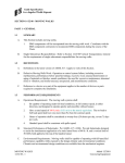
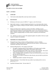
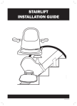
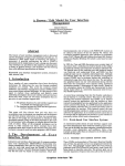
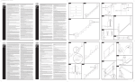
CROSSOVER PRODUCT™
ST R U C T U R A L P OST I N STA L L AT I O N I N ST R U C T I O N S
• Flush-Mount: pp. 2-5
• Fascia (Thru)-Mount: pp. 6-9
• Core-Mount: pp. 10-11
Compatible with
ENDURANCE™ and TITAN PRO™
Railing Systems
FLUSH-MOUNT
POST INSTRUCTIONS
• Determine placement of all structural posts before beginning
installation.
• RDI railing kits are manufactured for a 36”or 42” finished rail
height with a 2” standard bottom space.
COMPONENT LIST:
Check the kit to ensure all components are included.
C
A) Vinyl Shim (2)
B) Extrusion Set Screw (1)
C) Centering Extrusion (2)
B
D) Galvanized Steel Post (1)
A
D
Warning:
Always wear
safety goggles.
2
1.
2.
3.
When installing a structural post in
a flush-mount application, be sure
that sufficient mounting structure
exists to receive the post attachment
fasteners. Install blocking under
surface if necessary.
Determine the rail direction and orient the structural post flange base
accordingly (Fig. 2).
After mounting location is confirmed, pre-drill for permanent
mounting hardware (Fig. 3). Check
and adjust structural post for plumb
using supplied vinyl shims (Fig. 4).
Tip:
Thru-bolting using 3/8” stainless steel
bolts is recommended to attain maximum strength and durability (Fig. 1).
Tip:
When a structural post will act as
the transition point between level
and stair rail at other than a right
angle, be sure to set the post in line
with the stair rail. This will allow the
use of any RDI specialty bracket kit
on the level rail and standard RDI
stair brackets.
Tip:
If using Endurance® Deck Rail™ with
Decorative Cap, please refer to the
instruction booklet included in the
Deck Rail kit (or www.rdirail.com) for
finished post height.
Secure the post through all four
base attachment holes (Fig. 5).
(Fig. 3)
(Fig. 4)
(Fig. 1)
(Fig. 5)
(Fig. 2)
3
4.
5.
6.
Position the lower extrusion aligning
it with the proposed railing direction
(Fig. 6). Ensure that the premounted top centering extrusion is
aligned as well.
Slide the vinyl sleeve over the
centering extrusion. Mark and cut
the sleeve to length.
Slide the vinyl sleeve over the structural post and the centering extrusions (Fig. 10).
Note:
RDI railing kits are manufactured
for a 36" or 42” finished-rail height
with a 2" standard bottom space.
If other heights or bottom spaces
are desired, adjust the height of the
centering extrusion accordingly.
Note:
If installing Endurance® ADA Hand
Rail™ onto a post, determine the
mounting location and create
sufficient attachment by blocking
out post with 1” material or by
purchasing a third centering
extrusion and installing at desired
location (Fig 7).
Tip:
The sleeve should extend above the
desired rail height enough to allow
clearance for a post cap (Fig. 8).
Note:
If using a turned newel sleeve*, be
sure to leave enough flat area to
accept rail attachment brackets
(Fig. 9). Remove the top centering
extrusion set screw and the
extrusion. Use this screw to attach
the bottom centering extrusion to
the post. Slide the top extrusion
onto the post after the turned sleeve
has been installed.
Note:
The top centering extrusion may
need to be repositioned depending
on your application. For example, in
stair railing applications, the centering extrusion may need to be raised
to allow attachment of the stair
brackets.
*Endurance rail kits measure 34” or
40” from the bottom of the bottom
rail to the top of the top rail.
(Fig. 6)
(Fig. 9)
(Fig. 8)
6.5" Minimum
34" or 40" *
(Fig. 7)
4
(Fig. 10)
7.
The post is now ready to accept the
railing installation (Fig. 11).
Note:
Post caps should be glued on
AFTER installation is complete.
Simply apply a small amount of vinyl
adhesive to the cap to permanently
secure.
(Fig. 11)
5
FASCIA (THRU)-MOUNT
POST INSTRUCTIONS
• Determine placement of all structural posts before
beginning installation.
• RDI railing kits are manufactured for a 36” or 42” finished-rail
height with a 2” standard bottom space.
COMPONENT LIST:
Check the kit to ensure all components are included.
C
A) Vinyl Shim (2)
B) Extrusion Set Screw (1)
C) Centering Extrusion (2)
D) Steel Post (1)
B
A
D
Warning:
Always wear
safety goggles.
6
1.
2.
3.
When installing a structural post in
a fascia (thru)-mount application,
be sure that sufficient mounting
structure exists to receive post
attachment fasteners.
Ensuring that the post is plumb from
side-to-side and at the appropriate
height, clamp in place (Fig. 3).
After mounting location is confirmed, pre-drill for permanent
mounting hardware (Fig. 5).
Using the provided vinyl shims,
plumb the post and permanently
secure with at least three mounting
fasteners (Fig. 6,7).
When mounting to a straight face,
three fasteners should be used (Fig.
1). In an inside corner application,
five fasteners should be used to
maximize strength in both directions
(Fig 2).
Note:
Thru-bolting using 3/8” stainless
steel bolts is recommended to attain
maximum strength and durability.
Posts should be installed at a height
of 36” for an RDI residential railing kit
and 42” for an RDI commercial railing
kit.
Using two standard deck screws,
temporarily secure the post in place
through the two smaller holes in the
post (Fig. 4).
Tip:
If using Endurance® Deck Rail™ with
Decorative Cap, please refer to the
instruction booklet included in the
Deck Rail kit (or www.rdirail.com) for
finished post height.
(Fig. 1)
(Fig. 5)
(Fig. 3)
(Fig. 4)
(Fig. 7)
(Fig. 6)
(Fig. 2)
vinyl
shim
7
4.
5.
6.
Position the lower extrusion aligning
it with the proposed railing direction
(Fig. 8). Ensure that the premounted top centering extrusion is
aligned as well.
Slide the vinyl sleeve over the
centering extrusion. Mark and cut
the sleeve to length.
Slide the cut vinyl sleeve
over the structural post and the centering extrusions (Fig. 12).
Tip:
The sleeve should extend above the
desired rail height enough to allow
clearance for a post cap (Fig. 10).
Note:
The top centering extrusion may
need to be repositioned depending
on your application. For example, in
stair rail applications, the centering
extrusion may need to be raised to
allow attachment of the stair brackets.
Note:
In some cases, the vinyl sleeve will
need to be notched to extend below
the plane of the standing surface
to hide the post tail and mounting
hardware (Fig. 13).*Endurance rail
kits measure 34” or 40” from the
bottom of the bottom rail to the top
of the top rail.
Note:
RDI railing kits are manufactured
for a 36” or 42” finished-rail height
with a 2” standard bottom space.
If other heights or bottom spaces
are desired, adjust the height of the
centering extrusion accordingly.
Note:
If installing Endurance® ADA
Hand Rail onto post, determine
the mounting location and create
sufficient attachment by blocking
out post with 1” material or by
purchasing a third centering
extrusion and installing at desired
location (Fig 9).
Note:
If using a turned newel sleeve*, be
sure to leave enough flat area to accept rail attachment brackets (Fig.
11). Remove the top centering extrusion set screw and the extrusion.
Use this screw to attach the bottom
centering extrusion to the post. Slide
the top extrusion onto the post after
the turned sleeve has been installed.
*Endurance rail kits measure 34” or
40” from the bottom of the bottom
rail to the top of the top rail.
(Fig. 8)
(Fig. 12)
(Fig. 11)
(Fig. 10)
(Fig. 9)
6.5" Minimum
34" or 40" *
(Fig. 13)
8
7.
The post is now ready to accept the
railing installation (Fig. 14).
Note:
Post Caps should be glued on AFTER installation is complete.
Simply apply a small amount of vinyl
adhesive to the cap to permanently
secure.
(Fig. 14)
9
CORE-MOUNT POST
INSTRUCTIONS
• Determine placement of all structural posts before beginning
installation.
• RDI railing kits are manufactured for a 36” or 42” finished-rail
height with a 2” standard bottom space.
COMPONENT LIST:
Check the kit to ensure all components are included
C
A) Vinyl Shim (2)
B)Extrusion Set Screw (1)
C)Centering Extrusion (2)
D)Steel Post (1)
B
A
D
Warning:
Always wear
safety goggles.
10
1.
2.
3.
Consult your hydraulic cement
manufacturer’s specifications for
core hole diameter and depth
based on the final railing height for
your installation. After depth and
diameter have been confirmed, drill
and remove the core from the hole
(Fig. 1, 2).
Place the post in the hole and adjust
for plumb (Fig. 3). Temporarily
secure in place using clamps and
wood supports (Fig. 4).
After post has cured, follow the
instructions for RDI flush-mount
structural post, beginning with Step
4. (Fig. 1)
(Fig. 2)
Mix and pour hydraulic cement as
per manufacturer’s instructions (Fig.
5).
(Fig. 3)
(Fig. 4)
(Fig. 5)
11
RAILING DYNAMICS, INC.
FOR HOME, FOR LIFE.™
135 STEELMANVILLE ROAD
EGG HARBOR TOWNSHIP, NJ 08234
TEL: (877) 420-7245
FAX: (866) 277-5160
E-MAIL: [email protected]
URL: WWW.RDIRAIL.COM
EMISP/4.11