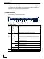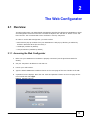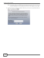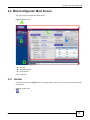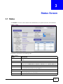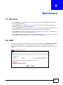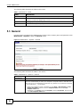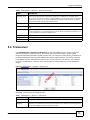
1
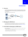
PMG1006-B20A
GPON SFU with 4-port GbE Switch
Version 1.00
Edition 1, 9/2013
Quick Start Guide
User’s Guide
Default Login Details
LAN IP Address
http://192.168.1.1
User Name
www.zyxel.com
Password
admin
1234
Copyright © 2013 ZyXEL Communications Corporation
IMPORTANT!
READ CAREFULLY BEFORE USE.
KEEP THIS GUIDE FOR FUTURE REFERENCE.
Screenshots and graphics in this book may differ slightly from your product due to differences in
your product firmware or your computer operating system. Every effort has been made to ensure
that the information in this manual is accurate.
Related Documentation
• Quick Start Guide
The Quick Start Guide shows how to connect the GPON Device and get up and running right
away.
2
PMG1006-B20A User’s Guide
Table of Contents
Table of Contents
Table of Contents .................................................................................................................................3
Chapter 1
Introduction...........................................................................................................................................5
1.1 Overview .............................................................................................................................................5
1.2 Managing the GPON Device ...............................................................................................................5
1.3 Good Habits for Managing the GPON Device .....................................................................................5
1.4 LEDs (Lights) ......................................................................................................................................6
1.5 The Reset Button ................................................................................................................................7
1.5.1 Using the Reset Button ..............................................................................................................7
Chapter 2
The Web Configurator ..........................................................................................................................9
2.1 Overview ............................................................................................................................................9
2.1.1 Accessing the Web Configurator ...............................................................................................9
2.2 Web Configurator Main Screen ......................................................................................................... 11
2.2.1 Title Bar ................................................................................................................................... 11
2.2.2 Navigation Panel .....................................................................................................................12
2.2.3 Main Window ...........................................................................................................................12
2.2.4 Status Bar ................................................................................................................................12
Chapter 3
Status Screen ......................................................................................................................................13
3.1 Status ................................................................................................................................................13
Chapter 4
LAN ......................................................................................................................................................15
4.1 Overview ..........................................................................................................................................15
4.2 IP .......................................................................................................................................................15
Chapter 5
Maintenance ........................................................................................................................................17
5.1 Overview ...........................................................................................................................................17
5.2 SLID .................................................................................................................................................17
5.3 General
...........................................................................................................................................18
5.4 Transceiver .......................................................................................................................................19
5.5 View Log ...........................................................................................................................................20
5.6 Log Settings .....................................................................................................................................21
5.7 Tools Screens Overview ....................................................................................................................22
PMG1006-B20A User’s Guide
3
Table of Contents
5.7.1 Some Warnings .......................................................................................................................22
5.8 Firmware
.........................................................................................................................................22
5.9 Configuration ....................................................................................................................................24
5.9.1 Backup Configuration .............................................................................................................24
5.9.2 Restore Configuration .............................................................................................................25
5.9.3 Reset to Factory Defaults .......................................................................................................25
5.10 Restart .............................................................................................................................................25
Chapter 6
Troubleshooting..................................................................................................................................27
6.1 Overview ...........................................................................................................................................27
6.2 Power, Hardware Connections, and LEDs ........................................................................................27
6.3 GPON Device Access and Login ......................................................................................................28
6.4 Internet Access .................................................................................................................................29
Appendix A Legal Information............................................................................................................31
Index ....................................................................................................................................................33
4
PMG1006-B20A User’s Guide
C HAPT ER
1
Introduction
1.1 Overview
The PMG1006-B20A SFU (Single Family Unit) combines a fiber optic GPON (Gigabit Passive Optical
Network) ONT (Optical Network Terminal) with a built-in 4-port Gigabit Ethernet switch. Your GPON
Device provides shared Internet access through a fiber optic line connected to the PON port’s builtin optical transceiver.
Figure 1 GPON Device Providing Internet Access
Fiber
Internet
Gb Ethernet
1.2 Managing the GPON Device
Use the GPON Device’s built-in Web Configurator to manage it. You can connect to it using a web
browser such as Firefox or Internet Explorer. The Web Configurator gives you access to all the
available settings for this product. For details on connecting to it, see the Section 2.1.1 on page 9.
1.3 Good Habits for Managing the GPON Device
Do the following things regularly to make the GPON Device more secure and to manage the GPON
Device more effectively.
• Change the password. Use a password that’s not easy to guess and that consists of different
types of characters, such as numbers and letters.
• Write down the password and put it in a safe place.
PMG1006-B20A User’s Guide
5
Chapter 1 Introduction
• Back up the configuration (and make sure you know how to restore it). Restoring an earlier
working configuration may be useful if the GPON Device becomes unstable or even crashes. If
you forget your password, you will have to reset the GPON Device to its factory default settings.
If you backed up an earlier configuration file, you would not have to totally re-configure the
GPON Device. You could simply restore your last configuration.
1.4 LEDs (Lights)
The following graphic displays the labels of the LEDs.
Figure 2 LEDs on the Top Panel
None of the LEDs are on if the GPON Device is not receiving power.
Table 1 LED Descriptions
LED
COLOR
STATUS
DESCRIPTION
POWER
Green
On
The GPON Device is receiving power and is ready for use.
Off
The GPON Device is not receiving power or has malfunctioned.
Green
On
The GPON Device has a PON line connection.
Orange
On
The GPON Device’s PON port is physically connected but not registered.
Red
On
The GPON Device’s PON port is not connected. The optical transceiver may
have malfunctioned or the fiber cable may not be connected or may be
broken or damaged enough to break the PON connection.
ALARM
Red
On
An equipment failure has occurred.
Off
The GPON Device has not detected an equipment failure.
10/100/
100 1~4
Orange
On
The GPON Device has a 1 Gb Ethernet connection with another device
(such as a computer) on the Local Area Network (LAN) through this port.
Blinking
The GPON Device is sending/receiving data to/from the LAN through this
port.
On
The GPON Device has a 100 Mb Ethernet connection with another device
on the LAN through this port.
Blinking
The GPON Device is sending/receiving data to/from the LAN through this
port.
On
The GPON Device has a 10 Mb Ethernet connection with another device on
the LAN through this port.
Blinking
The GPON Device is sending/receiving data to/from the LAN through this
port.
Off
The GPON Device does not have an Ethernet connection with the LAN
through this port.
Green
On
The Ethernet port has a full duplex connection.
Orange
On
The Ethernet port has a half duplex connection.
PON
Green
Red
DUPLEX
1~4
6
PMG1006-B20A User’s Guide
Chapter 1 Introduction
1.5 The Reset Button
If you forget your password or cannot access the Web Configurator, you will need to use the RESET
button at the back of the GPON Device to reload the factory-default configuration file. This means
that you will lose all custom configuration and the password will be reset to the default.
1.5.1 Using the Reset Button
1
Make sure the POWER LED is on (not blinking).
2
To set the GPON Device back to the factory default settings, press the RESET button for more than
three seconds and then release it. The LEDs flash and the GPON Device restores the defaults and
restarts.
Note: Press the RESET button for less than one second to restart the GPON Device
without changing it back to the factory default settings.
PMG1006-B20A User’s Guide
7
Chapter 1 Introduction
8
PMG1006-B20A User’s Guide
C HAPT ER
2
The Web Configurator
2.1 Overview
The Web Configurator is an HTML-based management interface that allows easy GPON Device setup
and management via Internet browser. Use Internet Explorer 8.0 and later or Firefox 23.0.0 and
later versions. The recommended screen resolution is 1024 by 768 pixels.
In order to use the Web Configurator you need to allow:
• Web browser pop-up windows from your GPON Device. Web pop-up blocking is enabled by
default in Windows XP SP (Service Pack) 2.
• JavaScript (enabled by default).
• Java permissions (enabled by default).
2.1.1 Accessing the Web Configurator
1
Make sure your GPON Device hardware is properly connected (see the Quick Start Guide for
details).
2
Set your computer’s IP address to 192.168.1.5.
3
Launch your web browser.
4
Type the default GPON Device address shown on the cover page of this User’s Guide as the URL.
5
A password screen displays. Enter the user name and password shown on the cover page of this
User’s Guide and click Login.
Figure 3 Password Screen
PMG1006-B20A User’s Guide
9
Chapter 2 The Web Configurator
Note: For security reasons, the GPON Device automatically logs you out if you do not use
the Web Configurator for an extended period of time. If this happens, log in again.
6
Use the next screen to change your password. Make sure you write your new password down and
store it in a safe place. Click Apply.
Figure 4 Change Password Screen
10
PMG1006-B20A User’s Guide
Chapter 2 The Web Configurator
2.2 Web Configurator Main Screen
The main screen is divided into these parts:
Figure 5 Main Screen
A
C
B
D
• A - title bar
• B - navigation panel
• C - main window
• D - status bar
2.2.1 Title Bar
The title bar provides a Logout icon in the upper right corner. Click this icon to log out of the Web
Configurator.
Figure 6 Logout Icon
PMG1006-B20A User’s Guide
11
Chapter 2 The Web Configurator
2.2.2 Navigation Panel
The following table describes the menu items on the navigation panel.
Table 2 Navigation Panel Summary
LINK
TAB
Status
FUNCTION
This screen shows the GPON Device’s general device and interface status
information.
Network
LAN
IP
Use this screen to configure your GPON Device’s LAN IP address and subnet
mask.
SLID
SLID
Use this screen to change your GPON Device’s Subscriber Location ID (SLID)
setting. The SLID identifies your device to the GPON service provider.
System
General
Use this screen to configure your GPON Device’s name, management
inactivity timeout, and password.
Transceiver
Use this screen to view current status information for the GPON Device’s
optical transceiver and configure transceiver alarm thresholds.
View Log
Use this screen to display your GPON Device’s logs.
Log Settings
Use this screen to select which logs the GPON Device records.
Firmware
Use this screen to upload firmware to your GPON Device.
Configuration
Use this screen to backup and restore your GPON Device’s configuration
(settings) or reset the factory default settings.
Restart
Use this screen to reboot the GPON Device without turning the power off.
Maintenance
Logs
Tools
2.2.3 Main Window
The main window displays information and configuration fields. It is discussed in the rest of this
document. The Status screen displays after you log in. See Chapter 3 on page 13 for details about
the Status screen.
2.2.4 Status Bar
Check the status bar when you click Apply or OK to verify that the configuration has been updated.
12
PMG1006-B20A User’s Guide
C HAPT ER
3
Status Screen
3.1 Status
Click Status to see the current status of the GPON Device, its system resources, and interfaces.
Figure 7 Status
Each field is described in the following table.
Table 3 Status
LABEL
DESCRIPTION
Refresh Interval
Select how often you want the GPON Device to update this screen from the drop-down
list box.
Device Information
Host Name
This field displays the GPON Device system name. It is used for identification. You can
change this in the Maintenance > System > General screen’s System Name field.
Model Number
This is the model name of the GPON Device.
Firmware Version
This field displays the current version of the firmware inside the GPON Device. Click
this to go to the screen where you can change it.
LAN Information
IP Address
This field displays the current IP address of the GPON Device in the LAN. Click this to
go to the screen where you can change it.
IP Subnet Mask
This field displays the GPON Device’s LAN subnet mask.
PMG1006-B20A User’s Guide
13
Chapter 3 Status Screen
Table 3 Status (continued)
LABEL
MAC Address
DESCRIPTION
This is the LAN interface MAC (Media Access Control) address unique to your GPON
Device. The MAC address uses six pairs of hexadecimal notation and follows an
industry standard that ensures no other adapter has the same address.
Transceiver Status
Temperature
This displays the transceiver’s temperature in Celsius. The normal range is 0-70
degrees.
Voltage
This displays the transceiver’s voltage in Volts. The normal range is 3.13-3.47 Volts.
Bias Current
This displays the transceiver’s bias current in mA. The normal range is 4-50 mA.
Optical Tx Power
This displays the transceiver’s optical transmitting power in dBm. The normal range is
.5 to 5 dBm.
Optical Rx Power
This displays the transceiver’s optical receiving power in dBm. The normal range is -6
to -28 dBm.
System Status
System Uptime
This field displays how long the GPON Device has been running since it last started up.
The GPON Device starts up when you turn it on, when you restart it (Maintenance >
Tools > Restart), or when you reset it.
CPU Usage
This field displays what percentage of the GPON Device’s processing ability is currently
used. When this percentage is close to 100%, the GPON Device is running at full load,
and the throughput is not going to improve anymore. If you want some applications to
have more throughput, you should turn off other applications.
Memory Usage
This field displays what percentage of the GPON Device’s memory is currently used.
Usually, this percentage should not increase much. If memory usage gets close to
100%, the GPON Device is probably becoming unstable. Restart it (see Section 5.10
on page 25, or turn it off for a few seconds.
Interface Status
14
Interface
This column identifies the interface on the GPON Device.
Status
This field displays Up when the interface has a connection and Down when it does
not.
Rate
This field displays the connection speed of the WAN interface’s PON connection when it
is connected. This field displays the connection speed and duplex for a connected LAN
interface.
PMG1006-B20A User’s Guide
C HAPT ER
4
LAN
4.1 Overview
This chapter describes how to configure LAN settings.
A Local Area Network (LAN) is a shared communication system to which many computers are
attached. A LAN is a computer network limited to the immediate area, usually the same building or
floor of a building.
4.2 IP
Click Network > LAN to open the IP screen. Use this screen to set the Local Area Network IP
address and subnet mask of your GPON Device.
Figure 8 Network > LAN > IP
The following table describes the fields in this screen.
Table 4 Network > LAN > IP
LABEL
DESCRIPTION
IP Address
Enter the LAN IP address you want to assign to your GPON Device in dotted decimal
notation, for example, 192.168.1.1 (factory default).
IP Subnet Mask
Type the subnet mask of your network in dotted decimal notation, for example
255.255.255.0 (factory default). Your GPON Device automatically computes the
subnet mask based on the IP address you enter, so do not change this field unless you
are instructed to do so.
Apply
Click Apply to save your changes back to the GPON Device.
Cancel
Click Cancel to begin configuring this screen afresh.
PMG1006-B20A User’s Guide
15
Chapter 4 LAN
16
PMG1006-B20A User’s Guide
C HAPT ER
5
Maintenance
5.1 Overview
• Use the SLID screen (see Section 5.2 on page 17) to change your GPON Device’s Subscriber
Location ID (SLID) setting.
• Use the General screen (see Section 5.3 on page 18) to configure your GPON Device’s name,
management inactivity timeout, and password.
• Use the Transceiver screen (see Section 5.4 on page 19) to view current status information for
the GPON Device’s optical transceiver and configure transceiver alarm thresholds.
• Use the Logs screens (see Section 5.5 on page 20 and Section 5.6 on page 21) to display your
GPON Device’s logs and select which logs to record.
• Use the Tools screens (see Section 5.7 on page 22 through Section 5.10 on page 25) to upload
new firmware, manage configuration files and restart your GPON Device.
5.2 SLID
To change your GPON Device’s Subscriber Location ID (SLID) setting, click Maintenance > SLID.
The screen appears as shown. The SLID identifies your device to the GPON service provider’s
Optical Line Terminal (OLT). If your GPON service provider gave you an SLID to use, enter it in this
screen.
Figure 9 Maintenance > SLID
PMG1006-B20A User’s Guide
17
Chapter 5 Maintenance
The following table describes the fields in this screen.
Table 5 Maintenance > SLID
LABEL
DESCRIPTION
Enable SLID
Select this to have the GPON Device use the SLID to identify itself to the OLT.
SLID Value
Enter the SLID used for gaining access to the service provider’s network. It is casesensitive, so make sure [Caps Lock] is not on.
Apply
Click Apply to save your changes back to the GPON Device.
Cancel
Click Cancel to begin configuring this screen afresh.
5.3 General
Use this screen to configure the GPON Device’s system name, inactivity timer, and password. Click
Maintenance > System to open the General screen.
Figure 10 Maintenance > System > General
The following table describes the labels in this screen.
Table 6 Maintenance > System > General
LABEL
DESCRIPTION
General Setup
System Name
Choose a descriptive name for identification purposes. Because some ISPs check this
name it is recommended you enter your computer’s “Computer name” in this field. This
name can be up to 30 alphanumeric characters long. Spaces are not allowed, but dashes
“-” and underscores "_" are accepted.
•
•
18
To find your computer’s name in Windows XP, click Start > My Computer > View
system information and then click the Computer Name tab. See the Full
computer name field.
In Windows 7, click Start, right click Computer, and click Properties. See the entry
in the Full computer name field.
PMG1006-B20A User’s Guide
Chapter 5 Maintenance
Table 6 Maintenance > System > General (continued)
LABEL
DESCRIPTION
Administrator
Inactivity Timer
Type how many minutes a management session (either via the Web Configurator or
telnet) can be left idle before the session times out. The default is 5 minutes. After it
times out you have to log in with your password again. Very long idle timeouts may have
security risks. A value of "0" means a management session never times out, no matter
how long it has been left idle (not recommended).
Password
Old Password
Type the default password or the existing password you use to access the system in this
field.
New Password
Type your new system password (up to 30 characters). Note that as you type a password,
the screen displays a (*) for each character you type. After you change the password, use
the new password to access the GPON Device.
Retype to Confirm
Type the new password again for confirmation.
Apply
Click Apply to save your changes back to the GPON Device.
Cancel
Click Cancel to begin configuring this screen afresh.
5.4 Transceiver
Click Maintenance > System > Transceiver to view your GPON Device’s current transceiver
status and configure alarm thresholds. The optical SFP transceiver’s support for the Digital
Diagnostics Monitoring Interface (DDMI) function lets you monitor the transceiver’s parameters to
perform component monitoring, fault isolation and failure prediction tasks. This allows proactive,
preventative network maintenance to help ensure service continuity. The values in the following
figure are an example for reference only. See the table for details about the normal parameter
ranges.
EX
A
M
PL
E
Figure 11 Maintenance > System > Transceiver
Each field is described in the following table.
Table 7 Maintenance > System > Transceiver
LABEL
DESCRIPTION
Current Value
This column displays the current status for each monitored DDMI parameter.
High Alarm
Threshold
Use this column to set the high value alarm threshold for each monitored DDMI
parameter. The GPON Device reports an alarm signal to the Optical Line Terminal (OLT) if
the monitored DDMI parameter reaches this value.
PMG1006-B20A User’s Guide
19
Chapter 5 Maintenance
Table 7 Maintenance > System > Transceiver (continued)
LABEL
DESCRIPTION
Low Alarm
Threshold
Use this column to set the low value alarm threshold for each monitored DDMI parameter.
The GPON Device reports an alarm signal to the Optical Line Terminal (OLT) if the
monitored DDMI parameter reaches this value.
Temperature
(Celsius)
The transceiver's temperature in Celsius. The normal range is 0-70 degrees.
Voltage (Volts)
The transceiver's voltage in Volts. The normal range is 3.13-3.47 Volts.
Bias Current
(milliAmperes)
The transceiver's bias current in mA. The normal range is 4-50 mA.
Optical Transmit
Power (dBm)
The transceiver's optical transmitting power in dBm. The normal range is .5 to 5 dBm. N/
A displays when the PON port is not connected.
Optical Receive
Power (dBm)
The transceiver's optical receiving power in dBm. The normal range is -6 to -28 dBm. N/A
displays when the PON port is not connected.
Apply
Click Apply to save your changes back to the GPON Device.
Cancel
Click Cancel to begin configuring this screen afresh.
5.5 View Log
Click Maintenance > Logs to open the View Log screen. Use this screen to see the logs for the
categories that you selected in the Log Settings screen (see Section 5.6 on page 21).
Log entries in red indicate alerts. The log wraps around and deletes the old entries after it fills. Click
a column heading to sort the entries. A triangle indicates ascending or descending sort order.
Figure 12 Maintenance > Logs > View Log
20
PMG1006-B20A User’s Guide
Chapter 5 Maintenance
The following table describes the fields in this screen.
Table 8 Maintenance > Logs > View Log
LABEL
DESCRIPTION
Display
The categories that you select in the Log Settings screen display in the drop-down list box.
Select a category of logs to view; select All Logs to view logs from all of the log categories
that you selected in the Log Settings page.
Refresh
Click Refresh to renew the log screen.
Clear Log
Click Clear Log to delete all the logs.
#
This field is a sequential value and is not associated with a specific entry.
Time
This field displays the time the log was recorded.
Facility
This indicates the type of connection to the GPON Device.
Level
This indicates the log severity.
Message
This field states the reason for the log.
First
Click this to cycle to the first page of logs.
Previous
Click this to cycle to the previous page of logs.
Page
This indicates which page you are on, out of how many. You can enter a page number here
and press [Enter] to jump directly to that page.
Next
Click this to cycle to the next page of logs.
Last
Click this to cycle to the last page of logs
Refresh
Click this to refresh the logs screen.
5.6 Log Settings
Use this screen to configure which logs to display on the View Logs screen (see Section 5.5 on
page 20). Click Maintenance > Logs > Log Settings.
Figure 13 Maintenance > Logs > Log Settings
The following table describes the fields in this screen.
Table 9 Maintenance > Logs > Log Settings
LABEL
DESCRIPTION
Active Log
[Log Type]
PMG1006-B20A User’s Guide
Select the type of log you want to be displayed on the View Logs screen.
21
Chapter 5 Maintenance
Table 9 Maintenance > Logs > Log Settings
LABEL
DESCRIPTION
Apply
Click Apply to save your customized settings and exit this screen.
Cancel
Click Cancel to return to the previously saved settings.
5.7 Tools Screens Overview
Use the Tools screens to upload new firmware, manage configuration files and restart your GPON
Device.
Use the instructions in this chapter to change the GPON Device’s configuration file or upgrade its
firmware. After you configure your GPON Device, you can backup the configuration file to a
computer. That way if you later misconfigure the GPON Device, you can upload the backed up
configuration file to return to your previous settings. You can alternately upload the factory default
configuration file if you want to return the GPON Device to the original default settings. The
firmware determines the GPON Device’s available features and functionality.
5.7.1 Some Warnings
The following are some friendly reminders about your GPON Device:
Do NOT turn off the GPON Device while a firmware upload is in progress!
Only use firmware for your specific model. Refer to the label on the
bottom of your GPON Device.
5.8 Firmware
Click Maintenance > Tools to open the Firmware screen. Follow the instructions in this screen to
upload firmware to your GPON Device. The upload process uses HTTP (Hypertext Transfer Protocol)
and may take up to two minutes. After a successful upload, the system will reboot.
Figure 14 Maintenance > Tools > Firmware
22
PMG1006-B20A User’s Guide
Chapter 5 Maintenance
The following table describes the labels in this screen.
Table 10 Maintenance > Tools > Firmware
LABEL
DESCRIPTION
Firmware Upgrade
Current Firmware
Version
This is the present Firmware version and the date created.
File Path
Type in the location of the file you want to upload in this field or click Browse ... to find it.
Browse...
Click Browse... to find the .bin file you want to upload. Remember that you must
decompress compressed (.zip) files before you can upload them.
Upload
Click Upload to begin the upload process. This process may take up to two minutes.
After you see the Firmware Upload in Progress screen, wait three minutes before logging into
the GPON Device again.
The GPON Device automatically restarts in this time causing a temporary network disconnect.
After two minutes, log in again and check your new firmware version in the Status screen.
If the upload was not successful, the following screen will appear. Click Return to go back to the
Firmware screen.
PMG1006-B20A User’s Guide
23
Chapter 5 Maintenance
5.9 Configuration
Click Maintenance > Tools > Configuration. Information related to factory defaults, backup
configuration, and restoring configuration appears in this screen, as shown next.
Figure 15
Maintenance > Tools > Configuration
5.9.1 Backup Configuration
Backup Configuration allows you to back up (save) the GPON Device’s current configuration to a file
on your computer. Once your GPON Device is configured and functioning properly, it is highly
recommended that you back up your configuration file before making configuration changes. The
backup configuration file will be useful in case you need to return to your previous settings.
Click Backup to save the GPON Device’s current configuration to your computer.
24
PMG1006-B20A User’s Guide
Chapter 5 Maintenance
5.9.2 Restore Configuration
Restore Configuration allows you to upload a new or previously saved configuration file from your
computer to your GPON Device.
Table 11 Restore Configuration
LABEL
DESCRIPTION
File Path
Type in the location of the file you want to upload in this field or click Browse ... to find it.
Browse...
Click Browse... to find the file you want to upload. Remember that you must decompress
compressed (.ZIP) files before you can upload them.
Upload
Click Upload to begin the upload process.
After you see a “restore configuration successful” screen, you must then wait one minute before
logging into the GPON Device again.
The GPON Device automatically restarts in this time causing a temporary network disconnect.
If you uploaded the default configuration file you may need to change the IP address of your
computer to be in the same subnet as the default GPON Device IP address shown on the cover.
If the upload was not successful, the following screen will appear. Click Return to go back to the
Configuration screen.
5.9.3 Reset to Factory Defaults
Click the Reset button to clear all user-entered configuration information and return the GPON
Device to its factory defaults. You can also press the RESET button on the rear panel to reset the
factory defaults of your GPON Device (see Section 1.5 on page 7 for details).
5.10 Restart
System restart allows you to reboot the GPON Device without turning the power off. Click
Maintenance > Tools > Restart. Click Restart to have the GPON Device reboot. This does not
affect the GPON Device's configuration.
Figure 16 Maintenance > Tools > Restart
PMG1006-B20A User’s Guide
25
Chapter 5 Maintenance
26
PMG1006-B20A User’s Guide
C HAPT ER
6
Troubleshooting
6.1 Overview
This chapter offers some suggestions to solve problems you might encounter. The potential
problems are divided into the following categories.
• Power, Hardware Connections, and LEDs
• GPON Device Access and Login
• Internet Access
6.2 Power, Hardware Connections, and LEDs
The GPON Device does not turn on. None of the LEDs turn on.
1
Make sure the GPON Device is turned on.
2
Make sure you are using the power adaptor or cord included with the GPON Device.
3
Make sure the power adaptor or cord is connected to the GPON Device and plugged in to an
appropriate power source. Make sure the power source is turned on.
4
Turn the GPON Device off and on.
5
If the problem continues, contact the vendor.
One of the LEDs does not behave as expected.
1
Make sure you understand the normal behavior of the LED. The PON LED turns red if the optical
transceiver has malfunctioned or the fiber cable is not connected or is broken or damaged enough
to break the PON connection. See Section 1.4 on page 6 for details about the other LEDs.
2
Check the hardware connections. See the Quick Start Guide for details.
3
Inspect your cables for damage. Contact the vendor to replace any damaged cables.
4
Turn the GPON Device off and on.
PMG1006-B20A User’s Guide
27
Chapter 6 Troubleshooting
5
If the problem continues, contact the vendor.
6.3 GPON Device Access and Login
I forgot the IP address for the GPON Device.
1
The default IP address is 192.168.1.1.
2
If you changed the IP address and have forgotten it, reset the GPON Device to its factory defaults.
See Section 1.5 on page 7.
I cannot see or access the Login screen in the Web Configurator.
1
Make sure you are using the correct IP address.
• The default IP address is 192.168.1.1.
• If you changed the IP address, use the new IP address.
• If you changed the IP address and have forgotten it, reset the GPON Device to its factory
defaults. See Section 1.5 on page 7.
2
Check the hardware connections, and make sure the LEDs are behaving as expected. See Section
1.4 on page 6.
3
Make sure your Internet browser does not block pop-up windows and has Javascript and Java
enabled.
4
Reset the GPON Device to its factory defaults, and try to access the GPON Device with the default
IP address. See Section 1.5 on page 7.
5
If the problem continues, contact the network administrator or vendor.
I can see the Login screen, but I cannot log in to the GPON Device.
28
1
Make sure you have entered the user name and password correctly. The default user name is
shown on the cover page of this User’s Guide. These fields are case-sensitive, so make sure [Caps
Lock] is not on.
2
You cannot log in to the Web Configurator while someone is using Telnet to access the GPON
Device. Log out of the GPON Device in the other session, or ask the person who is logged in to log
out.
3
Turn the GPON Device off for ten seconds and then back on.
PMG1006-B20A User’s Guide
Chapter 6 Troubleshooting
4
If this does not work, you have to reset the GPON Device to its factory defaults. See Section 1.5 on
page 7.
6.4 Internet Access
I cannot access the Internet.
1
Check the hardware connections, and make sure the LEDs are behaving as expected.
The PON LED turns red if the optical transceiver has malfunctioned or the fiber cable is not
connected or is broken or damaged enough to break the PON connection.
The PON LED turns orange if the GPON Device’s PON port is physically connected but not
registered. If the service provider gave you an SLID to use, make sure you entered the SLID
correctly (see Section 5.2 on page 17). It is case-sensitive, so make sure [Caps Lock] is not on.
See Section 1.4 on page 6 for details about the other LEDs.
2
Make sure you entered the ISP account information correctly in your computer. These fields are
case-sensitive, so make sure [Caps Lock] is not on.
3
Disconnect all the cables from your GPON Device, and follow the directions in the Quick Start Guide
again.
4
If the problem continues, contact the ISP.
I cannot access the Internet anymore. I had access to the Internet (with the GPON Device),
but my Internet connection is not available anymore.
1
Check the hardware connections, and make sure the LEDs are behaving as expected. The PON LED
turns red if the optical transceiver has malfunctioned or the fiber cable is not connected or is broken
or damaged enough to break the PON connection. See Section 1.4 on page 6 for details about the
other LEDs.
2
Turn the GPON Device off and on.
3
If the problem appears to be the GPON Device, contact the ISP.
The Internet connection is slow or intermittent.
1
There might be a lot of traffic on the network. Look at the LEDs (see Section 1.4 on page 6). If the
GPON Device is sending or receiving a lot of information, try closing some programs that use the
Internet, especially peer-to-peer applications.
PMG1006-B20A User’s Guide
29
Chapter 6 Troubleshooting
30
2
Turn the GPON Device off and on.
3
If the problem continues, contact the network administrator or vendor.
PMG1006-B20A User’s Guide
A PPENDIX
A
Legal Information
Copyright
Copyright © 2013 by ZyXEL Communications Corporation.
The contents of this publication may not be reproduced in any part or as a whole, transcribed, stored in a retrieval system, translated into
any language, or transmitted in any form or by any means, electronic, mechanical, magnetic, optical, chemical, photocopying, manual, or
otherwise, without the prior written permission of ZyXEL Communications Corporation.
Published by ZyXEL Communications Corporation. All rights reserved.
Disclaimer
ZyXEL does not assume any liability arising out of the application or use of any products, or software described herein. Neither does it
convey any license under its patent rights nor the patent rights of others. ZyXEL further reserves the right to make changes in any
products described herein without notice. This publication is subject to change without notice.
Trademarks
Trademarks mentioned in this publication are used for identification purposes only and may be properties of their respective owners.
Certifications
Federal Communications Commission (FCC) Interference Statement
This device has been tested and found to comply with the limits for a Class B digital device pursuant to Part 15 of the FCC Rules. These
limits are designed to provide reasonable protection against harmful interference in a residential installation. This device generates, uses,
and can radiate radio frequency energy, and if not installed and used in accordance with the instructions, may cause harmful interference
to radio communications. However, there is no guarantee that interference will not occur in a particular installation.
If this device does cause harmful interference to radio/television reception, which can be determined by turning the device off and on, the
user is encouraged to try to correct the interference by one or more of the following measures:
1
2
3
4
Reorient or relocate the receiving antenna.
Increase the separation between the equipment and the receiver.
Connect the equipment into an outlet on a circuit different from that to which the receiver is connected.
Consult the dealer or an experienced radio/TV technician for help.
Notices
Changes or modifications not expressly approved by the party responsible for compliance could void the user's authority to operate the
equipment.
Viewing Certifications
Go to http://www.zyxel.com to view this product’s documentation and certifications.
ZyXEL Limited Warranty
ZyXEL warrants to the original end user (purchaser) that this product is free from any defects in material or workmanship for a specific
period (the Warranty Period) from the date of purchase. The Warranty Period varies by region. Check with your vendor and/or the
authorized ZyXEL local distributor for details about the Warranty Period of this product. During the warranty period, and upon proof of
purchase, should the product have indications of failure due to faulty workmanship and/or materials, ZyXEL will, at its discretion, repair or
replace the defective products or components without charge for either parts or labor, and to whatever extent it shall deem necessary to
restore the product or components to proper operating condition. Any replacement will consist of a new or re-manufactured functionally
equivalent product of equal or higher value, and will be solely at the discretion of ZyXEL. This warranty shall not apply if the product has
been modified, misused, tampered with, damaged by an act of God, or subjected to abnormal working conditions.
Note
Repair or replacement, as provided under this warranty, is the exclusive remedy of the purchaser. This warranty is in lieu of all other
warranties, express or implied, including any implied warranty of merchantability or fitness for a particular use or purpose. ZyXEL shall in
no event be held liable for indirect or consequential damages of any kind to the purchaser.
To obtain the services of this warranty, contact your vendor. You may also refer to the warranty policy for the region in which you bought
the device at http://www.zyxel.com/web/support_warranty_info.php.
Registration
Register your product online to receive e-mail notices of firmware upgrades and information at www.zyxel.com for global products, or at
www.us.zyxel.com for North American products.
PMG1006-B20A User’s Guide
31
Appendix A Legal Information
Open Source Licenses
This product contains in part some free software distributed under GPL license terms and/or GPL like licenses. Open source licenses are
provided with the firmware package. You can download the latest firmware at www.zyxel.com. To obtain the source code covered under
those Licenses, please contact [email protected] to get it.
Safety Warnings
•
•
•
•
•
•
•
•
•
•
•
•
•
•
•
•
•
•
•
To avoid possible eye injury, do NOT look into an operating fiber-optic module’s connector.
Do NOT use this product near water, for example, in a wet basement or near a swimming pool.
Do NOT expose your device to dampness, dust or corrosive liquids.
Do NOT store things on the device.
Do NOT install, use, or service this device during a thunderstorm. There is a remote risk of electric shock from lightning.
Connect ONLY suitable accessories to the device.
Do NOT open the device or unit. Opening or removing covers can expose you to dangerous high voltage points or other risks. ONLY
qualified service personnel should service or disassemble this device. Please contact your vendor for further information.
Make sure to connect the cables to the correct ports.
Place connecting cables carefully so that no one will step on them or stumble over them.
Always disconnect all cables from this device before servicing or disassembling.
Use ONLY an appropriate power adaptor or cord for your device. Connect it to the right supply voltage (for example, 110V AC in North
America or 230V AC in Europe).
Do NOT allow anything to rest on the power adaptor or cord and do NOT place the product where anyone can walk on the power
adaptor or cord.
Do NOT use the device if the power adaptor or cord is damaged as it might cause electrocution.
If the power adaptor or cord is damaged, remove it from the device and the power source.
Do NOT attempt to repair the power adaptor or cord. Contact your local vendor to order a new one.
Do not use the device outside, and make sure all the connections are indoors. There is a remote risk of electric shock from lightning.
Do NOT obstruct the device ventilation slots, as insufficient airflow may harm your device.
If you wall mount your device, make sure that no electrical lines, gas or water pipes will be damaged.
This product is for indoor use only (utilisation intérieure exclusivement).
Your product is marked with this symbol, which is known as the WEEE mark. WEEE stands for Waste Electronics
and Electrical Equipment. It means that used electrical and electronic products should not be mixed with general
waste.
"PRODUCT COMPLIES WITH 21 CFR 1040.10 AND 1040.11"
"PRODUIT CONFORME SELON 21CFR 1040.10 ET 1040.11"
CLASS 1 LASER PRODUCT
APPAREIL À LASER DE CLASSE 1
32
PMG1006-B20A User’s Guide
Index
Index
A
G
alarm threshold 19
GPON (Gigabit Passive Optical Network) 5
B
H
backup 24
high alarm threshold 19
bias current 20
host 19
blinking LEDs 6
HTTP (Hypertext Transfer Protocol) 22
C
L
certifications 31
notices 31
viewing 31
LAN setup 15
copyright 31
log out (automatic) 10
LEDs 6
log out 10
low alarm threshold 20
D
DDMI (Digital Diagnostics Monitoring Interface) 19
default 25
default LAN IP address 9
M
managing the device
good habits 5
disclaimer 31
O
F
OLT (Optical Line Terminal) 17, 19
FCC interference statement 31
ONT (Optical Network Terminal) 5
fiber optic 5
optical receive power 20
firmware
upload 22
upload error 23
optical transmit power 20
P
ports 6
PMG1006-B20A User’s Guide
33
Index
product registration 31
Q
Quick Start Guide 2
R
receiving power 20
registration
product 31
related documentation 2
resetting your device 7
restore 25
S
SFU (Single Family Unit) 5
SLID (Subscriber Location ID) 17
status indicators 6
system name 18
T
temperature 20
trademarks 31
transmitting power 20
V
voltage 20
W
warranty 31
note 31
Web Configurator 9
34
PMG1006-B20A User’s Guide