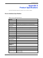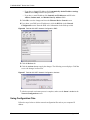
1
P-971M
Cable Modem
User’s Guide
Version 3.70.01
6/2005
Prestige 971M User’s Guide
2
P-971M User’s Guide
Copyright
Copyright © 2005 by ZyXEL Communications Corporation.
The contents of this publication may not be reproduced in any part or as a whole, transcribed,
stored in a retrieval system, translated into any language, or transmitted in any form or by any
means, electronic, mechanical, magnetic, optical, chemical, photocopying, manual, or
otherwise, without the prior written permission of ZyXEL Communications Corporation.
Published by ZyXEL Communications Corporation. All rights reserved.
Disclaimer
ZyXEL does not assume any liability arising out of the application or use of any products, or
software described herein. Neither does it convey any license under its patent rights nor the
patent rights of others. ZyXEL further reserves the right to make changes in any products
described herein without notice. This publication is subject to change without notice.
Trademarks
Trademarks mentioned in this publication are used for identification purposes only and may be
properties of their respective owners.
Copyright
2
P-971M User’s Guide
Federal Communications
Commission (FCC) Interference
Statement
This device complies with Part 15 of FCC rules. Operation is subject to the following two
conditions:
• This device may not cause harmful interference.
• This device must accept any interference received, including interference that may cause
undesired operations.
This equipment has been tested and found to comply with the limits for a Class B digital
device pursuant to Part 15 of the FCC Rules. These limits are designed to provide reasonable
protection against harmful interference in a commercial environment. This equipment
generates, uses, and can radiate radio frequency energy, and if not installed and used in
accordance with the instructions, may cause harmful interference to radio communications.
If this equipment does cause harmful interference to radio/television reception, which can be
determined by turning the equipment off and on, the user is encouraged to try to correct the
interference by one or more of the following measures:
• Reorient or relocate the receiving antenna.
• Increase the separation between the equipment and the receiver.
• Connect the equipment into an outlet on a circuit different from that to which the receiver
is connected.
• Consult the dealer or an experienced radio/TV technician for help.
Notice 1
Changes or modifications not expressly approved by the party responsible for compliance
could void the user's authority to operate the equipment.
Information for Canadian Users
This Class B digital apparatus complies with Canadian ICES-003.
Cet appareil numerique de la classe B est conforme a la norme NMB-003 du Canada.
Certifications
Go to www.zyxel.com
3
Federal Communications Commission (FCC) Interference Statement
P-971M User’s Guide
1 Select your product from the drop-down list box on the ZyXEL home page to go to that
product's page.
2 Select the certification you wish to view from this page.
Federal Communications Commission (FCC) Interference Statement
4
P-971M User’s Guide
Safety Warnings
For your safety, be sure to read and follow all warning notices and instructions.
• To reduce the risk of fire, use only No. 26 AWG (American Wire Gauge) or larger
telecommunication line cord.
• Do NOT open the device or unit. Opening or removing covers can expose you to
dangerous high voltage points or other risks. ONLY qualified service personnel can
service the device. Please contact your vendor for further information.
• Use ONLY the dedicated power supply for your device. Connect the power cord or
power adaptor to the right supply voltage (110V AC in North America or 230V AC in
Europe).
• Do NOT use the device if the power supply is damaged as it might cause electrocution.
• If the power supply is damaged, remove it from the power outlet.
• Do NOT attempt to repair the power supply. Contact your local vendor to order a new
power supply.
• Place connecting cables carefully so that no one will step on them or stumble over them.
Do NOT allow anything to rest on the power cord and do NOT locate the product where
anyone can walk on the power cord.
• If you wall mount your device, make sure that no electrical, gas or water pipes will be
damaged.
• Do NOT install nor use your device during a thunderstorm. There may be a remote risk of
electric shock from lightning.
• Do NOT expose your device to dampness, dust or corrosive liquids.
• Do NOT use this product near water, for example, in a wet basement or near a swimming
pool.
• Make sure to connect the cables to the correct ports.
• Do NOT obstruct the device ventilation slots, as insufficient airflow may harm your
device.
• Do NOT store things on the device.
• Connect ONLY suitable accessories to the device.
5
Safety Warnings
P-971M User’s Guide
ZyXEL Limited Warranty
ZyXEL warrants to the original end user (purchaser) that this product is free from any defects
in materials or workmanship for a period of up to two years from the date of purchase. During
the warranty period, and upon proof of purchase, should the product have indications of failure
due to faulty workmanship and/or materials, ZyXEL will, at its discretion, repair or replace the
defective products or components without charge for either parts or labor, and to whatever
extent it shall deem necessary to restore the product or components to proper operating
condition. Any replacement will consist of a new or re-manufactured functionally equivalent
product of equal value, and will be solely at the discretion of ZyXEL. This warranty shall not
apply if the product is modified, misused, tampered with, damaged by an act of God, or
subjected to abnormal working conditions.
Note
Repair or replacement, as provided under this warranty, is the exclusive remedy of the
purchaser. This warranty is in lieu of all other warranties, express or implied, including any
implied warranty of merchantability or fitness for a particular use or purpose. ZyXEL shall in
no event be held liable for indirect or consequential damages of any kind of character to the
purchaser.
To obtain the services of this warranty, contact ZyXEL's Service Center for your Return
Material Authorization number (RMA). Products must be returned Postage Prepaid. It is
recommended that the unit be insured when shipped. Any returned products without proof of
purchase or those with an out-dated warranty will be repaired or replaced (at the discretion of
ZyXEL) and the customer will be billed for parts and labor. All repaired or replaced products
will be shipped by ZyXEL to the corresponding return address, Postage Paid. This warranty
gives you specific legal rights, and you may also have other rights that vary from country to
country.
ZyXEL Limited Warranty
6
P-971M User’s Guide
Customer Support
Please have the following information ready when you contact customer support.
•
•
•
•
Product model and serial number.
Warranty Information.
Date that you received your device.
Brief description of the problem and the steps you took to solve it.
TELEPHONEA
WEB SITE
SALES E-MAIL
FAX
FTP SITE
[email protected]
+886-3-578-3942
[email protected]
+886-3-578-2439
www.zyxel.com
ZyXEL Communications Corp.
www.europe.zyxel.com 6 Innovation Road II
Science Park
Hsinchu 300
ftp.zyxel.com
Taiwan
ftp.europe.zyxel.com
[email protected]
+420 241 091 350
[email protected]
+420 241 091 359
[email protected]
+45 39 55 07 00
[email protected]
+45 39 55 07 07
[email protected]
+358-9-4780-8411
[email protected]
+358-9-4780 8448
[email protected]
+33 (0)4 72 52 97 97
METHOD SUPPORT E-MAIL
REGULAR MAIL
LOCATION
CORPORATE
HEADQUARTERS
(WORLDWIDE)
CZECH REPUBLIC
DENMARK
FINLAND
SPAIN
SWEDEN
7
www.zyxel.dk
ZyXEL Communications A/S
Columbusvej 5
2860 Soeborg
Denmark
www.zyxel.fi
ZyXEL Communications Oy
Malminkaari 10
00700 Helsinki
Finland
www.zyxel.fr
ZyXEL France
1 rue des Vergers
Bat. 1 / C
69760 Limonest
France
www.zyxel.de
ZyXEL Deutschland GmbH.
Adenauerstr. 20/A2 D-52146
Wuerselen
Germany
ZyXEL Communications Inc.
1130 N. Miller St.
Anaheim
CA 92806-2001
U.S.A.
[email protected]
+49-2405-6909-0
[email protected]
+49-2405-6909-99
[email protected]
+1-800-255-4101
+1-714-632-0882
www.us.zyxel.com
[email protected]
+1-714-632-0858
ftp.us.zyxel.com
[email protected]
+47 22 80 61 80
www.zyxel.no
[email protected]
+47 22 80 61 81
ZyXEL Communications A/S
Nils Hansens vei 13
0667 Oslo
Norway
[email protected]
+34 902 195 420
www.zyxel.es
[email protected]
+34 913 005 345
ZyXEL Communications
Alejandro Villegas 33
1º, 28043 Madrid
Spain
[email protected]
+46 31 744 7700
www.zyxel.se
[email protected]
+46 31 744 7701
ZyXEL Communications A/S
Sjöporten 4, 41764 Göteborg
Sweden
NORTH AMERICA
NORWAY
ZyXEL Communications
Czech s.r.o.
Modranská 621
143 01 Praha 4 - Modrany
Ceská Republika
+33 (0)4 72 52 19 20
FRANCE
GERMANY
www.zyxel.cz
Customer Support
P-971M User’s Guide
TELEPHONEA
WEB SITE
SALES E-MAIL
FAX
FTP SITE
[email protected]
+44 (0) 1344 303044
08707 555779 (UK only)
www.zyxel.co.uk
[email protected]
+44 (0) 1344 303034
ftp.zyxel.co.uk
METHOD SUPPORT E-MAIL
REGULAR MAIL
LOCATION
UNITED KINGDOM
ZyXEL Communications UK
Ltd.,11, The Courtyard,
Eastern Road, Bracknell,
Berkshire, RG12 2XB,
United Kingdom (UK)
a. “+” is the (prefix) number you enter to make an international telephone call.
Customer Support
8
P-971M User’s Guide
9
Customer Support
Prestige 971M User’s Guide
Table of Contents
Copyright .................................................................................................................. 2
Federal Communications Commission (FCC) Interference Statement ............... 3
Safety Warnings ....................................................................................................... 5
ZyXEL Limited Warranty.......................................................................................... 6
Customer Support.................................................................................................... 7
Table of Contents ................................................................................................... 10
List of Figures ........................................................................................................ 14
List of Tables .......................................................................................................... 16
Preface .................................................................................................................... 18
Chapter 1
Getting To Know Your Prestige............................................................................. 20
1.1 Introducing the Prestige .....................................................................................20
1.1.1 Features of the Prestige ...........................................................................20
1.2 Accessing the Web Configurator ........................................................................21
Chapter 2
Connection Screen. ............................................................................................... 24
2.1 Connection Screen Overview .............................................................................24
2.1.1 Acquire Downstream Channel ..................................................................25
2.1.2 Connectivity State .....................................................................................25
2.1.3 Boot State .................................................................................................26
2.1.4 Configuration File ......................................................................................26
2.1.5 Security .....................................................................................................27
2.1.6 Channels ...................................................................................................27
Chapter 3
Software Screen ..................................................................................................... 30
3.1 Introduction ........................................................................................................30
Chapter 4
SNMP Event Log .................................................................................................... 32
4.1 Introduction ........................................................................................................32
Table of Contents
10
Prestige 971M User’s Guide
Chapter 5
Introduction to CLI ................................................................................................. 40
5.1 Command Line Interface Overview ....................................................................40
5.1.1 Accessing the Command Line Interface ...................................................40
5.1.2 Command Syntax Conventions ................................................................41
5.2 Getting Help .......................................................................................................42
5.2.1 The Manual Command .............................................................................43
5.3 Using Command History ....................................................................................44
5.3.1 Executing History Commands Using ! ......................................................45
5.3.2 The Image File ..........................................................................................47
5.4 Saving Your Configuration ..................................................................................47
5.5 Logging Out ........................................................................................................48
5.6 Command Summary ..........................................................................................48
5.6.1 General Commands ..................................................................................48
5.6.2 CM Commands .........................................................................................50
5.6.3 docsis_clt Commands ...............................................................................51
Chapter 6
Command Examples .............................................................................................. 52
6.1 General Command Examples ............................................................................52
6.1.1 syntax .......................................................................................................52
6.1.2 usage ........................................................................................................53
6.1.3 version ......................................................................................................53
6.1.4 system time ...............................................................................................54
6.1.5 save ..........................................................................................................55
6.1.6 logout ........................................................................................................55
6.2 CM Command Examples ...................................................................................55
6.2.1 load_config ...............................................................................................55
6.2.2 run_app .....................................................................................................56
6.2.3 ping ...........................................................................................................56
6.2.4 telnet_pass ...............................................................................................57
6.2.5 web_admin_password ..............................................................................58
6.3 docsis_clt Command Examples .........................................................................58
6.3.1 copy_image ..............................................................................................58
6.3.2 dload .........................................................................................................59
6.3.3 goto_ds .....................................................................................................60
6.3.4 scan_stop .................................................................................................60
Appendix A
Product Specifications ......................................................................................... 62
Device Hardware Specification ................................................................................ 62
Sample Cable Modem Configuration File. ............................................................... 64
11
Table of Contents
Prestige 971M User’s Guide
Appendix B
Setting up Your Computer’s IP Address.............................................................. 66
Windows 95/98/Me................................................................................................... 66
Installing Components ....................................................................................... 67
Configuring ........................................................................................................ 68
Verifying Settings ............................................................................................... 69
Windows 2000/NT/XP .............................................................................................. 69
Verifying Settings ............................................................................................... 74
Macintosh OS 8/9..................................................................................................... 74
Verifying Settings ............................................................................................... 76
Macintosh OS X ....................................................................................................... 76
Verifying Settings ............................................................................................... 77
Linux......................................................................................................................... 77
Using the K Desktop Environment (KDE) .......................................................... 78
Using Configuration Files................................................................................... 79
Figure 51 Verifying Settings ...............................................................................81
Index........................................................................................................................ 82
Table of Contents
12
Prestige 971M User’s Guide
13
Table of Contents
Prestige 971M User’s Guide
List of Figures
Figure 1 Web browser URL screen. .................................................................................... 21
Figure 2 Web Configurator login screen. ............................................................................ 21
Figure 3 Connection Screen.. ............................................................................................. 22
Figure 4 Password security screen. ................................................................................... 23
Figure 5 Connection Status Screen .................................................................................... 25
Figure 6 Software Status Screen ........................................................................................ 30
Figure 7 Event Log Screen ................................................................................................. 33
Figure 8 CLI: Login Screen ................................................................................................ 41
Figure 9 CLI: Getting Help Example 1 ............................................................................... 42
Figure 10 CLI: Getting Help Example 2 ............................................................................. 43
Figure 11 CLI: Getting Help Example 3 .............................................................................. 44
Figure 12 CLI: History Command Example ........................................................................ 45
Figure 13 ! Command Example 1 ...................................................................................... 46
Figure 14 ! Command Example 2 ...................................................................................... 47
Figure 15 CLI: Save Command Example .......................................................................... 48
Figure 16 CLI: Logout Command Example ........................................................................ 48
Figure 17 syntax Command Example ................................................................................ 52
Figure 18 usage Command Example ................................................................................. 53
Figure 19 system_time Command Example ...................................................................... 54
Figure 20 save Command Example ................................................................................... 55
Figure 21 load_config Command Example ........................................................................ 56
Figure 22 run_app Command Example ............................................................................. 56
Figure 23 ping Command Example .................................................................................... 57
Figure 24 telnet_pass Command Example ........................................................................ 57
Figure 25 web_admin_password Command Example ....................................................... 58
Figure 26 copy_image Command Example ....................................................................... 59
Figure 27 dload Command Example .................................................................................. 59
Figure 28 goto_ds Command Example .............................................................................. 60
Figure 29 scan_stop Command Example .......................................................................... 60
Figure 30 WIndows 95/98/Me: Network: Configuration ....................................................... 67
Figure 31 Windows 95/98/Me: TCP/IP Properties: IP Address ........................................... 68
Figure 32 Windows 95/98/Me: TCP/IP Properties: DNS Configuration .............................. 69
Figure 33 Windows XP: Start Menu .................................................................................... 70
Figure 34 Windows XP: Control Panel ................................................................................ 70
Figure 35 Windows XP: Control Panel: Network Connections: Properties ......................... 71
Figure 36 Windows XP: Local Area Connection Properties ................................................ 71
Figure 37 Windows XP: Internet Protocol (TCP/IP) Properties ........................................... 72
Figure 38 Windows XP: Advanced TCP/IP Properties ........................................................ 73
List of Figures
14
Prestige 971M User’s Guide
Figure 39 Windows XP: Internet Protocol (TCP/IP) Properties ........................................... 74
Figure 40 Macintosh OS 8/9: Apple Menu .......................................................................... 75
Figure 41 Macintosh OS 8/9: TCP/IP .................................................................................. 75
Figure 42 Macintosh OS X: Apple Menu ............................................................................. 76
Figure 43 Macintosh OS X: Network ................................................................................... 77
Figure 44 Red Hat 9.0: KDE: Network Configuration: Devices .......................................... 78
Figure 45 Red Hat 9.0: KDE: Ethernet Device: General ................................................... 78
Figure 46 Red Hat 9.0: KDE: Network Configuration: DNS ............................................... 79
Figure 47 Red Hat 9.0: KDE: Network Configuration: Activate ......................................... 79
Figure 48 Red Hat 9.0: Dynamic IP Address Setting in ifconfig-eth0 ................................ 80
Figure 49 Red Hat 9.0: Static IP Address Setting in ifconfig-eth0
Figure 50 Red Hat 9.0: DNS Settings in resolv.conf
.................................... 80
........................................................ 80
Figure 51 Red Hat 9.0: Restart Ethernet Card .................................................................. 81
Figure 52 Red Hat 9.0: Checking TCP/IP Properties ........................................................ 81
15
List of Figures
Prestige 971M User’s Guide
List of Tables
Table 1 Connection Screen Summary ................................................................................ 27
Table 2 Software Status Screen ......................................................................................... 30
Table 3 Error Message Severity Levels - Priority Field. ..................................................... 33
Table 4 General Command Summary ................................................................................ 48
Table 5 CM Command Summary ....................................................................................... 50
Table 6 docsis_clt Command Summary ............................................................................. 51
Table 7 version Command Example
................................................................................. 54
Table 8 Device Hardware Specifications ............................................................................ 62
Table 9 Cable Modem Configuration file ............................................................................ 64
List of Tables
16
Prestige 971M User’s Guide
17
List of Tables
P-971M User’s Guide
Preface
Congratulations on your purchase of the Prestige 971M (P-971M) Cable Modem.
Note: Register your product online to receive e-mail notices of firmware upgrades and
information at www.zyxel.com for global products, or at www.us.zyxel.com for
North American products.
About This User's Guide
This manual is designed to guide you through the configuration of your Prestige for its various
applications.
Syntax Conventions
• “Enter” means for you to type one or more characters. “Select” or “Choose” means for
you to use one predefined choices.
• The SMT menu titles and labels are in Bold Times New Roman font. Predefined field
choices are in Bold Arial font. Command and arrow keys are enclosed in square
brackets. [ENTER] means the Enter, or carriage return key; [ESC] means the Escape key
and [SPACE BAR] means the Space Bar.
• Mouse action sequences are denoted using a comma. For example, “click Start, (All)
Programs, Accessories and then Command Prompt” means first click Start, then point
your mouse pointer to Programs, point your mouse pointer to Accessories and then click
Command Prompt.
• For brevity’s sake, we will use “e.g.,” as a shorthand for “for instance”, and “i.e.,” for
“that is” or “in other words” throughout this manual.
• The Prestige 971M may be referred to as simply the “Prestige” in this User’s guide.
Related Documentation
• Supporting Disk
Refer to the included CD for support documents.
• Quick Start Guide
The Quick Start Guide is designed to help you get up and running right away. They
contain connection information and instructions on getting started.
• ZyXEL Glossary and Web Site
Please refer to www.zyxel.com for an online glossary of networking terms and additional
support documentation.
Preface
18
P-971M User’s Guide
User Guide Feedback
Help us help you. E-mail all User Guide-related comments, questions or suggestions for
improvement to [email protected] or send regular mail to The Technical Writing
Team, ZyXEL Communications Corp., 6 Innovation Road II, Science-Based Industrial Park,
Hsinchu, 300, Taiwan. Thank you.
19
Preface
P-971M User’s Guide
CHAPTER 1
Getting To Know Your Prestige
This chapter describes the key features and applications of your Prestige 971M (P-971M). For
front panel LED indicator information and rear panel connections, including power
connections, please refer to the Quick Start Guide.
1.1 Introducing the Prestige
Your P-971M provides fast video and data communication with a cable operator and the
internet. Its 10/100M auto-negotiating LAN interface enables fast data transfer between
devices connected to your network. The web browser-based Graphical User Interface (GUI)
provides for easy management and remote status monitoring over the cable network.
Note: The standard your cable operator supports determines the maximum upstream
and downstream speeds attainable. Actual speeds attained depend on the
distance from the cable operator’s central office, noise, etc.
1.1.1 Features of the Prestige
The following sections describe the features of the Prestige.
Note: See the product specifications in the appendix for detailed features and
standards supported.
Built-in Ethernet Port
The 10/100 Mbps auto-negotiating Ethernet port allows the Prestige to detect the speed of
incoming transmissions and adjust appropriately without manual intervention. It allows data
transfer of either 10 Mbps or 100 Mbps in either half-duplex or full-duplex mode depending
on your Ethernet network. The port is also auto-crossover (MDI/MDI-X) meaning it
automatically adjusts to either a crossover or straight-through Ethernet cable.
High Speed Internet Access
The Prestige supports transmission speeds of up to 30 Mbps upstream and 30 Mbps
downstream. Actual speeds attained depend on your ISP and cable operator’s CMTS
environment.
Chapter 1 Getting To Know Your Prestige
20
P-971M User’s Guide
DHCP
DHCP (Dynamic Host Configuration Protocol) allows the individual clients (computers)
to obtain the TCP/IP configuration at start-up from a centralized DHCP server. The
Prestige supports this capability by default. The Prestige acts as a surrogate DHCP server
(DHCP Relay) where it relays IP address assignments from the actual real DHCP server
to the clients.
Security and Remote Monitoring Support
Two types of system security are provided by your Prestige: Webadmin and User. Your
Prestige also supports remote monitoring using SNMP.
1.2 Accessing the Web Configurator
The P-971M supports two types of web configurator logins which correspond to the two user
names available from the Web Configurator: webadmin and user. Webadmin allows viewing
of all the status screens, while user allows viewing of all status screens viewing except the
Event Log screen.
1 Launch your web browser. Enter “192.168.100.1” as the web site address. The subnet
mask is 255.255.255.0. If you do not see the next screen, please read the
Troubleshooting section of the Quick Start Guide.
Figure 1 Web browser URL screen.
2 An Enter Network Password window displays on your browser. Enter the user name
(webadmin or user), password (“1234” is the default password for both user names) and
click OK.
Note: Change your login information in the Security section of the web configurator
Figure 2 Web Configurator login screen.
21
Chapter 1 Getting To Know Your Prestige
P-971M User’s Guide
You should see the connection screen after a successful login. If you do not see this screen
please refer to the Troubleshooting section of the Quick Start Guide. Click on the Security
link to change the P-971M password or to restore the factory default password if needed.
Please click on Security to change your P-971M password now.
Figure 3 Connection Screen..
In the Password Change User ID box enter your username. In the New Password box enter
your new password. In the Re-Enter New Password box enter your new password again.
Finish by entering your old password in the Current User ID Password box. Passwords may
be up to 16 characters in length and must be alphanumeric (a-zA-Z0-9), no other characters are
allowed.
Note: If you click Yes on Restore Factory Defaults the P-971M will disregard any
password changes you have entered. Only do this when you want to reset your
Prestige to its factory default settings.
Chapter 1 Getting To Know Your Prestige
22
P-971M User’s Guide
Figure 4 Password security screen.
23
Chapter 1 Getting To Know Your Prestige
P-971M User’s Guide
CHAPTER 2
Connection Screen.
This chapter describes important system information presented on the connection status
screen. This information is useful for debugging the connection between your P-971M and the
cable operator. The DOCSIS 2.0 specification may be needed as aid for clarification.
2.1 Connection Screen Overview
After logging in to your P-971M you will see the connection screen. The connection screen
shows the results of the hardware negotiation between the P-971M and your CMTS.
As shown in figure Figure 5 on page 25, the connection screen presents information in four
sections: Procedure, Downstream Channel Upstream Channel, and CM IP Address. The
fields in each section are summarized in table Table 1 on page 27. All of the information in the
connection screen is read-only and/or calculated after the successful download of the
configuration file, and the negotiation of upstream/downstream channel parameters with the
cable operator’s CMTS.
Chapter 2 Connection Screen.
24
P-971M User’s Guide
Figure 5 Connection Status Screen
2.1.1 Acquire Downstream Channel
The P-971M must lock on to a cable operator’s offered channel to operate successfully. After
downloading the configuration file and checking its contents, your cable modem will attempt
to lock on to the offered channel. If successful, your cable modem has Locked on to the
channel; otherwise it is In Progress.
2.1.2 Connectivity State
The connectivity state is the current status of the connection between the cable modem and
your cable operator. During the initial negotiation with your cable operator’s CMTS, the P971M must establish a clear upstream and downstream channel, which it accomplishes in a
series of well defined steps. If the configuration file download, installation, DHCP, timer
settings, and communication channel negotiation succeeded, your cable modem is OK and
Operational; otherwise it is In Progress and one of the seven messages described in the
paragraphs below.
You will see Not Synchronized if the P-971M did not detect synchronization for QAM signal
timing, synchronization for FEC framing, synchronization for MPEG packets, or recognize
synchronization of downstream channel MAC address.
You will see Upstream Parameters Acquired if the P-971M is waiting for an upstream
channel message from your cable operator’s CMTS.
You will see Ranging Complete if the P-971M has successfully adjusted local channel
parameters (downstream power/frequency, upstream power/frequency, channel ID) and all
values are within specified ranges.
25
Chapter 2 Connection Screen.
P-971M User’s Guide
You will see IP Complete if your P-971M has successfully negotiated a DHCP connection
with the CMTS and set your IP address.
You will see TOD Established (Time Of Day) if your cable operator’s time server has
communicated with the P-971M to establish the current time and date used for event logging.
You will see Security Established if baseline privacy was requested in the configuration file
and initialized by the P-971M.
You will see Registration Complete if your P-971M has received authorization from the
CMTS to forward internet packets. Authorization must first be requested in the configuration
file.
2.1.3 Boot State
When downloading the configuration file and booting, your P-971M passes through several
negotiation stages with the CMTS. All communication steps: TFTP, DHCP Offer/Response,
and Time Server must complete in order for the configuration to be successful. TFTP is the
download protocol used to install the configuration file.
If there is a problem making a TFTP connection with your CMTS, you will see the message
Waiting for TFTP. If the P-971M does not receive a DHCP offer from the CMTS you will
see the message Waiting for DHCP Offer. Once the P-971M has responded to the DHCP
offer it again waits for a response from the CMTS, if it does not receive a response you will
see the message Waiting for DHCP Response. If the cable operator’s time server does not
respond your will see the message Waiting for Timer Server. If the download and
installation of the configuration file succeeds you will see the message Operational.
Your cable modem must receive an offer of a DHCP IP Address from the CMTS and respond
to that offer in order to set your IP Address. First your cable modem is Waiting for DHCP
Offer, if the offer is received by your cable modem it responds Waiting for DHCP Response
to the CMTS. Once a response is received your IP Address is set and can be viewed under the
CM IP Address section of this screen or in the Software status screen. Note that the DHCP IP
Address setting must be completed successfully in order for your cable modem to download
the configuration file.
2.1.4 Configuration File
This is the name of the cable modem configuration file downloaded from your cable
operator’s CMTS using the TFTP protocol. This is a binary format file which must be
DOCSIS 2.0 compliant (see RFC 2132 for additional information) A sample configuration file
is included in the appendix.
Chapter 2 Connection Screen.
26
P-971M User’s Guide
2.1.5 Security
Your cable modem has features built-in to run Baseline Privacy (BP). BP is used as a privacy
mechanism to protect user data flowing across the cable network and to prevent unauthorized
access to the CMTS data flowing across the network. BP also supports access control lists
(ACLs), filtering, tunnels, spoof protection, and source IP filtering on the RF subnets to
prevent users from using IP addresses that are invalid. BP security information must be
included in your cable operator’s configuration file to enable security. If your cable operator
did not supply this information in the configuration file BP security is Disabled. Further
information can be found in DOCSIS 2.0.
2.1.6 Channels
Your P-971M uses different communications methods if it is receiving information from the
cable operator, or if it is sending information to the cable operator. These are called the
Downstream Channel and Upstream Channel respectively. The channel numbers and
frequencies are advertised by the CMTS during the initial booting of the P-971M; these may
also be set in the configuration file.
Table 1 Connection Screen Summary
LABEL
DESCRIPTION
Acquire
Downstream
Channel
The P-971M has Locked onto the downstream channel. The status message will
display the frequency in hertz.
The channel lock is In Progress. The status message will display the frequency in
hertz.
Connectivity
State
The P-971M is Operational and the status is OK.
The P-971M connectivity is In Progress. See the description for Connectivity State.
Boot State
The boot state of the P-971M is Operational.
The boot state of the P-971M is In Progress. See the description for Boot State.
Configuration File A configuration file (cmb.cfg) was successfully downloaded from the upstream cable
operator’s CMTS, and installed on your P-971M. The status message displays OK.
The P-971M is attempting to negotiate and download a configuration file from your
cable operator’s CMTS. The status message displays In Progress.
27
Security
Baseline privacy security is enabled and the status message displays Enabled. The
comment field displays BPI.
The baseline privacy security is Disabled and the status message displays
Disabled.
Downstream
Channel
This is the data path used by the CMTS for sending information to your P-971M.
Lock Status
The P-971M is either Locked or Not Locked on to the channel advertised by your
cable operator’s CMTS.
Channel ID
A standard channel number from the DOCSIS 2.0 specification. Channel numbers
and channel frequencies are specified in pairs in DOCSIS 2.0.
Downstream
Frequency
A standard channel frequency (in hertz) from the DOCSIS 2.0 specification.
SNR
The Signal to Noise Ratio (in decibels/mili-volt), the ratio of signal power to channel
noise power. This value is set by the CMTS.
Chapter 2 Connection Screen.
P-971M User’s Guide
Table 1 Connection Screen Summary (continued)
LABEL
DESCRIPTION
Modulation
This is the method used to encode transmission information, similar to FM or AM on
your radio. The P-971M supports QAM256 or QAM64 (Quadrature Amplitude
Modulation) for the downstream channel.
Symbol Rate
The symbol rate (in Kilo symbols/second) for communication from the CMTS to the
P-971M. This is set during initial configuration with a value supplied by the CMTS.
Typical values for QAM64 are 5.05 Mega-symbols/second, and for QAM256 5.36
Mega-symbols/second.
Downstream
Power
The power level (in decibels/mili-volt). This value is set by the CMTS.
Upstream
Channel
This is the data path used by the P-971M for sending information to your CMTS.
Lock Status
The P-971M is either Locked or Not Locked on to the channel advertised by your
cable operator’s CMTS.
Channel ID
A standard channel number from the DOCSIS 2.0 specification. Channel numbers
and channel frequencies are specified in pairs in DOCSIS 2.0.
Upstream
Frequency
A standard channel frequency (in hertz) from the DOCSIS 2.0 specification.
Modulation
This is the method used to encode transmission information, similar to FM or AM on
your radio. The P-971M supports QAM16 or QPSK (Quadrature Phase Shift
Keying) for the upstream channel.
Symbol Rate
The symbol rate (in Kilo-symbols/second) for communication from the P-971M to the
CMTS. This is set during initial configuration with a value supplied by the CMTS.
Upstream
Power
The power level (in decibels/mili-volt). This value is set by the CMTS.
CM IP Address
This is the IP address negotiated with your cable operator, after a successful
download of the modem configuration file and DHCP negotiation (e.g.10.21.0.11).
This field may also be blanked out with a series of dashed lines (--- --- --- ---)
indicating that the modem configuration failed or is in progress; no IP address has
been set.
Duration
The IP address negotiated with your cable operator has a default lifetime of 7 days
(e.g. D: 00 H: 01 M: 00 S: 00). The sequence (D -- H -- M -- S --) indicates that your
modem configuration has failed or is in progress; no IP address duration has been
set.
Expires
This is the expiration date of the IP address, after installation of the modem
configuration file and DHCP negotiation. The default is 7 days (e.g. Wed Jul 02
00:26:23 2005). A sequence of dashes (--- --- -- -- -- -- ----) indicates that your
modem configuration has failed or is in progress; no IP address expiry date has
been set.
Current System
Time
This is the current date and time, and is set by your cable operator’s time server.
Chapter 2 Connection Screen.
28
P-971M User’s Guide
29
Chapter 2 Connection Screen.
P-971M User’s Guide
CHAPTER 3
Software Screen
3.1 Introduction
The Software status screen shows you information about your cable modem software and the
results of the configuration file TFTP download, installation, and channel negotiation with the
CMTS. Please refer to figure Figure 6 on page 30.
Figure 6 Software Status Screen
This screen is divided into sections: an Information section and a Status section. The
Information section displays parameters read directly from your cable modem software (with
the exception of CM certificate) while the Status section displays parameters read after a
successful configuration of your cable modem. The software status screen messages are
summarized in Table 2 on page 30.
Table 2 Software Status Screen
LABEL
DESCRIPTION
Standard Specification Compliant
This is the relevant technical standard that your cable modem
abides by, currently DOCSIS 2.0. This value is read from the
internal cable modem software and may change with future
software updates.
Hardware Version
This is the version of your cable modem hardware. This value is
read from the internal cable modem software.
Chapter 3 Software Screen
30
P-971M User’s Guide
Table 2 Software Status Screen (continued)
31
LABEL
DESCRIPTION
Software Version
This is the version of the internal software installed and running
on your P-971M. This value is read from the internal cable modem
software.
Cable Modem MAC Address
This is the RF MAC address of your cable modem. This value is
read from the internal cable modem software.
Cable Modem Serial Number
This is the serial number of your cable modem from the underside
panel Bar Code label. This value is read from the internal cable
modem software.
CM Certificate
The CM Certificates provide a secure method for uploading cable
modem public key information to your cable operator as specified
in DOCSIS 2.0. This is a form of digital certificate that is unique for
each hardware vendor. It contains an encoded public key and
digital signature and must be present in the cable modem
configuration file downloaded from the cable operator. If installed
this field will display Installed, if not this field will display Not
Installed.
System Up Time
This is the time since your cable modem has successfully
downloaded/installed a configuration file and negotiated channel
parameters with the cable operator. This value is read from the
cable operator's network time server. If the timer server was not
accessible this field is grayed out.
Network Access
This field displays whether your cable modem is allowed to
forward packets from its LAN port to the cable operator and on to
the internet. This value is read from the configuration file. Network
access is either Allowed or Denied depending upon your
configuration file setting.
Cable Modem IP Address
After a successful configuration of your cable modem the IP
Address will be set with a value provided by your cable operator. If
no IP Address is set network devices connected to the LAN port
cannot connect to the internet. If your IP Address is not set this
field displays as a series of dashed lines.
Chapter 3 Software Screen
P-971M User’s Guide
CHAPTER 4
SNMP Event Log
4.1 Introduction
The SNMP Event Log Screen shows you information about each step of your cable modem's
configuration file download, installation, and channel negotiation with the CMTS. This
information is extremely useful for debugging purposes when attempting to troubleshoot a
connection problem between your P-971M and the cable operator’s CMTS. Please refer to
figure Figure 7 on page 33 for an abbreviated event log.
Chapter 4 SNMP Event Log
32
P-971M User’s Guide
Figure 7 Event Log Screen
This screen consists of a list of Simple Network Management Protocol (SNMP) messages
which display the results of the configuration file download and installation on your P-971M
as well as negotiation status information between the CMTS and your P-971M. Each step in
the initial configuration as noted in Chapter 2 on page 24 may pass or fail. Warning or error
messages are shown in the event log for easy troubleshooting.
The event log is presented as three fields: time the event occurred (actual time or Time Not
Established), Priority level of the error with number (Emergency, Alert, Critical, Error,
Warning, Notice, Informational, and Debug), and a short Description message of the error
itself. Please refer to table Table 3 on page 33 for a description of the Priority level error
messages.
Table 3 Error Message Severity Levels - Priority Field.
33
ERROR CLASS
LEVEL NUMBER
DESCRIPTION
Emergency
0
Your P-971M requires immediate attention. Any problems
may affect the remaining nodes on your network.
Alert
1
A system or connection failure has occurred. Immediate
attention is needed.
Chapter 4 SNMP Event Log
P-971M User’s Guide
Table 3 Error Message Severity Levels - Priority Field.
ERROR CLASS
LEVEL NUMBER
DESCRIPTION
Critical
2
Immediate attention is needed to avoid a system or
connection failure.
Error
3
Attention is needed to avoid possible future system or
connection failures.
Warning
4
System attention is needed in the near future. Failure to solve
this warning can lead to further system problems,
Notice
5
Normal status. System administrators take notice.
Informational
6
Informational message only. May or may not be significant.
Debug
7
System debugging is turned on.
What follows is a short explanation of the more common error and warning messages you are
likely to see in the Description field while debugging the connection between the P-971M and
the CMTS. Refer to DOCSIS 2.0 for additional information on SNMP status messages for
cable modems. Error and warning messages are shown in boldface type.
DHCP Warning - Non-critical field invalid in response (Critical).
The P-971M has received a response to its DHCP request from the cable operator’s CMTS,
but the responding DHCP server did not include all of the required fields in the message. This
message might also appear if one of the required fields in the DHCP message contains an
invalid value. Reconfigure the DHCP server so that it sends all of the required fields.
DHCP ERROR - The DHCP response does not contain all of the required
fields or the PS (Portal Services) is unable to determine provisioning mode.
The P-971M has received a response to its DHCP request from the cable operator’s CMTS,
but the responding DHCP server did not include all of the required fields in the message.
Please refer to appendix C of the DOCSIS 1.0 RF specification, appendix D of the DOCSIS
1.1 RF specification, appendix D of the DOCSIS 2.0 RF specification, and RFC 868 for
further information. Reconfigure the DHCP server so that it sends all of the required fields.
SYNC Timing Synchronization failure - Failed to acquire FEC framing
(Critical)
When attempting to lock on to the downstream channel your P-971M could not acquire
forward error correction (FEC) framing.
SYNC Timing Synchronization failure - Failed to acquire MAC framing
(Critical)
Your P-971M attempted to lock on to the downstream channel and was able to acquire
forward error correction (FEC) framing, but then failed to lock on to media access control
(MAC) framing. Note that this is not an ethernet MAC frametype.
Chapter 4 SNMP Event Log
34
P-971M User’s Guide
SYNC Timing Synchronization failure, Acquired FEC framing - Failed to
acquire MPEG2 Sync (Critical)
Your P-971M attempted to lock on to the downstream channel and was able to acquire
forward error correction (FEC) framing, but then failed to lock on to the MPEG2
synchronization signal.
SYNC Timing Synchronization failure - Failed to acquire QAM/QPSK symbol
timing (Critical)
Your P-971M could not lock on to the downstream channel’s quadrature amplitude
modulation/quadrature phase shift keying (QAM)/(QPSK) signal.
SYNC Timing Synchronization failure - Failed to receive MAC SYNC frame
within time-out period (Critical)
Your P-971M was able to acquire the media access control (MAC) framing initially, but
subsequently failed to receive the MAC SYNC frame within the specified timeout period.
Note that this is not an ethernet MAC frame type.
SW Upgrade Failed Before Download - Server not Present (Error)
You P-971M has made 16 unsuccessful attempts to download a new ZyXEL software image
from the TFTP server (CMTS or other TFTP server). After 16 attempts your cable modem
aborts the upgrade procedure. This error message might also occur if your cable modem has
received a fatal TFTP server error.
SW upgrade Failed after download - Incompatible SW file (Error)
An upgrade of your P-971M software failed because the downloaded image file was either the
wrong image, type, or was corrupted during file transfer.
UCD invalid or channel unusable (Critical)
The cable modem received an Upstream Channel Descriptor (UCD) message from the
CMTS, but it contains invalid information or specifies an upstream channel that is unusable.
A transmit opportunity was missed because the MAP arrived too late
(Information)
Your P-971M missed a transmit opportunity because the Bandwidth Allocation MAP (one slot
of the Time Division Multiplexing) signal arrived too late for your P-971M to use it.
DHCP FAILED - Discover sent, no offer received (Critical)
Your P-971M sent a DHCP discovery broadcast message to the cable operator’s CMTS, but
no DHCP server or DHCP relay agent replied with a DHCP offer response message.
35
Chapter 4 SNMP Event Log
P-971M User’s Guide
DHCP FAILED - Request sent, No response (Critical)
Your P-971M sent a DHCP discovery broadcast message to the cable operator’s CMTS, and
received a DHCP offer message in response from the cable operator, but when it sent a DHCP
request message to the indicated DHCP server, it did not receive a DHCP response message.
No UCD's Received - Timeout (Critical)
Your P-971M has not received any periodic Upstream Channel Descriptor (UCD) messages
from the CMTS within the specified timeout period.
Unicast Ranging Received Abort Response - Re- initializing MAC (Critical)
Your P-971M is online and has sent a periodic Ranging Request (RNG-REQ) message to the
CMTS, but it received an Abort Ranging reply instead. Your P-971M will reset its cable
interface and restart the registration process in response. Note that this is not an ethernet MAC
frame type.
SYNC Timing Synchronization failure - Loss of Sync (Critical)
Your P-971M had locked on to the downstream channel for a period of time, but then the
channel lock was lost and it was unable to be reacquired within five SYNC signal periods.
Your P-971M has reset its cable interface in response to this condition.
No Maintenance Broadcasts for Ranging opportunities received - T2 timeout (Critical)
Your P-971M did not receive a broadcast maintenance opportunity in which to transmit a
Ranging Request (RNG-REQ) within the required T2 timeout period (approximately 10
seconds). Your P-971M will reset its cable interface and restart the registration process.
Init RANGING Critical Ranging Request Retries exhausted (Critical)
Your P-971M has sent 16 Ranging Request (RNG-REQ) messages without
receiving a Ranging Response (RNG-RSP) reply message from your cable operator’s CMTS.
Your P-971M will reset its cable interface and restart the registration process. This error
message is typically caused by noise on the upstream channel that causes the loss of MAClayer messages. If your P-971M cannot raise its upstream channel transmit power to a level
that allows successful communication within the maximum timeout period, it resets its cable
interface and restarts the registration process.
Chapter 4 SNMP Event Log
36
P-971M User’s Guide
Received Response to Broadcast Maintenance Request, But no Unicast
Maintenance opportunities received - T4 timeout (Critical)
Your P-971M did not received a station maintenance opportunity in which to transmit a
Ranging Request (RNG-REQ) message within the required T4 timeout period (30 to 35
seconds). Your P-971M will reset its cable interface and restart the registration process.
Typically, this indicates an occasional, temporary loss of service, but if the problem persists,
check for possible service outages or maintenance activity on the part of your cable operator.
No Ranging Response received - T3 time-out (Critical)
Your P-971M sent a Ranging Request (RNG-REQ) message as part of its initial ranging
process, but did not receive a Ranging Response (RNG-RSP) message from the CMTS within
the required T3 timeout period. Your P-971M will adjust its upstream channel transmit power
and send another RNG-REQ message, up to the maximum of 16 successive attempts, or until
it reaches the maximum transmit power level.
Started Unicast Maintenance Ranging - No Response received - T3 time-out
(Critical)
Your P-971M is online and has sent a periodic Ranging Request (RNG-REQ) message to the
CMTS, without receiving a Ranging Response (RNG-RSP) message from the CMTS within
the required T3 timeout period. Your P-971M will send another RNG-REQ message, up to the
maximum of 16 successive attempts.
TFTP Failed - OUT OF ORDER packets (Critical)
Your P-971M attempted to download its DOCSIS compliant configuration file from the TFTP
server, but the download failed because the P-971M received at least one packet that was out
of order.
TFTP file complete - but failed Message Integrity check MIC (Critical)
Your P-971M successfully downloaded its configuration file, but the Message Integrity Check
(MIC) field sent with the configuration file does not match the one that your P-971M
generated internally after checking the file’s contents. This could indicate either that the
configuration file was corrupted during file transfer, or that the software tool that generated the
configuration file was not performing up to the DOCSIS standard. This message may also
indicate that a malicious user is attempting to download their own configuration file as part of
a theft-of-service attempt.
TFTP failed - request sent - No Response (Critical)
Your P-971M attempted to download the configuration file from the TFTP server specified by
the DHCP server, but the TFTP server has not replied.
TFTP failed - configuration file NOT FOUND (Critical)
37
Chapter 4 SNMP Event Log
P-971M User’s Guide
Your P-971M attempted to download its configuration file from the TFTP server specified by
the DHCP server, but the TFTP server replied that it could not find the requested file.
ToD request sent - No Response received (Warning)
Your P-971M sent a request to the time-of-day (ToD) server specified by the DHCP server,
but it did not receive a reply within the specified timeout period. Your P-971M defaults to
setting its onboard clock to midnight on January 1, 1970. Your P-971M can now proceed with
the registration process without receiving a ToD response, but will continue trying to contact
the ToD server every 5 minutes until it receives a valid response.
ToD Response received - Invalid data format (Warning)
Your P-971M received a reply from the ToD server that was specified by the DHCP server.
The reply from the ToD server was either an empty datagram or it contained invalid data (the
ToD server should send a reply that contains only one 32-bit number that indicates the number
of seconds since midnight on January 1, 1900). Please refer to RFC 868, Time Protocol for
additional information. The DOCSIS specifications do not allow the use of the Network Time
Protocol (NTP) or Simple Network Time Protocol (SNTP) ToD servers to set your P-971M’s
system time.
UCC- REQ received with invalid or out of range US channel ID (Error)
Your P-971M has received an Upstream Channel Change Request (UCC-REQ) message from
your cable operator’s CMTS that contains an upstream channel ID that is either invalid or out
of range.
UCC- REQ received unable to send UCC-RSP, no TX opportunity (Error)
Your P-971M has received an Upstream Channel Change Request (UCC-REQ) message from
your cable operator’s CMTS, but could not reply with an UCC Response message (UCC-RSP)
because it could not obtain a transmit timeslot.
US channel wide parameters not set before Burst Descriptors (Critical)
Your P-971M has received an Upstream Channel Descriptor (UCD) message from the CMTS,
but it did not set the channel and symbol rate parameters before beginning the set of TLVs
(Type Length Value) that specify the burst descriptors for the upstream channel. TLVs are an
encoding for three fields: the first field is the type of element, the second field is the length of
the element, and the third filed is the value of the element.
UCD & SYNC valid - NO MAPS for this channel (Critical)
Your P-971M has received valid Upstream Channel Descriptor (UCD) and SYNC messages
from the CMTS, but the upstream channel that is specified in the UCD does not offer your P971M any MAP (one slot of the Time Division Multiplexing) minislots in which to transmit.
Chapter 4 SNMP Event Log
38
P-971M User’s Guide
39
Chapter 4 SNMP Event Log
P-971M User’s Guide
CHAPTER 5
Introduction to CLI
This chapter introduces the line commands.
5.1 Command Line Interface Overview
In addition to the web configurator, you can use line commands to configure the Prestige. It is
recommended that you use the web configurator for everyday management of the Prestige and
that you use line commands for advanced Prestige diagnosis and troubleshooting. If you have
problems with your Prestige, customer support may request that you issue some of these
commands to assist them in troubleshooting.
5.1.1 Accessing the Command Line Interface
Note: Only one CLI management session is allowed at a time.
Use the following steps to telnet into your Prestige.
1 Connect your computer to the RJ-45 Ethernet port on the Prestige.
2 Make sure your computer IP address and the Prestige IP address are on the same subnet.
In Windows, click Start (usually in the bottom left corner), Run and then type telnet
192.168.100.1 (the default management IP address) and click OK.
3 A login screen displays. For your first login, enter the default administrator login
username “admin” and password “1234”.
4 After you have entered the username and password, press [ENTER] to display the command
prompt.
Chapter 5 Introduction to CLI
40
P-971M User’s Guide
Figure 8 CLI: Login Screen
ZyXEL Corporation Embedded Telnet Server (c) 2000-2003
WARNING:
Access allowed by authorized users only.
login: admin
password:
WARNING:
It is possible to crash the system, cause a deadlock,
or cause the connection to be shut down via Telnet.
Run commands with caution!
Console now switched to Telnet session...
CM>
5.1.2 Command Syntax Conventions
The system uses a one-level command structure. You must type the full command every time,
as follows.
CM> <command>
For instance, the following example displays the time (in milliseconds) since the Prestige was
last restarted.
CM> system_time
The conventions for typing in most CI commands are shown next.
command [(#)] [parms...]
• The command keywords are in courier new font.
• Commands are case-sensitive. Thus -i is not the same as -I.
• Commands can be abbreviated to the smallest unique string that differentiates the
command. For example the help command could be abbreviated to he.
• You may enter a unique part of a command and press [TAB] to have the Prestige
automatically display the full command. For example, if you enter he and press [TAB], the
full command of help automatically displays.
• The required fields in a command are enclosed in angle brackets <>.
• The range or length of the required field input is enclosed in curly brackets {}.
• The optional fields in a command are enclosed in square brackets [].
• The |symbol means or.
• Numbers are delimited by one of a space, comma, or semicolon (for example, 0,1;2 3).
A range is delimited by a dash (for example, 0-3). You can specify an open-ended range
that goes to the maximum allowed (for example, 3-). You can specify a range of values
using all delimiters (for example, 0 - 3,5,7-).
41
Chapter 5 Introduction to CLI
P-971M User’s Guide
For example,
web_user
[ID{20}] [password{20}]
means that you must specify the web configurator administrator username and password.
Note: Type all commands as displayed on the screen.
Use of undocumented commands or misconfiguration can damage the unit and
possibly render it unusable.
5.2 Getting Help
The CLI provides various commands to display detailed help information.
Type ?, help or man to display a list of valid commands or type a command followed by ?,
help or man to display a list of associated sub-commands.
Figure 9 CLI: Getting Help Example 1
CM> ?
Instance:
Console Thread (0x80fdc670)
!
?
find_command
help
man
pwd
usage
---load_config
logout
run_app
save
scan_show
telnet_pass
web_admin_password
---[docsis_ctl]
REM
history
sleep
ping
scan_band
telnet_user
web_user
cd
instances
syntax
reset
scan_set
version
dir
ls
system_time
restoreDefaults
scan_set_clear
web_admin_id
CM>
Chapter 5 Introduction to CLI
42
P-971M User’s Guide
Figure 10 CLI: Getting Help Example 2
CM> ping help
ERROR:
Addr
ss!
Invalid value for parameter IpAddress!
COMMAND:
USAGE:
'help' Must be a valid IP
ping
ping
IpAddress
DESCRIPTION:
Pings the specified target IP address, sending 3 64-byte packets, and
waiting
up to 5 seconds for a response. This is a basic 'standard' ping. For more
options or control over ping parameters and behavior.
In order for this to work, the CM must either have successfully completed
DHCP, or must otherwise have been configured with a valid IP address.
Note that this command causes the ping options to be reset to their default
state.
This may be disabled if the platform doesn't provide an implementation of
ping.
EXAMPLES:
ping 11.24.4.3
-- Ping IP address 11.24.4.3.
CM>
5.2.1 The Manual Command
In addition to the ? and help commands, you can use the man (manual) command to display
detailed command usage information. The following figure shows an example.
43
Chapter 5 Introduction to CLI
P-971M User’s Guide
Figure 11 CLI: Getting Help Example 3
CM> man ping
Instance:
COMMAND:
USAGE:
Console Thread (0x80fdc670)
ping
ping
IpAddress
DESCRIPTION:
Pings the specified target IP address, sending 3 64-byte packets, and
waiting
up to 5 seconds for a response. This is a basic 'standard' ping. For more
options or control over ping parameters and behavior.
In order for this to work, the CM must either have successfully completed
DHCP, or must otherwise have been configured with a valid IP address.
Note that this command causes the ping options to be reset to their default
state.
This may be disabled if the platform doesn't provide an implementation of
ping.
EXAMPLES:
ping 11.24.4.3
-- Ping IP address 11.24.4.3.
--------------------------------------------------------------------------CM>
5.3 Using Command History
The Prestige keeps a list of up to 16 commands you have entered for the current CLI session.
You can use any commands in the history again by pressing the up (y) or down (z) arrow key
to scroll through the previously used commands and press [ENTER]. Use the history
command to display the list of commands.
Note: The history command is not stored in the history command list.
Chapter 5 Introduction to CLI
44
P-971M User’s Guide
Figure 12 CLI: History Command Example
CM> history
Instance:
Console Thread (0x80fdc670)
Command History:
0)
1)
2)
3)
4)
5)
6)
7)
8)
9)
10)
11)
12)
13)
14)
15)
CM>
cd ..
cd d
dir
ls
dsdiag
ugdiag
usage
exit
cd ..
dir he
dir dir -lr
dir dir -l
dir dir -a
dir -lr
?
web_admin_id help
5.3.1 Executing History Commands Using !
You can use the ! command to execute the commands in the history list. Enter ! followed by
the history command list index or the command.
The following example pings the device again using the ! command.
45
Chapter 5 Introduction to CLI
P-971M User’s Guide
Figure 13 ! Command Example 1
CM> history
Instance:
Console Thread (0x80fdc670)
Command History:
0)
1)
2)
3)
4)
5)
6)
7)
8)
9)
10)
11)
12)
13)
14)
15)
web_admin_password
telnet_pass
?
we_user
web_user cindy test
save
help web_user
web_user test test
save
version
man !
man ! 0
version
man !
version
ping 192.168.100.10
CM> ! 15
Instance:
Console Thread (0x80fdc670)
ping 192.168.100.10
Instance:
BFC System (0x80ffba50)
Reply from 192.168.100.10:
Reply from 192.168.100.10:
Reply from 192.168.100.10:
bytes=64 seq=0 time=0 ms TTL=128
bytes=64 seq=1 time=0 ms TTL=128
bytes=64 seq=2 time=0 ms TTL=128
CM>
The following example uses the ! command to execute the most recent command you entered.
Chapter 5 Introduction to CLI
46
P-971M User’s Guide
Figure 14 ! Command Example 2
CM> system_time
Instance:
Console Thread (0x80fdc670)
The current system millisecond tick counter is 0x1ea8f2 (2009330)
Time since last query is 2009330 ms.
CM> !
Instance:
Console Thread (0x80fdc670)
system_time
Instance:
Console Thread (0x80fdc670)
The current system millisecond tick counter is 0x1eb252 (2011730)
Time since last query is 2400 ms.
CM>
5.3.2 The Image File
Your Prestige comes with two image files (also known as the firmware). Both image files are
the same and only one is used at a time. By default, the Prestige uses the second image file
(with index number 2). In case when the second image file becomes corrupt, the Prestige
automatically starts up using the first image file.
See Section 5.6.3 on page 51 or Section 6.3 on page 58 for more information on image file
maintenance.
5.4 Saving Your Configuration
After you set the Prestige settings with the commands, use the save command to save the
changes.
47
Chapter 5 Introduction to CLI
P-971M User’s Guide
Figure 15 CLI: Save Command Example
CM> save
Instance:
BFC System (0x80ffba50)
Section 1 Non-Vol Settings successfully written to the device.
Section 2 Non-Vol Settings successfully written to the device.
CM>
Note: You must save your changes after each CLI session. All unsaved configuration
changes are lost once you restart the Prestige.
5.5 Logging Out
To log out of the CLI and stop the Telnet session, enter the logout command.
Figure 16 CLI: Logout Command Example
CM> logout
Bye bye...
Connection to host lost.
5.6 Command Summary
The following sections summarize the commands available in the Prestige together with a
brief description of each command. Commands listed in the tables are in the same order as
they are displayed in the CLI. See the related section in the User’s Guide for more background
information.
5.6.1 General Commands
The following table describes the general commands you enter to display the command help
information or set general system settings.
Table 4 General Command Summary
COMMAND
DESCRIPTION
!
Executes the most recent command you entered.
[Number{0..15}]
Chapter 5 Introduction to CLI
Executes the specified command in the history command
list.
48
P-971M User’s Guide
Table 4 General Command Summary (continued)
COMMAND
DESCRIPTION
[command{31}]
Executes the most recent occurrence of the specified
command.
?
[command{31}]
Displays available command list or command help
information.
REM
[Remark text{126}]
Ignores the text that follows; used for remarks, scripting,
etc.
Displays the current command group.
cd
[subtable | .. | \ |
/{31}]
Sets to use a command group.
dir
[-t|-l|-s|-i|-a|-lr]
[command [...]{126}]
Displays command help information.
find_command
<command{31}>
Displays the name of all subdirectories which contain the
specified command.
help
[-t|-l|-s|-i|-a|-lr]
[command [...]{126}]
Displays command help information.
history
Shows a list of commands that were previously typed.
instances
Shows all instances registered with the command table.
[name{31}]
Shows the specified instance registered with the
command table.
ls
[-t|-l|-s|-i|-a|-lr]
[command [...]{126}]
Displays command help information.
man
[-t|-l|-s|-i|-a|-lr]
[command [...]{126}]
Displays command help information.
Displays current command group.
pwd
sleep
<Milliseconds>
Temporarily disables console display for the specified
time period. This is useful for scripting, where you want to
delay between commands.
syntax
Displays command line syntax information.
system_time
Displays the time (in milliseconds) since the device was
last restarted.
usage
Displays command usage information (such as navigation
using the keyboard).
49
Chapter 5 Introduction to CLI
P-971M User’s Guide
5.6.2 CM Commands
The following table describes the CM commands. By default, you access the CM group of
commands when you log into the CLI every time. Use the CM commands to perform basic
system settings, diagnostics or configuration file maintenance.
Table 5 CM Command Summary
COMMAND
load_config
DESCRIPTION
<IpAddress>
<Filename{127}>
Exits from the CLI session.
logout
ping
Uploads a text based configuration from a TFTP server.
After the upload process is complete, the device executes
the commands line by line.
<IpAddress>
Tests the connection to a device. Specify the IP address
of the device in dotted decimal notation (for example,
192.168.1.1).
Restarts the device.
reset
Note: All unsaved configuration changes are
lost once you restart the device.
Resets the device back to the factory defaults.
restoreDefaults
Note: All your settings will be erased.
run_app
Executes channel band scanning.
save
Saves configuration changes to memory.
scan_band
<Band{0..31}>
Sets the predefined scan band (Bitmap).
scan_set
<index{0..4}>
<Band{1..5}> <start>
<end> [freq_offset]
Sets the scan profile set. You can configure up to five
scan profiles in the set. The Prestige scans all profiles
when you activate band scanning.
The frequency offset (freq_offset) is only applicable
for European scan plan.
scan_set_clear
Clears the scan profile.
scan_show
Displays scan profile setting.
telnet_pass
<Password{15}>
Sets the Telnet administrator login password.
telnet_user
<Name{15}>
Sets the Telnet administrator login username.
Displays the firmware version.
version
web_admin_id
<WebAdminId{15}>
Sets the web configurator administrator login username.
Note: You must save the changes and restart
the device to make the changes take
effect.
Chapter 5 Introduction to CLI
50
P-971M User’s Guide
Table 5 CM Command Summary (continued)
COMMAND
DESCRIPTION
web_admin_passwo <WebAdminPass{15}>
rd
Sets the web configurator administrator login password.
web_user
Sets the web configurator user login password and
username.
<ID{20}>
<password{20}>
Note: You must save the changes and restart
the device to make the changes take
effect.
5.6.3 docsis_clt Commands
Use the docsis_clt group of commands to maintain image (firmware) files, display
downstream/upstream status or set the downstream channel.
To access the docsis_clt commands, enter cd docsis_clt or cd d. The command
prompt changes to docsis_clt>.
Table 6 docsis_clt Command Summary
COMMAND
DESCRIPTION
copy_image
<Name{15}><Name{15}>
Copies image file 1 to image file 2.
dload
<option {-f|i|l|s}>
<Name{15}>
<IpAddress>
Downloads the image file from a TFTP server. After the
image download process is complete, the device
automatically restarts.
If you don’t specify an image filename and/or TFTP server
IP address, the device reloads the image file from
memory.
-i specifies index number of the image file to overwrite.
-f forces the device to save the image file even if the
signature and/or compression is incompatible.
-l overwrites the first image file with the downloaded
image file.
-s downloads a secured image file and overwrites to the
current image file.
Displays downstream status.
dsdiag
goto_ds
<frequency>
Sets the downstream channel (in Hz or MHz). If the device
cannot use the specified rate, it automatically scans for
the best channel to use.
scan_stop
Stops the automatic downstream channel scan. To start
channel scanning again, enter the goto_ds command.
usdiag
Displays upstream status.
51
Chapter 5 Introduction to CLI
P-971M User’s Guide
CHAPTER 6
Command Examples
This chapter shows some command usage examples.
6.1 General Command Examples
This sections shows some general command examples.
6.1.1 syntax
Syntax:
syntax
Displays detailed command line syntax information.
Figure 17 syntax Command Example
CM> syntax
Instance:
Console Thread (0x80fdc670)
General command format:
cmd [(#)] [parms...]
'cmd' is the command to be executed. Type 'help' to get a list of available
commands. Note that the parser can handle partial command names (e.g. 'he'
for 'help'). It always selects the first good match that it finds.
--------------------- [snip] -------------------Bitmask - Allows you to enter a bitmask value in decimal or hex. A bitmask
may only allow some bits to be specified; these are shown in help text as
{0xNN} after the parameter name. If nothing is shown, all 32 bits are
valid. Additionally, you can specify one of these special characters
before the value to modify the existing value:
'=' - store the value ('=0x20' -> value = 0x20)
'&' - bitwise AND
('&0x20' -> value &= 0x20)
'|' - bitwise OR
('|0x20' -> value |= 0x20)
'~' - invert/AND
('~0x20' -> value &= ~0x20)
CM>
Chapter 6 Command Examples
52
P-971M User’s Guide
6.1.2 usage
Syntax:
usage
This command displays command usage information (such as command navigation using the
keyboard).
Figure 18 usage Command Example
CM> usage
Instance:
Console Thread (0x80fdc670)
The V2 console works very much like a DOS or Unix command line interface.
allows you to enter commands to the system, controlling various objects.
The
console supports the following features:
It
Subdirectories - The commands are grouped into DOS-like subdirectories,
where each subdir is associated with a subsystem in the application. Use the
'cd' command to change the current dir. There are a group of commands that
are always available regardless of what subdir you are in. Use the 'help'
command to see the commands that are available for the subdir.
--------------------- [snip] -------------------For ANSI or VT100 type terminal emulators (CRT, HyperTerm, etc.), you may
need
to configure the keyboard mapping in order for some of the special keys to be
handled properly:
Esc: 0x1b
Del: 0x7f
Backspace: 0x08
Up Arrow:
0x1b 5b 41 'Esc[A'
Down Arrow:
0x1b 5b 42 'Esc[B'
Right Arrow:
0x1b 5b 43 'Esc[C'
Left Arrow:
0x1b 5b 44 'Esc[D'
Home:
0x1b 5b 45 'Esc[E'
End:
0x1b 5b 46 'Esc[F'
Ctl-Left Arrow: 0x1b 5b 47 'Esc[G'
Ctl-Right Arrow: 0x1b 5b 48 'Esc[H'
CM>
6.1.3 version
Syntax:
version
This command displays the firmware version and the date released. The following figure
shows an example.
53
Chapter 6 Command Examples
P-971M User’s Guide
Table 7 version Command Example
CM> version
Instance:
BFC System (0x80ffba50)
#########
#
#
#
#
#
#
#
#########
#
#
#
#
#
#
# #
#
#
#
#
#
#
#
#
#
#
#
# #
#
# #
#
#
#
#
#
#
#########
#
#
#
#########
#
#
#
#########
#
#
#
#
#
#
#
#
#########
Copyright (c) 2002 - 2005 ZyXEL Communications, Corp.
+------------------------------------------------------------------------+
| Build Date: Jun 3 2005
|
| Build Time: 10:18:59
|
| Built By : Arki Chen
|
| Revision : 3.70.01b3
|
+------------------------------------------------------------------------+
CM>
6.1.4 system time
Syntax:
system_time
Displays the time (in milliseconds) since the device was last restarted. The following figure
shows an example.
Figure 19 system_time Command Example
CM> system_time
Instance:
Console Thread (0x80fdc670)
The current system millisecond tick counter is 0x30a872 (3188850)
Time since last query is 3188850 ms.
CM>
Chapter 6 Command Examples
54
P-971M User’s Guide
6.1.5 save
Syntax:
save
This command saves the current configuration. The following figure shows an example.
Figure 20 save Command Example
CM> save
Instance:
BFC System (0x80ffba50)
Section 1 Non-Vol Settings successfully written to the device.
Section 2 Non-Vol Settings successfully written to the device.
CM>
6.1.6 logout
Syntax:
logout
This command exits from the CLI.
6.2 CM Command Examples
This section shows some CM command examples.
6.2.1 load_config
Syntax:
load_config <IpAddress> <Filename {127}>
This command gets a text based configuration from a TFTP server. After the upload process is
complete, the device executes the commands line by line.
The following example gets a configuration file (config.txt) from the TFTP server
(192.168.100.100).
55
Chapter 6 Command Examples
P-971M User’s Guide
Figure 21 load_config Command Example
CM> load_config 192.168.100.100 config.txt
6.2.2 run_app
Syntax:
run_app
This command starts channel band scanning. This following figure shows an example.
Figure 22 run_app Command Example
CM> run_app
Instance:
BFC System (0x80ffba50)
Running the system...
BcmCmDocsisStatusEventCodes::kCmIsNotOperational
Entering RemoveLeaseImpl:BcmShowNetworkTables exit
Non-Vol Settings successfully written to the device.
Scanning plan at 1 -- EIA -- 7000000 Hz...
Scanning plan at 1 -- EIA -- 681000000 Hz...
******************************************
DOWNSTREAM STATUS
******************************************
Tuner Frequency = 681000000 Hz
Carrier Offset = 7 Hz
Symbol rate = 5360537 sym/sec
SNR = 40 dB
QAM Mode = QAM256
Tuner AGC = 0xfff00000
IF AGC = 0x15124c08
Power Level = 1 dB
QAM = LOCKED
FEC = LOCKED
******************************************
CM>
6.2.3 ping
Syntax:
ping <IpAddress>
Chapter 6 Command Examples
56
P-971M User’s Guide
This command pings a remote host. The following example sets the Prestige to ping a device
with an IP address of 192.168.100.10.
Figure 23 ping Command Example
CM> ping 192.168.100.10
Instance:
BFC System (0x80ffba50)
Reply from 192.168.100.10:
Reply from 192.168.100.10:
Reply from 192.168.100.10:
bytes=64 seq=0 time=0 ms TTL=128
bytes=64 seq=1 time=0 ms TTL=128
bytes=64 seq=2 time=0 ms TTL=128
CM>
6.2.4 telnet_pass
Syntax:
telnet_pass <Password{15}>
This command sets the Telnet administrator login password. After you log in for the first time,
it is recommended you change the default administrator password.
The following example sets the Telnet administrator login password to “12345678” and saves
the changes.
Figure 24 telnet_pass Command Example
CM> telnet_pass 12345678
Instance:
BFC System (0x80ffba50)
CM> save
Instance:
BFC System (0x80ffba50)
Section 1 Non-Vol Settings successfully written to the device.
Section 2 Non-Vol Settings successfully written to the device.
CM>
57
Chapter 6 Command Examples
P-971M User’s Guide
6.2.5 web_admin_password
Syntax:
web_admin_password
<WebAdminPass{15}>
This command sets the web configurator administrator login password. It is recommended you
change the default administrator password.
The following example sets the Telnet administrator login password to “87654321” and saves
the changes.
Figure 25 web_admin_password Command Example
CM> web_admin_password 87654321
Instance:
BFC System (0x80ffba50)
Must save and reboot to take effect!
CM> save
Instance:
BFC System (0x80ffba50)
Section 1 Non-Vol Settings successfully written to the device.
Section 2 Non-Vol Settings successfully written to the device.
CM>
Note: You must restart the Prestige to make the changes take effect.
6.3 docsis_clt Command Examples
This section shows some docsis_clt command examples. To access the docsis_clt
command prompt, enter cd docsis_clt or cd d.
6.3.1 copy_image
Syntax:
copy_image
SourceImage{1..2} DestinationImage{1..2}
This command copies the source image file to the target image file. The following example
copies the first image file to the second image file.
Chapter 6 Command Examples
58
P-971M User’s Guide
Figure 26 copy_image Command Example
CM/DocsisCtl> copy_image 1 2
Instance:
DOCSIS Control Thread (0x80fcf840)
Copying image1 to image2...
##### gSignature
##### gSignature
Image successfully copied!
CM/DocsisCtl>
6.3.2 dload
Syntax:
dload
[-i Number] [-s] [-l] [-f] [IpAddress] [Filename{127}]
where
-i
= This option specifies the index number of the image file to
overwrite.
-f
= This option forces the device to save the image file even if the
signature and/or compression is incompatible.
-l
= This option overwrites the first image file with the downloaded
image file.
-s
= Downloads a secured image file and overwrites to the current image
file.
This command sets the device to download an image file from a TFTP server. After the image
is downloaded to the device successfully, the device automatically reboots.
If you don’t specify an image filename and/or TFTP server IP address, the device reloads the
image file from memory.
The following example sets the Prestige to download an image file (imag.bin) from the
TFTP server (192.168.100.100)and stores it in image file 2 (-i2).
Figure 27 dload Command Example
CM/DocsisCtl> dload -i2 192.168.100.100 image.bin
Note: The device automatically restarts when the file transfer process is complete.
59
Chapter 6 Command Examples
P-971M User’s Guide
6.3.3 goto_ds
Syntax:
goto_ds
Frequency
This command sets the downstream channel (in MHz). If the device cannot use the specified
rate, it automatically scans for the best channel to use.
The following example sets the downstream channel to 400Mhz.
Figure 28 goto_ds Command Example
CM/DocsisCtl> goto_ds 400
6.3.4 scan_stop
Syntax:
scan_stop
This command stops the Prestige from downstream channel scanning. The following figure
shows an example.
Figure 29 scan_stop Command Example
Scanning plan at 2 -- HRC -- 400000000 Hz...
Scanning plan at 2 -- HRC -- 697784800 Hz...
Scanning plan at 2 -- HRC -- 703785100 Hz...
------------------------ [snip] ---------------------------Scanning plan
Scanning plan
Scanning plan
Scanning plan
Scanning plan
CM/DocsisCtl>
Instance:
at 2 -- HRC
at 1 -- EIA
at 1 -- EIA
at 1 -- EIA
at 1 -- EIA
scan_stop
------
709785400
171000000
219000000
225000000
231012500
Hz...
Hz...
Hz...
Hz...
Hz...
DOCSIS Control Thread (0x80fcf840)
CM/DocsisCtl> Scanning plan at 1 -- EIA -- 237012500 Hz...
CM/DocsisCtl>
Chapter 6 Command Examples
60
P-971M User’s Guide
61
Chapter 6 Command Examples
P-971M User’s Guide
Appendix A
Product Specifications
See also the Introduction chapter for a general overview of the key features.
Device Hardware Specification
Table 8 Device Hardware Specifications
NETWORK
Default IP Address
192.168.100.1
Default Subnet Mask 255.255.255.0 (24 bits)
Default Password
1234
DHCP Relay
Supports up to five (5) IP addresses from a remote DHCP server.
Cable Modem
Standard
DOCSIS 2.0 Compliant
Built-in Ethernet Port
One auto-negotiating, auto MDI/MDI-X 10/100 Mbps RJ-45 Ethernet port.
Management
SNMP v1, v2, and v3. Remote status monitoring.
SECURITY
Type supported
BPI and BPI+.
Packet filter
DOCSIS packet filter.
PHYSICAL
Dimensions
(180 W) x (128 D) x (36 H) mm
Weight
P-971HW: 350g; P-661H: 325g
Power Specification
12VDC 1A
Operation
Temperature
0º C ~ 40º C
Storage Temperature -20º ~ 60º C
Operation Humidity
20% ~ 85% RH
Storage Humidity
10% ~ 90% RH
DOWNSTREAM
CHANNEL
Center Frequency
91 to 857 MHZ
Channel Bandwidth
6 Mhz
Input Impedance
75 ohms (nominal)
Modulation
64 QAM or 256 QAM
Maximum Data rate
30 Mbps for 64 QAM
43Mbps for 256 QAM
Appendix A Product Specifications
62
P-971M User’s Guide
Table 8 Device Hardware Specifications (continued)
Symbol Rates
5.057 Msym/s for 64 QAM
5.361 Msym/s for 256 QAM
Operating Level
-15 to +15 dBmV
UPSTREAM CHANNEL
63
Frequency Range
5 to 42 Mhz
Bandwidth
200 Khz/400 Khz/800 Khz
1.6 Mhz/3.2 Mhz/6.4* Mhz
Output Impedance
75 ohms (nominal)
Modulation
8*/16/32*/64*/128* QAM or QPSK
Maximum Data Rate
30 Mbps
Symbol Rates
160, 320, 640, 1280, 2560 and 5120* Ksym/s
Operating Level
TDMA:
+8 to +54 dBmV (32 QAM, 64QAM)
+8 to +55 dBmV (8 QAM, 16QAM)
+8 to +58 dBmV (QPSK)
S-CDMA:
+8 to +53 dBmV (all modulation types)
Appendix A
P-971M User’s Guide
Sample Cable Modem Configuration File.
The following table is an example for informational purposes only. It is not for actual use.
Table 9 Cable Modem Configuration file
# ZyXel Cable Modem Configuration File
# Comment lines begin with a #.
CMTS_MIC’s_shared_secret = “DOCSIS”
Network_Access = 1
Class_Of_Service
Class_ID = 1
Max_Downstream_Rate = 40000000
Max_Upstream_Rate = 10000000
Upstream_Channel_Priority = 7
Guaranteed_Minimum_Upstream_Data_Rate = 128000
Max_Upstream_Transmit_Burst = 0
CoS_Privacy_Enable = 1
Baseline_Privacy
Authorized_Wait_Timeout = 10
Re-Authorized_Wait_Timeout = 10
Authorized_Grace_Timeout = 180
Operational_Wait_Timeout = 5
Re-key_Wait_Timeout = 5
TEK_Grace_Time = 60 Authorization_Reject_Wait_Timeout = 60
Maximum_Number_of_CPE’s = 10
#Downstream_Frequency = 579000000
#Downstream_Frequency = 651000000
#Downstream_Frequency = 699000000
#Upstream_Channel_ID = 4
# SNMP filed docsDevSwAdminStatus [0] = 2
# SNMP_MIB_Object = 30.0f.06.0a.2b.06.01.02.01.45.01.03.03.00.02.01.02
#Software_Upgrade_TFTP_Server = 10.10.0.1
#Software_Upgrade_Filename =”P971CM_3.70.01(20041013)b1.img”
Manufacturer_Code_Verif_Certificate =
30.82.03.0E.30.82.01.F6.A0.03.02.01.02.02.10.66.1D.2F.83.9D.38.E7.E6.D9.
9E.13.23.DD.71.0C.8C.30.0D.06.09.2A.86.48.86.F7.0D.01.01.05.05.00.30.81
.97.31.0B.30.09.06.03.55.04.06.13.02.55.53.31.39.30.37.06.03.55.04.0A.13.3
0.44.61.74.61.20.4F.76.65.72.20.43.61.62.6C.65.20.53.65.72.76.69.63.65.20.
49.6E.74.65.72.66.61.63.65.20.53.70.65.63.69.66.69.63.61.74.69.6F.6E.73.3
1.15.30.13.06.03.55.04.0B.13.0C.43.61.62.6C.65.20.4D.6F.64.65.6D.73.31.3
6.30.34.06.03.55.04.03.13.2D.44.4F.43.53.49.53.20.43.61.62.6C.65.20.4D.6F
.64.65.6D.20.52.6F.6F.74.20.43.65.72.74.69.66.69.63.61.74.65.20.41.75.74.6
8.6F.72.69.74.79.30.1E.17.0D.30.33.30.32.31.34.30.30.30.30.30.30.5A.17.0D
.31.33.30.32.31.33.32.33.35.39.35.39.5A.30.56.31.0B.30.09.06.03.55.04.06.1
3.02.54.57.31.0E.30.0C.06.03.55
Appendix A Product Specifications
64
P-971M User’s Guide
65
Appendix A
P-660H/HW/W-T Series User’ Guide
Appendix B
Setting up Your Computer’s IP Address
All computers must have a 10M or 100M Ethernet adapter card and TCP/IP installed.
Windows 95/98/Me/NT/2000/XP, Macintosh OS 7 and later operating systems and all
versions of UNIX/LINUX include the software components you need to install and use TCP/
IP on your computer. Windows 3.1 requires the purchase of a third-party TCP/IP application
package.
TCP/IP should already be installed on computers using Windows NT/2000/XP, Macintosh OS
7 and later operating systems.
After the appropriate TCP/IP components are installed, configure the TCP/IP settings in order
to "communicate" with your network.
If you manually assign IP information instead of using dynamic assignment, make sure that
your computers have IP addresses that place them in the same subnet as the Prestige’s LAN
port.
Windows 95/98/Me
Click Start, Settings, Control Panel and double-click the Network icon to open the Network
window.
Appendix B
66
P-660H/HW/W-T Series User’ Guide
Figure 30 WIndows 95/98/Me: Network: Configuration
Installing Components
The Network window Configuration tab displays a list of installed components. You need a
network adapter, the TCP/IP protocol and Client for Microsoft Networks.
If you need the adapter:
1 In the Network window, click Add.
2 Select Adapter and then click Add.
3 Select the manufacturer and model of your network adapter and then click OK.
If you need TCP/IP:
1 In the Network window, click Add.
2 Select Protocol and then click Add.
3 Select Microsoft from the list of manufacturers.
4 Select TCP/IP from the list of network protocols and then click OK.
If you need Client for Microsoft Networks:
1 Click Add.
2 Select Client and then click Add.
67
Appendix B
P-660H/HW/W-T Series User’ Guide
3 Select Microsoft from the list of manufacturers.
4 Select Client for Microsoft Networks from the list of network clients and then click
OK.
5 Restart your computer so the changes you made take effect.
Configuring
1 In the Network window Configuration tab, select your network adapter's TCP/IP entry
and click Properties
2 Click the IP Address tab.
• If your IP address is dynamic, select Obtain an IP address automatically.
• If you have a static IP address, select Specify an IP address and type your
information into the IP Address and Subnet Mask fields.
Figure 31 Windows 95/98/Me: TCP/IP Properties: IP Address
3 Click the DNS Configuration tab.
• If you do not know your DNS information, select Disable DNS.
• If you know your DNS information, select Enable DNS and type the information in
the fields below (you may not need to fill them all in).
Appendix B
68
P-660H/HW/W-T Series User’ Guide
Figure 32 Windows 95/98/Me: TCP/IP Properties: DNS Configuration
4 Click the Gateway tab.
• If you do not know your gateway’s IP address, remove previously installed
gateways.
• If you have a gateway IP address, type it in the New gateway field and click Add.
5 Click OK to save and close the TCP/IP Properties window.
6 Click OK to close the Network window. Insert the Windows CD if prompted.
7 Turn on your Prestige and restart your computer when prompted.
Verifying Settings
1 Click Start and then Run.
2 In the Run window, type "winipcfg" and then click OK to open the IP Configuration
window.
3 Select your network adapter. You should see your computer's IP address, subnet mask
and default gateway.
Windows 2000/NT/XP
The following example figures use the default Windows XP GUI theme.
1 Click start (Start in Windows 2000/NT), Settings, Control Panel.
69
Appendix B
P-660H/HW/W-T Series User’ Guide
Figure 33 Windows XP: Start Menu
2 In the Control Panel, double-click Network Connections (Network and Dial-up
Connections in Windows 2000/NT).
Figure 34 Windows XP: Control Panel
3 Right-click Local Area Connection and then click Properties.
Appendix B
70
P-660H/HW/W-T Series User’ Guide
Figure 35 Windows XP: Control Panel: Network Connections: Properties
4 Select Internet Protocol (TCP/IP) (under the General tab in Win XP) and then click
Properties.
Figure 36 Windows XP: Local Area Connection Properties
5 The Internet Protocol TCP/IP Properties window opens (the General tab in Windows
XP).
• If you have a dynamic IP address click Obtain an IP address automatically.
• If you have a static IP address click Use the following IP Address and fill in the IP
address, Subnet mask, and Default gateway fields.
71
Appendix B
P-660H/HW/W-T Series User’ Guide
• Click Advanced.
Figure 37 Windows XP: Internet Protocol (TCP/IP) Properties
6 If you do not know your gateway's IP address, remove any previously installed gateways
in the IP Settings tab and click OK.
Do one or more of the following if you want to configure additional IP addresses:
• In the IP Settings tab, in IP addresses, click Add.
• In TCP/IP Address, type an IP address in IP address and a subnet mask in Subnet
mask, and then click Add.
• Repeat the above two steps for each IP address you want to add.
• Configure additional default gateways in the IP Settings tab by clicking Add in
Default gateways.
• In TCP/IP Gateway Address, type the IP address of the default gateway in
Gateway. To manually configure a default metric (the number of transmission
hops), clear the Automatic metric check box and type a metric in Metric.
• Click Add.
• Repeat the previous three steps for each default gateway you want to add.
• Click OK when finished.
Appendix B
72
P-660H/HW/W-T Series User’ Guide
Figure 38 Windows XP: Advanced TCP/IP Properties
7 In the Internet Protocol TCP/IP Properties window (the General tab in Windows XP):
• Click Obtain DNS server address automatically if you do not know your DNS
server IP address(es).
• If you know your DNS server IP address(es), click Use the following DNS server
addresses, and type them in the Preferred DNS server and Alternate DNS server
fields.
If you have previously configured DNS servers, click Advanced and then the DNS
tab to order them.
73
Appendix B
P-660H/HW/W-T Series User’ Guide
Figure 39 Windows XP: Internet Protocol (TCP/IP) Properties
8 Click OK to close the Internet Protocol (TCP/IP) Properties window.
9 Click Close (OK in Windows 2000/NT) to close the Local Area Connection Properties
window.
10 Close the Network Connections window (Network and Dial-up Connections in
Windows 2000/NT).
11Turn on your Prestige and restart your computer (if prompted).
Verifying Settings
1 Click Start, All Programs, Accessories and then Command Prompt.
2 In the Command Prompt window, type "ipconfig" and then press [ENTER]. You can
also open Network Connections, right-click a network connection, click Status and then
click the Support tab.
Macintosh OS 8/9
1 Click the Apple menu, Control Panel and double-click TCP/IP to open the TCP/IP
Control Panel.
Appendix B
74
P-660H/HW/W-T Series User’ Guide
Figure 40 Macintosh OS 8/9: Apple Menu
2 Select Ethernet built-in from the Connect via list.
Figure 41 Macintosh OS 8/9: TCP/IP
3 For dynamically assigned settings, select Using DHCP Server from the Configure: list.
75
Appendix B
P-660H/HW/W-T Series User’ Guide
4 For statically assigned settings, do the following:
•
•
•
•
From the Configure box, select Manually.
Type your IP address in the IP Address box.
Type your subnet mask in the Subnet mask box.
Type the IP address of your Prestige in the Router address box.
5 Close the TCP/IP Control Panel.
6 Click Save if prompted, to save changes to your configuration.
7 Turn on your Prestige and restart your computer (if prompted).
Verifying Settings
Check your TCP/IP properties in the TCP/IP Control Panel window.
Macintosh OS X
1 Click the Apple menu, and click System Preferences to open the System Preferences
window.
Figure 42 Macintosh OS X: Apple Menu
2 Click Network in the icon bar.
• Select Automatic from the Location list.
• Select Built-in Ethernet from the Show list.
• Click the TCP/IP tab.
3 For dynamically assigned settings, select Using DHCP from the Configure list.
Appendix B
76
P-660H/HW/W-T Series User’ Guide
Figure 43 Macintosh OS X: Network
4 For statically assigned settings, do the following:
•
•
•
•
From the Configure box, select Manually.
Type your IP address in the IP Address box.
Type your subnet mask in the Subnet mask box.
Type the IP address of your Prestige in the Router address box.
5 Click Apply Now and close the window.
6 Turn on your Prestige and restart your computer (if prompted).
Verifying Settings
Check your TCP/IP properties in the Network window.
Linux
This section shows you how to configure your computer’s TCP/IP settings in Red Hat Linux
9.0. Procedure, screens and file location may vary depending on your Linux distribution and
release version.
77
Appendix B
P-660H/HW/W-T Series User’ Guide
Note: Make sure you are logged in as the root administrator.
Using the K Desktop Environment (KDE)
Follow the steps below to configure your computer IP address using the KDE.
1 Click the Red Hat button (located on the bottom left corner), select System Setting and
click Network.
Figure 44 Red Hat 9.0: KDE: Network Configuration: Devices
2 Double-click on the profile of the network card you wish to configure. The Ethernet
Device General screen displays as shown.
Figure 45 Red Hat 9.0: KDE: Ethernet Device: General
Appendix B
78
P-660H/HW/W-T Series User’ Guide
• If you have a dynamic IP address click Automatically obtain IP address settings
with and select dhcp from the drop down list.
• If you have a static IP address click Statically set IP Addresses and fill in the
Address, Subnet mask, and Default Gateway Address fields.
3 Click OK to save the changes and close the Ethernet Device General screen.
4 If you know your DNS server IP address(es), click the DNS tab in the Network
Configuration screen. Enter the DNS server information in the fields provided.
Figure 46 Red Hat 9.0: KDE: Network Configuration: DNS
5 Click the Devices tab.
6 Click the Activate button to apply the changes. The following screen displays. Click Yes
to save the changes in all screens.
Figure 47 Red Hat 9.0: KDE: Network Configuration: Activate
7 After the network card restart process is complete, make sure the Status is Active in the
Network Configuration screen.
Using Configuration Files
Follow the steps below to edit the network configuration files and set your computer IP
address.
79
Appendix B
P-660H/HW/W-T Series User’ Guide
1 Assuming that you have only one network card on the computer, locate the ifconfigeth0 configuration file (where eth0 is the name of the Ethernet card). Open the
configuration file with any plain text editor.
• If you have a dynamic IP address, enter dhcp in the BOOTPROTO= field. The
following figure shows an example.
Figure 48 Red Hat 9.0: Dynamic IP Address Setting in ifconfig-eth0
DEVICE=eth0
ONBOOT=yes
BOOTPROTO=dhcp
USERCTL=no
PEERDNS=yes
TYPE=Ethernet
• If you have a static IP address, enter static in the BOOTPROTO= field. Type
IPADDR= followed by the IP address (in dotted decimal notation) and type
NETMASK= followed by the subnet mask. The following example shows an example
where the static IP address is 192.168.1.10 and the subnet mask is 255.255.255.0.
Figure 49 Red Hat 9.0: Static IP Address Setting in ifconfig-eth0
DEVICE=eth0
ONBOOT=yes
BOOTPROTO=static
IPADDR=192.168.1.10
NETMASK=255.255.255.0
USERCTL=no
PEERDNS=yes
TYPE=Ethernet
2 If you know your DNS server IP address(es), enter the DNS server information in the
resolv.conf file in the /etc directory. The following figure shows an example where
two DNS server IP addresses are specified.
Figure 50 Red Hat 9.0: DNS Settings in resolv.conf
nameserver 172.23.5.1
nameserver 172.23.5.2
3 After you edit and save the configuration files, you must restart the network card. Enter
./network restart in the /etc/rc.d/init.d directory. The following figure
shows an example.
Appendix B
80
P-660H/HW/W-T Series User’ Guide
Figure 51 Red Hat 9.0: Restart Ethernet Card
[root@localhost init.d]# network restart
Shutting down interface eth0:
Shutting down loopback interface:
Setting network parameters:
Bringing up loopback interface:
Bringing up interface eth0:
[OK]
[OK]
[OK]
[OK]
[OK]
Verifying Settings
Enter ifconfig in a terminal screen to check your TCP/IP properties.
Figure 52 Red Hat 9.0: Checking TCP/IP Properties
[root@localhost]# ifconfig
eth0
Link encap:Ethernet HWaddr 00:50:BA:72:5B:44
inet addr:172.23.19.129 Bcast:172.23.19.255 Mask:255.255.255.0
UP BROADCAST RUNNING MULTICAST MTU:1500 Metric:1
RX packets:717 errors:0 dropped:0 overruns:0 frame:0
TX packets:13 errors:0 dropped:0 overruns:0 carrier:0
collisions:0 txqueuelen:100
RX bytes:730412 (713.2 Kb) TX bytes:1570 (1.5 Kb)
Interrupt:10 Base address:0x1000
[root@localhost]#
81
Appendix B
P-971M User’s Guide
Index
Numerics
110V AC 5
230V AC 5
3 33
Contact Information 7
Contacting Customer Support 7
Copyright 2
Correcting Interference 3
Corrosive Liquids 5
Covers 5
Customer Support 7
A
Abnormal Working Conditions 6
AC 5
Accessories 5
Acts of God 6
Airflow 5
American Wire Gauge 5
Authority 3
auto-negotiation 20
AWG 5
B
Basement 5
C
Cables, Connecting 5
Certifications 3
Changes or Modifications 3
Charge 6
Circuit 3
Class B 3
Command
Summary 48
Communications 3
Compliance, FCC 3
Components 6
Condition 6
Connecting Cables 5
Consequential Damages 6
Index
D
Damage 5
Dampness 5
Danger 5
Dealer 3
Defective 6
Denmark, Contact Information 7
DHCP 21
DHCP client 21
DHCP relay 21
DHCP server 21
Disclaimer 2
Discretion 6
Dust 5
Dynamic Host Configuration Protocol 21
E
Electric Shock 5
Electrical Pipes 5
Electrocution 5
embedded help 27
Equal Value 6
Europe 5
Exposure 5
F
Failure 6
FCC 3
82
P-971M User’s Guide
Compliance 3
Rules, Part 15 3
FCC Rules 3
Federal Communications Commission 3
Finland, Contact Information 7
Fitness 6
France, Contact Information 7
Functionally Equivalent 6
G
Gas Pipes 5
Germany, Contact Information 7
God, act of 6
H
Harmful Interference 3
High Voltage Points 5
I
Indirect Damages 6
Insurance 6
Interference 3
Interference Correction Measures 3
Interference Statement 3
Internet Access 20
L
Labor 6
Legal Rights 6
Liability 2
License 2
Lightning 5
Liquids, Corrosive 5
Materials 6
Merchantability 6
Modifications 3
N
navigating the web configurator 26
New 6
North America 5
North America Contact Information 7
Norway, Contact Information 7
O
Opening 5
Operating Condition 6
Out-dated Warranty 6
Outlet 3
P
Parts 6
Patent 2
Permission 2
Photocopying 2
Pipes 5
Pool 5
Postage Prepaid. 6
Power Adaptor 5
Power Cord 5
Power Outlet 5
Power Supply 5
Power Supply, repair 5
Product Model 7
Product Page 4
Product Serial Number 7
Products 6
Proof of Purchase 6
Proper Operating Condition 6
Purchase, Proof of 6
Purchaser 6
M
management idle timeout period 26
83
Index
P-971M User’s Guide
Q
Qualified Service Personnel 5
Quick Start Guide 18
Sweden, Contact Information 7
Swimming Pool 5
Syntax Conventions 18
T
R
Radio Communications 3
Radio Frequency Energy 3
Radio Interference 3
Radio Reception 3
Radio Technician 3
Receiving Antenna 3
Regular Mail 7
Related Documentation 18
Relocate 3
Re-manufactured 6
Removing 5
Reorient 3
Repair 5, 6
Replace 6
Replacement 6
Reproduction 2
Restore 6
Return Material Authorization (RMA) Number 6
Returned Products 6
Returns 6
Rights 2
Rights, Legal 6
Risk 5
Risks 5
RMA 6
Tampering 6
Telecommunication Line Cord. 5
Telephone 7
Television Interference 3
Television Reception 3
Thunderstorm 5
Trademark Owners 2
Trademarks 2
Translation 2
TV Technician 3
U
Undesired Operations 3
Universal Plug and Play (UPnP) 21
V
Value 6
Vendor 5
Ventilation Slots 5
Viewing Certifications 3, 4
Voltage Supply 5
Voltage, High 5
S
Safety Warnings 5
Separation Between Equipment and Receiver 3
Serial Number 7
Service 5, 6
Service Personnel 5
Shipping 6
Shock, Electric 5
Spain, Contact Information 7
Supply Voltage 5
Support E-mail 7
Supporting Disk 18
Index
W
Wall Mount 5
Warnings 5
Warranty 6
Warranty Information 7
Warranty Period 6
Water 5
Water Pipes 5
Web Configurator 24
web configurator screen summary 27
84
P-971M User’s Guide
Web Site 7
Wet Basement 5
Workmanship 6
Worldwide Contact Information 7
Written Permission 2
Z
ZyNOS 2
ZyXEL Communications Corporation 2
ZyXEL Home Page 4
ZyXEL Limited Warranty
Note 6
85
Index