1
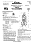
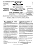
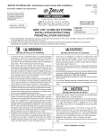
NOTICE TO INSTALLER: Instructions must remain with installation.
FM1613
0609
Supersedes
0409
P.O. BOX 16347 • Louisville, KY 40256-0347
3649 Cane Run Road • Louisville, KY 40211-1961
(502) 778-2731 • 1 (800) 928-PUMP • FAX (502) 774-3624
visit our web site:
www.zoeller.com
MODELS 580 & 585
BATTERY BACKUP PEDESTAL SUMP PUMP
PREINSTALLATION CHECKLIST
1. Inspect your pump. Occasionally, products are damaged during shipment. If the unit or any of the parts are damaged, contact your dealer
before using.
2. Read all the installation instructions regarding installing and start up. Retain for future reference.
SEE BELOW FOR LIST OF WARNINGS
1. Testing for Ground. As a safety measure each electrical outlet
should be checked for ground using an Underwriters Laboratory
listed circuit analyzer, which will indicate if the power, neutral and
ground wires are correctly connected to your outlet. If they are
not, call a qualified licensed electrician.
2. For your protection always disconnect the power supply from
its power source before handling the components of your DC
backup pump or the primary pump.
3. Installation and checking of electrical circuits and hardware should
be performed by a qualified, licensed electrician.
4. All electrical and safety codes must be followed in addition to the
National Electrical Code and all applicable local codes.
5.
It is the owner’s responsibility to check the battery
and battery connection at least once a month. Batteries contain acid and caution must be taken when
handling.
6. Risk of electric shock - These pumps have not been investigated
for use in swimming pool areas.
7. According to the state of California (Prop 65), this product contains
chemicals known to the state of California to cause cancer and
birth defects or other reproductive harm.
SEE BELOW FOR LIST OF CAUTIONS
1. Make sure there is a properly grounded 115V receptacle available. Do not use primary pump circuit. The location must be within
6' of the control box and battery. The power supply for your DC
control system plugs directly into the 115V outlet. DO NOT USE
AN EXTENSION CORD.
2. Make sure the 115V electrical supply circuit is equipped
with fuses or circuit breakers of proper capacity.
3. DC emergency pumps are designed for handling clear water. Do
not use in septic tanks to pump effluent or sewage pits to pump
sewage.
4. Repair and service of your DC backup system should be performed
by an authorized service station.
5. The installation of DC automatic backup pumps requires the use
of a variable level float switch for operation. It is the responsibility
of the installing party, to ensure that the tethered float switch will
not hang up on the pump apparatus or pit peculiarities and is
secured so the pump will turn “on” and “off”. It is recommended
that the pit be 18" in diameter or larger to accommodate both a
primary and a DC backup pump.
REFER TO WARRANTY ON PAGE 2.
© Copyright 2009 Zoeller Co. All rights reserved.
P/N 011952
Product information presented
here reflects conditions at time
of publication. Consult factory
regarding discrepancies or
inconsistencies.
SECTION: 6.10.079
Limited Warranty
Manufacturer warrants, to the purchaser and subsequent owner during the warranty period, every new product to be free from defects
in material and workmanship under normal use and service, when
properly used and maintained, for a period of one year from date of
purchase by the end user, or 18 months from date of original manufacture of the product, whichever comes first. Parts that fail within
the warranty period, one year from date of purchase by the end user,
or 18 months from the date of original manufacture of the product,
whichever comes first, that inspections determine to be defective in
material or workmanship, will be repaired, replaced or remanufactured
at Manufacturer's option, provided however, that by so doing we will
not be obligated to replace an entire assembly, the entire mechanism
or the complete unit. No allowance will be made for shipping charges,
damages, labor or other charges that may occur due to product failure,
repair or replacement.
This warranty does not apply to and there shall be no warranty for
any material or product that has been disassembled without prior approval of Manufacturer, subjected to misuse, misapplication, neglect,
alteration, accident or act of God; that has not been installed, operated
or maintained in accordance with Manufacturer's installation instructions; that has been exposed to outside substances including but not
limited to the following: sand, gravel, cement, mud, tar, hydrocarbons,
hydrocarbon derivatives (oil, gasoline, solvents, etc.), or other abrasive
or corrosive substances, wash towels or feminine sanitary products,
etc. in all pumping applications. The warranty set out in the paragraph
above is in lieu of all other warranties expressed or implied; and we
do not authorize any representative or other person to assume for us
any other liability in connection with our products.
Contact Manufacturer at, 3649 Cane Run Road, Louisville, Kentucky
40211, Attention: Customer Service Department to obtain any needed
repair or replacement of part(s) or additional information pertaining
to our warranty.
MANUFACTURER EXPRESSLY DISCLAIMS LIABILITY FOR SPECIAL, CONSEQUENTIAL OR INCIDENTAL DAMAGES OR BREACH
OF EXPRESSED OR IMPLIED WARRANTY; AND ANY IMPLIED
WARRANTY OF FITNESS FOR A PARTICULAR PURPOSE AND
OF MERCHANTABILITY SHALL BE LIMITED TO THE DURATION
OF THE EXPRESSED WARRANTY.
Some states do not allow limitations on the duration of an implied
warranty, so the above limitation may not apply to you. Some states
do not allow the exclusion or limitation of incidental or consequential
damages, so the above limitation or exclusion may not apply to you.
This warranty gives you specific legal rights and you may also have
other rights which vary from state to state.
Note: The purchase of an Aquanot® Battery from Zoeller Pump Company will extend the Limited Warranty to three years from date of installation.
Note: Three year limited warranty valid only when a complete system is purchased and used as a backup to a primary dewatering system. A
complete system includes a Model 580 or 585 Aquanot® Pump, Monitor/Charger, and an Aquanot Battery.
Carbon Monoxide Detectors
Whether you have an Aquanot® Battery Backup Sump Pump System, or a competitive brand, all batteries give off gaseous by-products when
charging. Some of these by-products can produce a rotten egg odor. Also, some of these by-products can cause a CO detector to falsely
activate. In order to help prevent false activation, Zoeller recommends moving the battery as far apart from the CO detector as possible or, if
necessary, vent the battery to the exterior. Zoeller provides the previous statements only as guidelines to help prevent false activation of the
CO detector. In no way are they meant to supersede the instructions that accompany the detector nor do they supersede advice from the CO
detector manufacturer.
If the audible alarm associated with your CO detector is activated, we recommend the following actions:
1)
Take immediate action for personal safety as recommended in the CO detector literature.
2)
Contact the appropriate agency to determine if the CO is being produced by your furnace, water heater, or any other device which uses
natural gas.
3)
If you are certain that no CO is being produced, then a charging battery may be producing gaseous by-products which are causing the
CO detector to activate. Contact the manufacturer of the CO detector, and ask for recommendations as to what can be done to prevent
the alarm activation.
© Copyright 2009 Zoeller Co. All rights reserved.
2
Ten Helpful Hints For Easy Installation
1. Remove all debris from pit before installation.
6. The battery & charger should be placed on a shelf.
2. Use a deep cycle battery only. Refer to battery descriptions on page 6.
7. Check float On/Off levels per STEP 2 of instructions.
3. Be sure the pump is on a firm, level surface.
8. Apply grease to the Positive and Negative terminals
of the battery to prevent corrosion.
4. Install a serviceable check valve in the discharge
line.
9. Check the battery water level once a month and add
distilled water as necessary.
5. Test the unit immediately after installation. Refer to
STEP 6.
10. Obtain model number, date code and installation instructions before calling factory.
Do’s And Don’t’s For Installing A Unit
NOT carry or lift pump by its power cord. DO NOT use
an extension cord with the Aquanot®. DO NOT lengthen
battery/pump leads.
1. DO read all installation material with the pump and
charger.
2. DO inspect unit for any visible damage caused by shipping. Contact dealer if unit appears to be damaged.
5. DO install union check valve (see step 3) in the discharge line. DO NOT use a discharge pipe smaller
than the recommended pump discharge sizes.
3. DO clean all debris from the pit.
4. DO always disconnect pump from power source before
handling. DO always connect to a separately protected
and properly grounded ground fault protected circuit.
DO NOT ever cut, splice or damage power cord. DO
6. DO test pump immediately after installation to be sure
that the system is working properly.
7. DO review all applicable local and national codes and
verify that the installation conforms to each of them.
TOTAL DYNAMIC HEAD
8
6
FEET
METERS
Performance Characteristics
TOTAL DYNAMIC HEAD/FLOW
PER MINUTE
EFFLUENT AND DEWATERING
PUMP PERFORMANCE CURVE
MODEL 580/585
25
20
15
4
10
585
2
5
580
0
5
GALLONS
LITERS
0
20
10
40
15
60
20
80
25
30
100
120
35
40
140
45
160
50
180
55
200
FLOW PER MINUTE
MODEL
585
Feet
Meters
5
1.5
10
3.0
15
4.6
Shut-off Head:
Gal.
Liters
49
186
36
136
25
95
20 ft.(6.1m)
MODEL
580
Feet
Meters
5
1.5
10
3.0
15
4.6
Shut-off Head:
Liters
Gal.
44
167
31
117
13
49
17 ft.(5.2m)
011922
Note: Aquanot® II (Model 585) data was developed with the charger supplying DC power to the pump.
© Copyright 2009 Zoeller Co. All rights reserved.
3
STEP 1
Placement of the Pump in the Pit
Note: If your pit has a cover, then it will have to be modified to accept the
Aquanot®.
1.1) Inspect the pit for debris and clean as necessary
ON/OFF SWITCH
PUMP MOTOR
1.2) Place the pump in the pit making certain that it is on a stable level
surface. Refer to Figure 1.1.
MAIN DISCHARGE
LINE
IMPORTANT: If this pump is to be used as a backup to your primary pump,
then make certain that there is no interference between the two pumps.
PRIMARY PUMP
The motor is not watertight. It should NEVER be below floor level.
22 MIN.
If necessary, bricks or similar materials, can be placed under the Aquanot®.
BRICK OR SIMILAR
MATERIAL
This product is meant to be used as a battery backup pump to
your primary pump only. Consult factory for advice before installing this unit
as a primary pump.
STEP 2
18 MIN.
SK1775
Figure 1.1
Float Stop Adjustment
2.1) With the pump in the pit, measure the desired float stop on/off positions as shown in Fig. 2.1. These two dimensions will determine the on/off levels of the pump. The spacing between the upper and lower stops will determine
the amount of water removed from the pit.
Note: It may be necessary to raise the float rod guide to adjust the stops to the dimensions determined in Step 2.1.
The float rod guide should NEVER be between the upper and lower stop.
2.2) Remove the pump from the pit and adjust the float stops as necessary. Tighten all screws.
Note: If a brick, or similar material has been used to raise the pump in the pit, it will be necessary to account for the
thickness of the brick.
UPPER
STOP
"ADJUST" ON/OFF POSITIONS
UPPER
STOP
"ON"
HEIGHT
"OFF"
HEIGHT
FLOAT ROD
GUIDE
LOWER
STOP
MAIN DISCHARGE
LINE
PRIMARY PUMP
LOWER
STOP
"ON"
HEIGHT
"OFF"
HEIGHT
Figure 2.1
SK1776
© Copyright 2009 Zoeller Co. All rights reserved.
4
Figure 2.2
SK1777
STEP 3
Installation of the Discharge Piping
3.1) Assemble the discharge pipe into the pump as shown in Figure 3.1.
CHECK VALVE
IMPORTANT: In order for this installation to work properly, a check valve
must be installed onto the discharge line.
P/N 30-0100
P/N 30-0101
P/N 30-0102
P/N 30-0103
}
CHECK VALVE
MAIN
DISCHARGE
LINE
MAIN
DISCHARGE
LINE
PRIMARY PUMP
PRIMARY PUMP
Recommend the following Zoeller check valves:
Some local codes require union check with ball valve.
OR
Figure 3.1
STEP 4
SK1778
Electrical Connections for Model 585
Note: This Step is for the Aquanot® II (Model 585). Proceed to STEP 5
for installation of Aquanot® I (Model 580).
POSITIVE(+)
BATTERY TERMINAL
BATTERY
NEGATIVE(-)
BATTERY TERMINAL
RED LEAD
TO POSITIVE(+)
BLACK LEAD
TO NEGATIVE (-)
4.1) Complete electrical connections as shown in Figure 4.1.
4.2) Proceed to STEP 6.
CHARGER
BLACK LEAD
TO NEGATIVE(-)
Do not place battery or charger directly on ground. If the
battery or charger must be placed directly on the ground, then place a
piece of wood between the units and the ground. Do not put the charger
on top of the battery.
OUTLET
RED LEAD
TO POSITIVE(+)
ALARM
MOTOR
SWITCH
CUT AWAY OF SUMP PIT
Figure 4.1
STEP 5
SK1783
Electrical Connections for Model 580
5.1) Complete the electrical connections as shown in Figure 5.1.
Do not place battery or monitor directly on ground. If
the battery or monitor must be placed directly on the ground, then
place a piece of wood between the units and the ground. Do not
put the battery monitor on top of the battery.
Figure 5.1
STEP 6
6.1)
6.2)
6.3)
6.4)
6.5)
SK1784
Testing of Pump Operation
Unplug the primary pump so that it does not start.
Fill pit with water until the Aquanot® starts.
Verify that the pump starts and stops at the desired on/off points.
Verify that there are no leaks in the discharge line.
If adjustment is necessary, raise or lower the appropriate stop(s) according to STEP 2.
IMPORTANT: Spacing between upper and lower stops determine amount of water removed from pit.
6.6) If the pump is not operating properly after following the above steps, refer to the Troubleshooting guide on page 8.
6.7) When finished testing plug primary pump back into AC receptacle.
© Copyright 2009 Zoeller Co. All rights reserved.
5
Operation of the Aquanot® Charger (Model 585 Only)
The charger automatically monitors and charges your battery. In the event of a power outage the pump will be powered by the
battery. Once line power is restored, the charger will recharge the battery. If there is a failure of the primary pump, the charger will
supply power to the pump through the battery if line power is present; otherwise, the battery will take over until the problem has
been corrected.
The lights on the front panel of the charger indicate the state of system:
The red light: Indicates that AC line power is present.
The green light: Indicates that the battery is charged to 12V DC*.
During periods of extended power outage the charge on the battery may drop below 12V DC which would cause the green
light to go out. This is normal. The green light will be illuminated once the charger restores the voltage level to 12V DC.
The yellow light: Indicates that the battery is charged above 8V DC.
If the yellow light is not illuminated, it indicates that the charge on the battery is below 8V DC. If the line power is out, the pump
may have depleted the battery due to normal operation. If there has been no power outage and the primary pump is working
properly, it may indicate that the battery is defective or that the controller is defective. Refer to the Troubleshooting guide on
page 8 for further instructions.
If the Green and Yellow lights flash intermittently, refer to Section G in the Trouble Shooting Guide on page 8.
*Voltage is only one indicator of the state of the battery, and does not reflect the true condition of the battery. Use a hydrometer to
more accurately determine the condition of the battery.
Operation of the Audible Alarm (All Models)
All Aquanot® pump systems are equipped with an alarm which sounds when the pump is activated. The alarm will automatically
silence when the pumping cycle is completed.
Activation of the audible alarm indicates that the primary pump has failed or line power to the primary pump is not present. Whenever the alarm is activated the primary pump and outlet should be inspected.
The On/Off switch, located on the side of the alarm enclosure, allows the audible alarm to be turned off, however, this practice is
not recommended. Verify that the alarm switch is in the “on” position, by manually turning the pump “on”.
The Aquanot® Battery
There are millions of batteries manufactured each year, so it is impossible to guarantee consistent quality. A defective battery
will never become fully charged and may damage the circuits of the charger. It is for this reason that Zoeller offers its own line of
batteries. We offer both a Water/Acid Deep-Cycle Battery which can run the pump continuously for over 7½ hours, and an AGM
battery, which will power the pump for over 3½ hours. These times are based on continuous pumping at 10’ of static head. Actual
times will vary depending on static head, volume of water entering the pit, and the condition of the battery.
Follow these recommendations:
•
•
•
•
•
•
Use a B.C.I. size 27 deep-cycle battery, 175 minute reserve capacity, or larger.
Do NOT use a “maintenance-free” battery unless it is Gel-filled or AGM battery.
Replace your battery every 3 years.
Do not let corrosion build up on the battery terminals.
Do not place your battery on a concrete floor where it will discharge faster.
To check specific gravity, follow the instructions on a hydrometer (not applicable for Gel or AGM batteries).
PROTECT YOUR WARRANTY:
•
Water level in batteries must be checked once a month (not applicable for Gel or AGM batteries).
© Copyright 2009 Zoeller Co. All rights reserved.
6
SK1786
Illustrated Parts Breakdown
MODELS:
REF.
NO.
DESCRIPTION
QTY
580-A
580-B
580-C 580-D
580-E
585-A
585-B
585-C
585-D
585-E
585-F
585-G
1
Motor Brushes
2
011882
011882
011882
013878
*Consult
Factory
011882
011882
011882
011882
013878
*Consult
Factory
*Consult
Factory
2
Pump Alarm
1
012485
012485
012485
012485
012485
012485
012485
012485
012485
012485
012485
012485
3
Pump Switch
1
011990
011990
017205
017205
017205
011990
011990
011990
017205
017205
017205
017205
4
Float Kit & Cable
1
012109
012109
012709
012709
012709
012109
012109
012109
012709
012709
012709
012709
5
Lead Wires
1
012401
012401
012401
012401
012401
012401
012401
012401
012401
012401
012401
012401
6
Terminal Spade
1
004442
004442
004442
004442
004442
004442
004442
004442
004442
004442
004442
004442
7
Terminal Ring
1
011939
011939
011939
011939
011939
011939
011939
011939
011939
011939
011939
011939
8
Pump Motor
1
013873
013873
013873
013873
013873
013873
013873
013873
013873
013873
013873
013873
9
Column
1
011942
011942
011942
011942
011942
011942
011942
011942
011942
011942
011942
011942
011940
10
Adapter, Drive
1
011940
011940
011940
011940
011940
011940
011940
011940
011940
011940
011940
11
Shaft
1
011944
011944
011944
011944
011944
011944
011944
011944
011944
011944
011944
011944
12
Head w/Brass Bearing
1
011947
012137
012137
012137
012137
011947
011947
012137
012137
012137
012137
012137
13
Washer, Thrust
1
002140
002140
002140
002140
002140
002140
002140
002140
002140
002140
002140
002140
14
Impeller
1
011945
011945
011945
011945
011945
011945
011945
011945
011945
011945
011945
011945
15
Base Plate
1
011948
012138
012138
012138
012138
011948
011948
012138
012138
012138
012138
012138
16
Screws
8
011949
012118
012118
012118
012118
011949
012118
012118
012118
012118
012118
012118
17
Guide, Float Rod
1
N/A
N/A
003903
003903
003903
N/A
N/A
N/A
003903
003903
003903
003903
18
Battery Charger (585 Only)
1
N/A
N/A
N/A
N/A
N/A
012309
012298
012298
012298
012298
012298
150160
19
Battery Monitor (580 Only)
1
012484
012484
012484
012484
012484
N/A
N/A
N/A
N/A
N/A
N/A
N/A
20
Pump 580/585
1
585-0006
585-0006
585-0006
585-0006
585-0006
585-0006
585-0006
585-0006
585-0006
585-0006
585-0006
585-0006
21
Float
1
N/A
N/A
012707
012707
012707
N/A
N/A
N/A
012707
012707
012707
012707
22
Stop, Float
2
N/A
N/A
054085
054085
054085
N/A
N/A
N/A
054085
054085
054085
054085
23
Rod, Float
1
N/A
N/A
012706
012706
012706
N/A
N/A
N/A
012706
012706
012706
012706
24
Screws
1
N/A
N/A
003925
003925
003925
N/A
N/A
N/A
003925
003925
003925
003925
012353
*Consult
Factory
012353
*Consult
Factory
*Consult
Factory
25
Fuse, 30 Amp
1
011927
012353
012353
011927
012353
012353
012353
*Advise motor Leeson or CIM.
Before servicing a pump, always shut off the main
power breaker and then unplug the pump - making sure you
are not standing in water and are wearing insulated protective
sole shoes. Under flooded conditions, contact your local electric
company or a qualified licensed electrician for disconnecting electrical
service prior to pump removal.
If the following checklist does not solve the problem, consult Zoeller’s
Technical Service Department 1-(800) 928-7867 - Do not attempt to
service or otherwise disassemble pump.
© Copyright 2009 Zoeller Co. All rights reserved.
7
Troubleshooting Guide
CONDITION
POSSIBLE CAUSE
Low voltage, blown fuse open circuit.
REMEDY
Have a qualified electrician check fuse and circuit.
Impeller bound.
Replace fuse.
A
PUMP WILL NOT START OR RUN.
Blown pump fuse.
Defective Switch
Contact factory.
Motor or wiring shorted.
B
C
D
E
F
G
H
PUMP STARTS TOO SOON.
PUMP WILL NOT SHUT OFF.
PUMP OPERATES BUT DELIVERS LITTLE
OR NO WATER.
RED LIGHT ON CHARGER (MODEL 585)
IS OUT.
RED LIGHT FLASHING (MODEL 585).
Float “ON” point is adjusted too low.
Refer to STEP 2.
Float is obstructed.
Inspect float operation and correct problem.
Float “Off” point adjusted too low.
Adjust “Off” point. Refer to STEP 2.
Faulty float switch.
Contact factory.
Debris around intake.
Clean area around intake.
Blockage in discharge pipe.
Remove pipe and flush out debris.
Low voltage.
Check condition of battery. Replace as necessary or
recharge.
Blown fuse, open circuit.
Have a qualified electrician check circuit.
Incorrect float adjustment
Refer to STEP 2 for proper installation.
Pump is air locked.
Drill ¼” hole in discharge pipe below waterline.
Vertical lift too high.
Change discharge piping or contact tech. service.
Base plate is “loose” or corroded.
Remove pump from pit and tighten as necessary.
Pump runs in reverse.
Make certain that the red(+) lead and black(-) leads go to
the appropriate battery terminals.
Damaged Impeller.
Contact factory.
Power outage.
Normal condition Red light will be illuminated once line
power is restored.
AC line fuse blown.
Have a qualified electrician replace with new fuse on the
circuit board.
Defective controller or light burned out.
Contact factory.
No AC power, battery less than 5V.
Battery has depleted below 5V due to prolonged operation
without AC power. Call for service or replace battery.
The charger fan may be defective.
Have a qualified electrician inspect the charger.
Positive & Negative battery leads are
reversed.
Make certain that the positive (red) & negative (black) leads
go to the proper battery terminals.
Battery maintenance required.
Check water lever of battery, refill as necessary (Do not
overfill).
Defective battery. Replace as necessary.
GREEN & YELLOW LIGHTS FLASH
INTERMITTENTLY (MODEL 585).
Battery has a “Dead Short”.
Replace battery. Battery has aged beyond its ability to
chemically store electricity.
Loose battery connections.
Tighten red and black battery leads.
Corroded battery terminals.
Clean terminal as necessary. Apply grease to terminals to
prevent future corrosion problems.
Battery voltage hasd dropped below 8V.
Battery depleted below 8V due to normal operation. Will
be illuminated once AC power is restored and battery is
charged.
YELLOW LIGHT IS OUT (MODEL 585).
Battery may be defective.
Replace battery.
Light may be defective.
Contact factory.
I
GREEN LIGHT IS OUT
Battery voltage has dropped below
12V.
Battery depleted below 12V due to normal operation. Will
be illuminated once AC power is restored and battery is
charged.
Light may be defective.
Contact factory.
J
RED, GREEN & YELLOW LIGHTS FLASH
IN SEQUENCE (MODEL 585).
Lights flash for approximately for 4
seconds.
Normal condition. The lights indicate that the system is
properly installed.
CONSTANTLY ADDING DISTILLED WATER
TO BATTERY.
Defective battery.
K
Have battery inspected. The charger will overcharge a
battery with a defective cell.
Defective controller.
Contact factory.
Charger is overcharging battery.
Have battery inspected. The charger will overcharge a
battery with a defective cell.
L
ROTTEN EGG SMELL IN BASEMENT.
© Copyright 2009 Zoeller Co. All rights reserved.
8