1
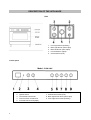
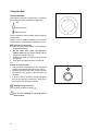
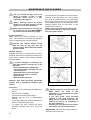
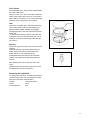
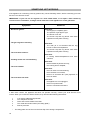
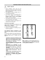
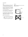
MIXED
FUEL
COOKER
ZCM930X
INSTRUCTION BOOKLET
GB
Please read this instruction booklet before using the appliance.
IMPORTANT SAFETY INFORMATION
You MUST read these warnings carefully before installing or using the appliance. If
you need assistance, contact our Customer Care Department on 08705 727727.
Installation
·
·
·
·
·
·
This cooker must be installed by qualified
personnel, according to the manufacturer’s
instructions and to the relevant British
Standards.
This cooker is heavy. Take care when
moving it.
Any gas installation must be carried out by a
registered CORGI installer.
Remove all packaging before using the
cooker.
Ensure that the gas and electrical supply
complies with the type stated on the rating
plate, located near the gas supply pipe.
Do not attempt to modify the cooker in any
way.
Child Safety
·
·
·
This cooker is designed to be operated by
adults. Do not allow children to play near or
with the cooker.
The cooker gets hot when it is in use.
Children should be kept away until it has
cooled.
Children can also injure themselves by
pulling pans or pots off the cooker.
During Use
·
·
·
·
2
This cooker is intended for domestic cooking
only. It is not designed for commercial or
industrial purposes.
When in use a gas cooker will produce heat
and moisture in the room in which it has
been installed. Ensure there is a continuous
air supply, keeping air vents in good
condition or installing a cooker hood with a
venting hose.
When using the cooker for a long period
time, the ventilation should be improved, by
opening a window or increasing the extractor
speed.
Do not use this cooker if it is in contact with
water. Do not operate the cooker with wet
hands.
·
·
·
·
·
·
·
·
·
The grill pan will become hot during use,
always use oven gloves when removing or
replacing a hot grill pan.
Ensure the control knobs are in the ‘OFF’
position when not in use.
When using other electrical appliances,
ensure the cable does not come into contact
with the hot surfaces of the cooker.
Unstable or misshapen pans should not be
used on the hob burners as unstable pans
can cause an accident by tipping or spillage.
Never leave the cooker unattended when
cooking with oil and fats.
This cooker should be kept clean at all
times. A build-up of fats or foodstuffs could
result in a fire.
Never use plastic dishes in the oven or on
the hob burners. Never line any part of the
oven with aluminium foil.
Always ensure that the oven vent, which is
located at the centre back of the hob, is left
unobstructed to ensure ventilation of the
oven cavity.
Perishable food, plastic items and aerosols
may be affected by heat and should not be
stored above the cooker.
Service
·
This cooker should only be repaired or
serviced by an authorised Service Engineer
and only genuine approved spare parts
should be used.
Environmental Information
·
·
After installation, please dispose of the
packaging with due regard to safety and the
environment.
When disposing of an old appliance, make it
unusable, by cutting off the cable.
Keep this instruction book for future
reference and ensure it is passed on to
any new owner.
CONTENTS
Instructions for the user
Instructions for the installer
Important Safety Information
2
Technical Features
21
Description of the appliance
4
Safety Advice
22
Using the appliance
- Using the conventional oven
- Using the fan oven
- Using the grill
- Using Hot Air Grilling
- Using Defrost
- Hints & Tips
- Using the Hob
- Electronic Timer
5
6
8
9
10
10
11
12
13
Electrical connection
23
Technical Data
25
Installation
- Positioning
- Ventilation
- Location
25
26
26
16
Gas connections
27
Maintenance and Cleaning
18
Gas Conversion
28
Something Not Working
Service & Spare Parts
19
Customer Care
19
Guarantee conditions
20
How to read the instruction book
The symbols below will guide you when reading the
instruction book
Safety instructions
Step by Step Operation
Advice and recommendations
3
DESCRIPTION OF THE APPLIANCE
Hob
1.
2.
3.
4.
5.
Front right burner (auxiliary)
Back right burner (semi-rapid)
Back left burner (semi-rapid)
Front left burner (rapid)
Central burner (wok)
Control panel
Model : ZCM 930X
1.
2.
3.
4.
5.
4
Electronic Timer
Ignition switch
Thermostat control knob
Oven Function control knob
Front left burner knob (rapid)
6.
7.
8.
9.
Back left burner knob ( semi-rapid)
Central burner knob (wok)
Back right burner knob (semi-rapid)
Front right burner knob (auxiliary)
USING THE APPLIANCE
Oven function control knob
OFF
Light
Conventional Oven – The heat comes
from both the top and bottom elements.
Top Element – The heat comes from the
top element only.
Bottom Element – The heat comes from
the bottom element only.
Single Grill – The single inner grill
element will switch on.
Dual Grill – Both the inner and outer grill
elements will come on.
Hot Air Grilling – This is an alternative
method of cooking associated with foods
that are normally cooked with the grill.
The grill element and fan operate.
Fan Oven – This allows roasting and/or
baking on any shelf simultaneously.
Defrost function – The fan operates
without heat.
Thermostat control knob
Turn the thermostat control knob clockwise to
select temperatures between 50°C and 250°C
(MAX).
Thermostat control light
The thermostat control light will come on when
the thermostat control knob is turned. The light
will remain lit until the correct temperature is
reached. It will then cycle on and off to show that
the temperature is being maintained.
Main oven light
This light will illuminate when the oven/grill knob
is turned on and remains lit while the oven is in
operation.
5
Before the First Use of the Cooker
Before first use ensure that the room is
well ventilated, V.M.C. (Mechanic
ventilation), or a window is open.
Remove all packaging both inside and
outside of the cooker, before using it.
Before first use, the oven should be heated
without food. During this time, an unpleasant
odour may be emitted. This is quite normal.
1. Remove the oven accessories.
2. Detach the adhesive labels and any foil
protection if there is any.
3. Turn the oven function control knob to
conventional cooking.
4. Turn the thermostat control knob to 250°C.
5. Allow the oven to run for about 30 min.
This procedure should be repeated with the grill
for about 10 min.
Clean the accessories with a mild detergent. Rinse
and dry carefully.
During cooking in the oven the oven
door will become hot. Take care that
children do not play near it.
During use the appliance becomes
hot. Care should be taken to avoid
touching heating elements inside the
oven.
Using the Conventional Oven
Set the function control knob to Conventional oven
and select the desired temperature using the
thermostat control knob and wait until the orange
light goes out off before putting any food in the
oven.
The oven is equipped with 5 shelf positions at
different heights which can be used to insert
shelves or the tray. To keep the oven as clean as
possible it is recommended that meat is cooked
on the tray or on the shelf that has been inserted
inside the tray.
The table on the following page lists the cooking
times and the position of the tray for different
types of foods. The times quoted should be used
as a guide only, it may be necessary to increase
or decrease the temperature to suit individual
requirements. Only experience will enable you to
determine the correct setting for your personal
requirements.
6
Conventional Oven Cooking Chart
Food
Meat
Roast Pork
Roast Beef
Roast Veal
Roast Lamb
Roast Hare
Roast Rabbit
Roast Turkey
Roast Goose
Roast Duck
Roast Chicken
Temp °C
Shelf Position
Minutes
225
250
225
225
250
250
250
225
250
250
4/5
4/5
4/5
4
4/5
4
4
4
4/5
4/5
60-80
50-60
60-80
40-50
40-50
60-80
50-60
60-70
45-60
40-45
Fish
200-225
3
15-25
Pastry
Fruit Pie
Tea Cake
Brioches
Sponge Cake
Ring Cake
Sweet Puff Pastries
Raisin Loaf
Strudel
Apple Fritters
Toast Sandwich
Bread
Pizza
225
175-200
175-200
220-250
180-200
200-220
250
180
200-220
250
220
220
3
3
3
3
3
3
3
3
3
4
4
3
35-40
50-55
25-30
20-30
30-40
15-20
25-35
20-30
15-20
5
30
20
Using the top element only
This function is suitable for finishing cooked
dishes such as lasagne, shepherd’s pie and
cauliflower cheese.
Using the bottom element only
This function is particularly useful when blindbaking pastry. It can also be used to finish of
quiches or flans to ensure that the pastry base
is cooked through.
7
Using the fan oven
The air inside the oven is heated by the
element around the fan situated behind the
back panel. The fan circulates hot air to
maintain an even temperature inside the oven.
The advantages of fan cooking are:
Faster Preheating
As the oven quickly reaches temperature, it is
not usually necessary to preheat the oven
although you may find that you need to allow an
extra 5-7 minutes on cooking times.
For recipes which require higher temperatures,
best results are achieved if the oven is
preheated first, e.g. bread, pastries, scones
soufflés etc.
Lower Temperatures
Fan
oven
cooking
generally
requires
temperatures 20-25°C lower than conventional
cooking.
Even Heating for Baking
The fan oven has even heating on all shelf
positions. This means that batches of the
same food can be cooked in the oven at the
same time. There is no mixing of flavours.
Please note that shelf positions are counted
from the top downwards.
Fan Oven Cooking Chart
Food
Biscuits
Bread
Casseroles
Cakes
Small & Queen
Sponges
Rich Fruit
Christmas
Meringues
Fish
Fruit Pies & Crumbles
Milk Puddings
Pastry
Choux
Shortcrust
Flaky
Puff
Plate Tarts
Quiches / Flans
Scones
Roasting: Meat & Poultry
8
Shelf Position
3
4
3
3
3
3
3
4
3 or 4
3
3
Temp °C
180-190
210-220
130-140
160-170
160-170
130-140
130-140
90-100
170-190
190-200
130-140
3 or 4
190-200
4
3
3
4 or 5
180-190
170-180
210-220
180-190
Using the grill
Grilling
Turn the oven function control knob to either
. for the inner grill only or
for the dual grill.
Heat comes from the top of the oven. It is suitable
for grilling meat that remains tender, for toast or
to brown foods that are already cooked.
The grill pan will become hot during use,
always use oven gloves when removing
or replacing a hot grill pan.
When grilling, the accessible parts of the
appliance are hot. Take care that children
do not play near it.
Always grill with the door closed.
·
·
·
·
·
·
·
·
Prepare the meat to be grilled, lightly brush it
with oil on both sides.
Place it on the grill.
Turn the oven control knob to the appropriate
position.
Slide the shelf into position 1 or 2 depending
on the thickness of the meat to be grilled.
Use guide 2 for thick pieces to be roasted
(bacon, large fish, poultry).
When the first side is brown, turn the meat
without pricking it in order that the juices are
not lost.
Grill the second side.
Flavour when ending the cooking.
Cooking time has to determined by the thickness of
the piece to be grilled not by its weight.
Browning
·
·
·
Turn the oven knob to the appropriate
position.
Place the dish on the grid and slide it in the
guide 2 or 3.
Leave the dish under the radiation of the grill
for a few minutes.
9
Using Hot Air Grilling
This function uses both the grill element and the
fan.
Turn the function control knob to the
appropriate position.
To achieve optimum
cooking results, it is advisable to place the oven
shelf in the middle position while the oven tray
should be inserted at the bottom.
IMPORTANT: When using the hot air grilling
function, set the thermostat knob no higher
than 175°C, which is between the 150°C and
200°C setting, to avoid overheating the front
of the appliance.
The door MUST be closed while Hot Air
Grilling.
Using Defrost
Turn the oven function control knob to defrost and
ensure that the thermostat control knob is set to
OFF.
The fan operates without heat and circulates air, at
room temperature, inside the oven. This function is
particularly suitable for delicate foods which could be
damaged by heat, e.g. cream filled gateaux,
pastries, bread and other yeast products
Hints and Tips
Cover food with a lid, aluminium foil or plastic film to
prevent the food drying out during defrosting.
ALWAYS COOK THOROUGHLY IMMEDIATELY
AFTER THAWING.
Frozen food should be placed in a single layer when
ever possible and turned over half way through the
defrosting process.
Only joints of meat and poultry up to 2 kg. (4 lb.) are
suitable for defrosting in this way.
10
Hints and Tips
Condensation and steam
When food is heated it produces steam in the
same way as a boiling kettle. The oven vents
allow some of this steam to escape. However,
always stand back from the oven when
opening the oven door to allow any build up of
steam or heat to release.
If the steam comes into contact with a cool
surface on the outside of the oven, e.g. a trim, it
will condense and produce water droplets. This
is quite normal and is not a fault with the oven.
To prevent discolouration, regularly wipe away
condensation and also soilage from surfaces.
Cookware
Use any ovenproof cookware,
°
withstand temperatures of 250 C.
which
will
Oven dishes, etc. should not be placed
directly on the oven base.
Oven Cooking
· Turn off the oven 5 minutes before the end of
cooking time, and use residual heat to
complete the cooking.
· The thickness, the material and the colour of
the pan will influence the cooking results.
· When cooking, certain dishes increase in
volume, ensure the pan is large enough.
· To prevent fat dripping when roasting use tall
rim pans proportional to the item being
roasted.
· Prick the skin of poultry and sausages with a
fork before cooking to avoid spitting.
Use heatproof glass dishes for soufflés.
The effects of dishes on cooking results
Dishes and tins vary in their thickness,
conductivity, colour, etc. which affects the way
they transmit heat to the food inside them.
A Aluminium, earthenware, oven glassware and
bright shiny utensils reduce cooking and base
browning.
B Enamelled cast iron, anodised aluminium,
aluminium with non-stick interior and coloured
exterior and dark, heavy utensils increase
cooking and base browning.
11
Using the Hob
The Hob Burners
The symbol on the knob corresponds to a symbol on
the control panel (See description of appliance).
Off
Maximum level
Minimum level
Use the maximum level for boiling and the minimum
for simmering.
Always choose positions between the minimum
and maximum, never between maximum and off.
·
·
·
·
Ignition of the burners
Turn the knob anticlockwise to the Maximum
position (large flame)
At the same time, push the electronic
ignition knob (see fig). Keep it pushed until the
gas ignites (1 spark / second).
Release the knob and watch that the burner
has ignited.
Upon ignition, adjust the flame as required.
OR
If there is a power failure
· Turn the knob anticlockwise to the maximum
position (large flame) and ignite with a match.
· Release the knob and watch that the burner
has ignited. Upon ignition, adjust the flame as
required.
· If for any reason the flame should extinguish
turn off the relevant control know, leave for at
least one minute and then re-ignite.
Extinguishing of burners
Turn the knob clockwise to mark «
».
Do not put anything on the hob that is
liable to melt.
12
Good use
Selecting the Correct Burner
Above every knob there is a symbol for the
corresponding burner.
For good cooking results, always choose pans
which correctly fit to the diameter of the burner
used. Choose pans with thick, flat bases.
We recommend that the flame is lowered as soon
as the liquid starts boiling.
For correct ignition always keep the burner ring
and spark plugs clean.
Burner
Double
Ring
Rapid
SemiRapid
Auxiliary
Bad use
(Power waste)
Diameter (mm)
min.
max.
220
226
180
260
140
260
120
140
ELECTRONIC TIMER
Setting The Time
1. Press buttons 2 and 3 together. Release
the buttons.
2. Within five seconds, press the + button
until the correct time of day is shown.
The cookpot symbol will be showing.
The increase and decrease buttons operate
slowly at first, and then more rapidly. They
should be pressed separately.
The Minute Minder
1
2
3
4
5
1. Press and release button 1.
2. Within 5 seconds press the + button until
the display shows the time you want.
After a few seconds the display will again show
the time of day.
When you are using the minute minder you can
check the time remaining by pressing button 1.
At the end of the timed period an audible signal
will be heard. Switch off the alarm by pressing
button 1.
After a few seconds the time of day is shown in
the display.
13
To Switch The
Automatically
Oven
On
and
Off
1. Ensure that the clock is showing the
correct time of day.
2. Place the food in the oven.
3. Set the length of time you want the food
to cook for by pressing and releasing
button 2 and then pressing button 5 until
the correct cooking time is displayed.
This must be completed within 5 seconds
of pressing button 2.
The maximum cooking time is 23 hours
59 minutes.
The Cookpot and Auto symbols will show
in the display.
After a few seconds the time of day
shows in the display.
4. To set the time you want the food to be
cooked by, press and release button 3.
This will show you the earliest possible
stop time.
If this is different to the time you want the
food to be cooked by, press the + button
within 5 seconds until the correct stop
time shows in the display.
After a few seconds the time of day
shows in the display and the Cookpot
symbol goes out.
The 'Stop' time must not be more than 23
hours 59 minutes from the time of day.
For example, if the time of day is 09.00
hours (9.00am) the latest 'Stop' time will
be 08.59 (8.59am) the next day.
5. Turn the oven function to Fan oven and
the temperature control knob to the
correct setting.
The clock will work out what time the oven will
switch itself on and will switch the oven off at the
end. An audible signal will sound when cooking is
complete. To cancel the sound, see below.
14
Returning The Cooker To Manual Or To
Cancel An Automatic Programme
Once automatic cooking is complete an alarm will
sound and the Auto symbol will flash to remind
you that the oven needs to be set for manual
operation.
1. To do this press buttons 2 and 3 and
together.
After a few seconds the timer will show
the time of day. The cookpot will show in
the display and the oven will switch on
again.
2. Turn off the oven control.
To Set The Timer To Switch Off Only
This is useful if you want to begin cooking
immediately but have the Main Fan oven switch
off whilst you are out.
1. Ensure the clock is showing the correct
time of day.
2. Place food in the oven.
3. Set the length of time you want the food
to cook for. Press and release button 2
and then within 5 seconds press the
button until the correct cook time is
showing.
After a few seconds the time of day
shows in the display.
4. Turn the oven temperature control to the
required setting. The oven indicator neon
will come on.
If you want to check the time the oven
will switch off simply press the button and
the 'Stop' time will be displayed.
At the end of the cook time the oven will
switch off, the alarm will sound and the
auto symbol will flash.
5. To cancel and return to manual operation
press buttons 2 and 3 together.
6. Turn off the oven temperature and oven
function control knobs.
15
MAINTENANCE AND CLEANING
The oven should be kept clean at all
times. A build-up of fats or other
foodstuffs could result in a fire,
especially in the grill pan.
Before cleaning, ensure all control
knobs are in the OFF position, and the
appliance has cooled completely.
Before any maintenance or cleaning can
be carried out, you must DISCONNECT
the cooker from the electricity supply.
The internal oven door glass can be removed for
cleaning. To do this loosen the 2 fixing screws
(B). Clean the outer and inner door glass using
warm soapy water. Should the inner door glass
become heavily soiled it is recommended that a
cleaning product such as Hob Brite, or Bar
Keepers Friend be used.
Always support the door while removing the
glass panel as the door may spring closed
due to its lighter weight
Cleaning materials
Before using any cleaning materials on your
oven, check that they are suitable and that their
use is recommended by the manufacturer.
Cleaners that contain bleach should
NOT be used as they may dull the
surface finishes. Harsh abrasives should
also be avoided.
External cleaning
Regularly wipe over the control panel, oven door
and door seal using a soft cloth well wrung out in
warm water to which a little washing up liquid
has been added.
To prevent damaging or weakening the
door glass panels avoid the use of the
following:
• Household detergent and bleaches
• Impregnated pads unsuitable for non
stick saucepans
• Brillo/Ajax pads or steel wool pads
• Chemical oven pads or aerosols
• Rust removers
• Bath/Sink stain removers
Stainless steel parts should be periodically
cleaned with a proprietary stainless steel
cleaner.
Oven Door
- The door can be dismantled for cleaning as
follows:
- Open the door completely
- Insert hook C into the hinged part D.
- Partially close the door. to approximately
half-way.
- Using both hands, pull the door towards you
until it is released from the hinge.
- To replace the door, reverse the above
procedure ensuring that part F locks into
place.
16
DO NOT clean the oven door while the
glass panels are warm. If this
precaution is not observed the glass
panel may shatter.
If the door glass panel becomes
chipped or has deep scratches, the
glass will be weakened and must be
replaced to prevent the possibility of
the panel shattering.
Contact your local Service Force Centre
who will be pleased to advise further.
IMPORTANT: The inner door glass must be in
place when using the oven.
Oven Cavity
The enamelled oven cavity is best cleaned whilst
the oven is still warm.
Wipe the oven over with a soft cloth soaked in
warm soapy water after each use. From time to
time it will be necessary to do a more thorough
cleaning, using a proprietary oven cleaner.
Hob
After every use wipe with a soft cloth well wrung
out in warm water to which a little washing up
liquid has been added, avoiding any leakage
through the holes of the hob. Rinse and dry with
a soft cloth.
To remove more stubborn stains, wet and leave
to dissolve, do not scratch and avoid the use of
abrasive or caustic products that could damage
the enamel.
Burner cap
Burner
ring
Ignition
Burners
The burner caps and crowns can be removed for
cleaning.
Wash the burners caps and crowns using hot
soapy water, and remove marks with a mild
paste cleaner. A well-moistened soap
impregnated steel wool pad can be used with
caution, if the marks are particularly difficult to
remove.
After cleaning, be sure to wipe dry with a soft
cloth.
Always ensure that the burner caps and crowns
are replaced in the correct positions.
Replacing the Light Bulb
To replace the oven bulb, unscrew the protection
cap in the roof of the oven and replace the bulb
with one of the same characteristics.
Voltage
230-240V (50Hz)
Power
25 W
Connection size
E14
17
SOMETHING NOT WORKING
If the appliance is not working correctly, please carry out the following checks, before contacting your local
Service Force Service Centre.
IMPORTANT: If you call out an engineer to a fault listed below, or to repair a fault caused by
incorrect use or installation, a charge will be made even if the appliance is under guarantee.
Symptoms
1. No burner ignition
2. The gas ring burns unevenly
Solutions
Check that:
· Gas supply is completely open
· The position of gas pipe is right
· The burner is not wet
· The burner cap and ring burner have been
replaced correctly after cleaning
Check that:
· The main jet is not blocked and the ring
burner is clean of food particles
· The burner cap and ring burner have been
replaced correctly after cleaning
3. The oven does come on
4. Cooking results are not satisfactory
5. The oven smokes
6. The oven does not work
Check that:
· a cooking function/temperature have been
selected;
Check that:
· the thermostat is placed correctly;
· the cooking time is adapted;
Check that:
· the oven does not need cleaning;
· the meal does not overflow;
· there is no excessive fat / juice projection on
the oven sides.
Check that:
· the appliance is not unplugged;
· there is no power break.
· the fuse connections are intact.
If after these checks, the appliance still does not operate correctly, contact your local Service Force
Centre. When you contact the Service Centre, they will need the following information:
1
2
3
4
5
*
18
Your name, address and postcode.
Your telephone number
Clear and concise details of the fault
The model and serial number (see rating plate*)
Date of purchase
The rating plate can be found on the front flap of the storage compartment.
SERVICE & SPARE PARTS
If you require spare parts or an engineer contact your local Service Force Centre by telephoning:
08705 929 929
Your call will be routed to the Service Centre covering your postcode area.
For the address of your local Service Force Centre and further information about Service Force, please
visit the website at www.serviceforce.co.uk
Before calling out an engineer, please ensure you have read the details under the heading “Something Not
Working” and have the model number and purchase date to hand.
In-guarantee customers should ensure that the checks under the heading “Something Not
Working” have been made as the engineer will make a charge if the fault is not a mechanical or
electrical breakdown.
Please note that it will be necessary to provide proof of purchase for any in-guarantee service
calls.
CUSTOMER CARE
For general enquiries concerning your Zanussi appliance or for further information on our products, contact
our Customer Care Department by letter or telephone at the address below or visit our website at
www.zanussi.co.uk
Customer Care Department
Zanussi
55-77 High Street
Slough
Berkshire SL1 1DZ
Tel: 08705 727 727 (*)
(*) Calls may be recorded for training purposes.
19
GUARANTEE CONDITIONS
Standard Guarantee Conditions
We Zanussi undertake that if, within 12 months of the date of the purchase, this Zanussi appliance or any
part thereof is proved to be defective by any reason only of faulty workmanship or materials, we will, at our
option, repair or replace the same FREE OF ANY CHARGE for labour, materials or carriage on condition
that:
· The appliance has been correctly installed and used only on the gas and electricity supply stated on the
rating plate.
· The appliance has been used for normal domestic purposes only, and in accordance with the
manufacturer's instructions.
· The appliance has not been serviced maintained, repaired, taken apart or tampered with by any person
not authorised by us.
· All service work under this guarantee must be undertaken by a Zanussi Service Force Centre.
· Any appliance or defective part replaced shall become the Company's property.
· This guarantee is in addition to your statutory and other legal rights.
Home visits are made between 8.30am and 5.30pm Monday to Friday. Visits may be available outside
these hours, in which case a premium will be charged.
Exclusions
This guarantee does not cover:
· Damage or calls resulting from transportation, improper use or neglect, the replacement of any light
bulbs or removable parts of glass or plastic.
· Costs incurred for calls to put right an appliance which is improperly installed or calls to appliance
outside the United Kingdom.
· Appliances found to be in use within a commercial or similar environment, plus those, which are the
subject to rental agreements.
· Products of Zanussi manufacture which are not marketed by Zanussi.
European Guarantee
If you should move to another country within Europe then your guarantee moves with you to your new
home subject to the following qualifications:
· The guarantee starts from the date you first purchased your product.
· The guarantee is for the same period and to the same extent for labour and parts as exist in the new
country of use for this brand or range of products.
· This guarantee relates to you and cannot be transferred to another user.
· Your new home is within the European Community (EC) or European Free Trade Area.
· The product is installed and used in accordance with our instructions and is only used domestically, i.e.
a normal household
· The electrical supply complies with the specification given in the rating label.
· The product is installed taking into account regulations in your new country.
Before you move, please contact your nearest Customer Care Centre, listed below, to give them details of
your new home. They will then ensure that the local Service Organisation is aware of your move and able
to look after you and your appliances.
France
Germany
Italy
Sweden
UK
20
Senlis
Nürnberg
Pordenone
Stockholm
Slough
+33 (0)3 44 62 29 29
+49 (0)800 234 7378
+39 (0)0434 39 4700
+46 (0)8 672 5390
+44 (0)1753 219897
TECHNICAL FEATURES
Free standing
Hob
Class 1
Pan support
Central
Front left
Front right
Back right
Back left
Cast Iron
Ultra-rapid
Rapid
Auxiliary
Semi-rapid
Semi-rapid
3,50 kW
3,00 kW
1,00 kW
1,75 kW
1,75 kW
Total power
Oven
11,00kW
Oven
Oven power
Grill
Grill power
Electric
3,00 kW
Electric
3,00 kW
Total rating
3,00 kW
Accessories
Wire Shelf
Baking Tray / Grill Pan
Baking Grid (Trivet)
Chromed
Enamelled
Chromed
Supply
Rated voltage
Rated frequency
Dimensions
Height
Width
Depth
230 V
50 Hz
900 mm
900 mm
600 mm
This appliance complies with the following
EEC Directives :
89/336 (Electromagnetical Compatibility
Directive) and subsequent modifications,
90/396 (Gas Appliance Directive)
93/68 (General Directives) and subsequent
modifications.
This appliance can be installed as class 1 and as class 2 subclass 1.
ATTENTION: When the appliance is installed as class 2 subclass 1, the connection to the gas supply must
only use metal flexible pipes that conform with the national standards in force.
21
INSTRUCTIONS FOR THE INSTALLER
SAFETY ADVICE
· Before installation ensure that the local
distribution conditions (gas type and pressure)
and the same as those stated on the rating
plate of the appliance.
· This appliance must be installed only in a
room with good ventilation.
· This appliance must not connected to a flu. It
has to be installed and connected in
accordance with the rules in force. Special
attention should be paid to the applicable
disposal concerning ventilation.
· The adjacent furniture panels have to be heat
proof or protected by such material.
· The adjusting conditions of this appliance are
mentioned on the rating plate.
Connection to gas supply.
Check that the gas flow and the diameter of the
supply pipe is sufficient to supply all the
appliances of the installation.
· Check that all connections are tight.
· Install an accessible and visible gas tap to
isolate the appliance.
This appliance utilises a threaded ½” gas
cylindrical male fitting according to UNI-ISO
228-1.
To connect the appliance to the gas supply with a
flexible rubber hose, a supplemental hose nipple
fitting is needed which is supplied with the
appliance.
-
-
-
-
-
22
Installation of flues and ventilation for gas
appliances of rated input not exceeding 60
st
nd
rd
kW (1 , 2 and 3 family gases) – Part 2
Specification for installation of ventilation
for gas appliances – BS 5440;
Gas burning appliances – Part 3 Domestic
cooking appliances burning gas – BS
5386;
Specification for installation of low
pressure gas pipe work of up to 20mm
nd
(R1) in domestic premises (2 family gas)
– BS 6891;
Pipe threads for tubes and fittings where
pressure-tight joints are made on the
threads (metric dimensions) – BS 21:
1985;
Flexible hoses, end fittings and sockets
for gas burning appliances – BS 669;
Installation of domestic gas cooking
st
nd
rd
appliances (1 , 2 and 3 family gases) –
BS 6172: 1990;
An adapter to covert the Gas Inlet from ½”
BSP parallel thread to ½” BSP tapered (conical)
thread is supplied, including washers. Ensure this
is correctly fitted on installation.
ELECTRICAL CONNECTIONS
Any electrical work required to install
this cooker should be carried out by a
qualified electrician or competent person, in
accordance with the current regulations.
A cut off plug inserted into a 13 amp
socket is a serious safety (shock) hazard.
Ensure that the cut off plug is disposed of
safely.
THIS COOKER MUST BE EARTHED.
The manufacturer declines any liability
should these safety measures not be
observed.
This cooker is designed to be connected to a 230V
50Hz AC electrical supply.
Before switching on, make sure the electricity
supply voltage is the same as that indicated on
the cooker rating plate. The rating plate is
located on the oven frame.
The cooker is supplied with a 3 core flexible
supply cord incorporating a 13amp plug fitted. In
the event of having to change the fuse, a 13amp
ASTA approved (BS 1362) fuse must be used.
Should the plug need to be replaced for any
reason, the wires in the mains lead are coloured
in accordance with the following code:
Green and Yellow
Blue
Brown
-
-
-
- Earth
- Neutral
- Live
Connect the green and yellow (earth) wire to
the terminal in the plug which is marked with
the letter 'E' or the earth symbol or coloured
green and yellow.
Connect the blue (neutral) wire to the
terminal in the plug which is marked with the
letter 'N' or coloured black.
Connect the brown (live) wire to the terminal
in the plug which is marked with the letter 'L'
or coloured red.
Permanent Connection
The electrical connection should be made using
a double pole isolating switch (cooker control
switch) with at least 3mm contact separation in
all poles. The cable must have conductors of
sufficiently high cross-sectional area to prevent
overheating or deterioration.
The switch should be sited within 2m of the
cooker and be easily accessible at all times.
The yellow-green earth wire must not be
interrupted by the switch.
Ensure that the cooker supply cable
does not come into contact with surfaces
with temperatures higher than 50° C.
Upon completion there must be not cut, or stray
strands of wire present and the cord clamp must
be secure over the outer sheath.
23
Supply Cable
Note:
Check the rating plate for the value of the
connected load to establish the fuse rating.
The cable supplied with the appliance is an X
type connection (in compliance with standards
EN60335-1, EN60335-2-6 and subsequent
amendments) and can be installed without the
need for specialist equipment.
If the supply cable becomes worn or damaged, it
must be replaced by the manufacturer or its
Service Agent with a cable of the same type.
If the supply cable is replaced you must ensure
that the earth wire is longer than the live and
neutral wires and complies with all warnings
regarding electrical connection.
Warning
The supply cable must not run across
the back of the oven.
YES
p o w e r c o rd
NO
Before connecting check that:
·
·
24
fuse and household electric installation can
bear the charge of the appliance (see rating
plate);
The plug used for connection is easily
accessible once the appliance is installed.
p o w e r c o rd
TECHNICAL DATA
Table no.1
TABLE N°1: Conversion to various types of gas
Burner
Auxiliary
Semirapid
Rapid
Double
Ring
Types of Gas
Pressure
Natural G20
Butane G30
Propane G31
Natural G20
Butane G30
Propane G31
Natural G20
Butane G30
Propane G31
Natural G20
Butane G30
Propane G31
Mbar
20
28
37
20
28
37
20
28
37
20
28
37
Nozzle
Diameter
1/100 mm.
72
50
50
97
65
66
115
85
85
135
95
95
APPLIANCE CATEGORY:
Rater Capacity
g/h
73
71
127
125
218
214
254
250
l/h
95
167
286
334
-
kw
1
1
1
1,75
1,75
1,75
3
3
3
3,5
3,5
3,5
kcal/h
860
860
860
1505
1505
1505
2580
2580
2580
3010
3010
3010
II2H3+
Reduced
Capacity
kw
Kcal/h
0,48
413
0,48
413
0,48
413
0,6
516
0,6
516
0,6
516
1,05
903
1,05
903
1,05
903
1,8
1548
1,8
1548
1,8
1548
by-pass Diameter
1/100 mm.
34
34
34
36
36
36
52
52
52
65
65
65
INSTALLATION
Positioning
Remove all the packaging and install the cooker
in a dry, ventilated room not near curtains,
paper, alcohol, petrol etc.
The appliance must be set on a heatproof, level
floor.
This appliance is approved to class “Y”
(EN60335-2-6 plus subsequent amendments).
This means that the appliance can be installed
up against a wall with a distance of not less than
20mm (fig 2) or inserted between 2 walls (fig 1).
Only one side wall can exceed the height of the
work surface and it must have a distance of
70mm from the edge of the cooker.
Fig. 1
Any walls of the adjacent kitchen furniture and
the wall behind the cooker must be made with
heat resistant material that can withstand a
minimum temperature rise of 65K.
Any overhanging cabinetry installed above the
work surface must be located at a distance of no
less than 700mm.
Fig. 2
25
The cooking appliance must be fitted
with a stability chain firmly secured to
the wall
Ventilation
The room containing the cooker should have an
air supply in accordance with B.S. 5440: Part 2:
Current Editions.
The following requirements for ventilation must
be met.
The cooker should not be installed in a bed
3
sitting room with a volume of less than 25m , if it
3
is installed in a room of volume less 5m an air
2
vent of effective area of 110cm is required; if it is
3
installed in a room of volume between 5m and
3
2
10m , an air vent of effective area 50cm is
3
required, while if the volume exceeds 11m no air
vent is required. However, if the room has a
door, which opens directly to the outside, no air
vent is required even when the volume is
3
3
between 5m and 11m .
If there are other fuel burning appliances in the
same room, B.S. 5440: Part. 2: Current Editions
should be consulted to determine the requisite
air vent requirements.
Location
The cooker may be located in a kitchen, a
kitchen/diner or bed sitting room but not in a
bathroom or shower room.
For information regarding the fitting of flexible
supply pipes, the highest temperature at the rear
of this cooker which may come into contact with
the supply pipe is 70°C above ambient.
If a cooker hood is installed above this cooker it
must be a 90cm hood and installed according to
the manufacturer’s instructions.
26
GAS CONNECTIONS
Your cooker is delivered adjusted for the kind of
gas stated on the rating plate
If the appliance is supplied with natural gas and
the pressure for natural gas is 20mbar. The
following method of connection to the gas supply
must be used:
Rigid Connection
Where it is not possible to make the connection
using a rubber hose, a rigid pipe work
connection must be used.
Recommendations when using an appliance
flexible connector are as follows:
- For NATURAL the gas installation pipes to the
termination point shall comply with:
Specification for installation of low-pressure
gas pipe work of up to 20mm (R1) in
domestic premises (2nd family gas) – BS
6891;.
Connection shall be by means of an appliance
flexible connector for use with a self-sealing
plug-in device, complying with:
Flexible hoses, end fittings and sockets for
gas burning appliances – BS 669;
The appliance flexible connector should not be
subjected to undue forces either in normal use or
whilst connected or disconnected;
- The socket which the plug of the appliance
flexible connector fits should be permanently
attached to a firmly fixed gas installation pipe
and positioned such that the appliance
flexible connector hose hangs freely
downwards.
-
The appliance flexible connector should be
positioned such that it will not suffer
mechanical damage, e.g. abrasion from the
surrounding kitchen furniture, which may be
moved in use such as a drawer or door, or
by being trapped by any stability device.
The bayonet connector should be accessible
for disconnection after moving the appliance.
27
GAS CONVERSION
Ensure that the cooker is disconnected from the
electricity and gas supply before this procedure is
carried out.
Your cooker is designed to work with natural,
propane or butane gas. It is not designed for
butane or propane air.
The LPG conversion kit is available from your
Service Force Centre and must be fitted by a
Corgi Registered engineer.
For changing the gas type it is necessary to:
· replace the nozzles (hob);
· adjust the minimum level (hob);
· check the gas connection;
Replace the nozzles of the hob burners
Every appliance has spare nozzles for every type
of gas. The whole length of every nozzle is
marked in millimetres on the nozzle.
Hob burners
· Remove the pan support;
· Remove the caps and the burner crowns;
· Using a No 7 socket spanner unscrew the
nozzles and replace them with those required
for the type of gas in use (see table no. 1).
· Reassemble the parts following the same
procedure in reverse.
These burners do not need any primary air
regulation.
Adjustment of minimum level for the hob
burners
The burner is correctly adjusted when the flame is
stable silent and goes out without any noise.
When changing the type of gas check that the
minimum level is correct. The air admission is
correct when the flame is about 4 mm in length.
The top burners do not need adjustment of
primary air.
Check that, turning the knob quickly from the
maximum position to the minimum one, the flame
does not go out.
Hob burners
To adjust the minimum level:
· Light the burner and set the knob to the
MINIMUM position.
· Remove the knob.
28
·
·
·
If the cooker is not equipped with
thermocouples on the burners, insert a small
slotted screwdriver into the hole on the tap
shaft and turn the screw to the right or left
until the burner flame is adjusted to minimum.
If the cooker is equipped with thermocouples,
the screw is not located in the tap shaft, but
on the valve body.
Reassemble the parts following the same
procedure in reverse.
Check that, when turning the knob quickly from
the maximum position to the minimum one, the
flame does not go out.
AFTER COMPLETION OF ANY REPAIRS,
ADJUSTMENTS
OR
CONVERSION
THE
STATUTORY SAFETY TESTS MUST BE CARRIED
OUT.
Stick the label supplied with the
appliance (in the nozzles bag) onto the
rating plate in accordance with the gas
type utilised.
The grill burner always operates at maximum and
therefore no minimum adjustment is necessary.
29
30
31
© Electrolux plc 2002
310110
32