1
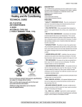
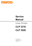
295421-YTG-B-0707
DESCRIPTION
This fan coil unit provides the flexibility for installation in any
upflow or horizontal application. These versatile models may
be used for split-system cooling or heat pump operation.
Compact cabinets along with return air options in both the
upflow and horizontal positions allow this unit to fit into tight
spaces such as attics, crawl spaces, and closets.
NOTE: For matching condensing units and performance
data, refer to condenser technical guides.
FEATURES
TECHNICAL GUIDE
SINGLE PIECE AIR HANDLERS
FOR USE WITH SPLIT-SYSTEM
COOLING & HEAT PUMPS
HEAT PUMP MODELS:
F*FP
VARIABLE SPEED MODEL:
F*FV
CABINET -The compact and sturdy cabinet is protected with
a durable, attractive finish to prevent rust. The cabinet is also
insulated to prevent cabinet sweating. F*FP and F*FV models have 3/4 inch insulation.
BLOWERS - Blowers are sized to circulate air both quietly
and efficiently. The direct-drive, multi-speed motors provide a
selection of air volume to match any application. Motor
speeds may be selected via quick connect terminal at the
motor. Slide-out blower/motor assemblies provide for easy
servicing.
COILS - Using the latest in heat transfer technology, the rifled
tube coil/aluminum fin coils produce high performance ratings
and provide long lasting quality. The coils are capable of bottom return air in the upflow position, and right or left end
return air in the horizontal position.
FACTORY INSTALLED TXV - Air handler models F*FP and
F*FV have factory installed TXV metering device.
ELECTRIC HEATERS - Models providing up to 25kw of heat
are available as field installed accessories. Electric heaters
are available in both single and three phase.
EASY INSTALLATION - These fan coil units are designed to
provide the lowest total installation cost. Accessible color
coded control wiring, top and side power wiring knockouts,
easy to install drain connections and electric heaters all combine to minimize installed cost on every job.
CONTROL BOARD - The control board is equipped with low
voltage terminal strips for easy installation. The control board
is also equipped with plug-in receptacles for the auxiliary
heaters.
ISO 9001
Certified Quality
Management System
Due to continuous product improvement, specifications
are subject to change without notice.
Visit us on the web at www.york.com
Additional rating information can be found at
www.ari.org/aridirectory.
FOR DISTRIBUTION USE ONLY - NOT TO BE USED AT POINT OF RETAIL SALE
295421-YTG-B-0707
DIMENSIONS
SHIPPING BRACKET*
REMOVE PRIOR TO
INSTALLATION (2 SCREWS)
ALL DIMENSIONS ARE IN INCHES. THEY ARE SUBJECT TO CHANGE
WITHOUT NOTICE. CERTIFIED DIMENSIONS WILL BE PROVIDED
UPON REQUEST.
F
10-3/8
J
F
3/4
4-1/8
DRAIN CONNECTIONS
FOR HORIZONTAL
APPLICATIONS
10-3/8
K
7-1/2
TOP VIEW (ALL MODELS)
A
4
=DRAIN PAN FOOTPRINT
MAX. FILTER LENGTH
(21 INCHES)
MAX. FILTER WIDTH
(B MINUS 1-1/2 INCHES)
VAPOR
OPENING
LIQUID
OPENING
3/4
D
REAR
3/4
C
2
18-3/8
B
E
DRAIN CONNECTIONS
FOR UPFLOW APPLICATIONS
FILTER
ACCESS
BOTTOM VIEW
Wiring K.O.s1
Dimensions
Model
A
B
C
Height
Width
Depth
F4FP024H06T2*
40-3/4
18
F4FP030H06T2*
40-3/4
18
F4FP036H06T2*
40-3/4
21-1/2
F4FP040H06T2*
40-3/4
21-1/2
D
12-1/8
E
F
14-7/8
16-1/2
14-7/8
16-1/2
18-3/8
20
18-3/8
20
F4FP042H06T2*
40-3/4
21-1/2
18-3/8
20
F4FP045H06T2*
50-3/4
24
20-7/8
22-1/2
F5FP048H06T2*
50-3/4
24
20-7/8
22-1/2
F5FP060H06T2*
50-3/4
24
20-7/8
22-1/2
F4FV060H06T2*
50-3/4
24
20-7/8
22-1/2
22
17-3/8
J
K
Power
Control
Refrigerant Connections
Line Size
Liquid
Vapor
5/8
3/4
7/8 (1/2)
1-3/8 (1)
3/4
7/8
7/8 (1/2)
3/8
7/8
7/8
7/8 (1/2)
1-3/8(1)
1-23/32
(1-1/4)
7/8
7/8
7/8
1. Actual conduit size is shown in parenthesis.
2. All models only available with factory installed horizontal drain pan.
2
Unitary Products Group
295421-YTG-B-0707
COIL TECHNICAL DATA
Models
Application
Coil
Slab Size
Refrigerant
Face
Fins
Deep
Connection
Area
Per
Rows
Type
(Sq. Ft.)
Inch
H
W
Tube
Geometry
Tube
Fin. Type
Dia.
Metering
Device
F4FP024H06T2A
A/C & HP
3.40
2
14
14
17.5
F4FP024H06T2B
A/C & HP
3.40
2
14
14
17.5
TXV-2A
TXV-2B
F4FP030H06T2A
A/C & HP
3.89
2
14
16
17.5
TXV-2A
F4FP036H06T2A
A/C & HP
3.40
3
12
14
17.5
TXV-2A
F4FP040H06T2A
A/C & HP
3.89
3
11
16
17.5
TXV-2A
F4FP040H06T2C
A/C & HP
3.89
3
11
16
17.5
TXV-2C
F4FP042H06T2A
A/C & HP
3.89
3
11
16
17.5
F4FP042H06T2C
A/C & HP
3.89
3
11
16
17.5
TXV-2C
F4FP045H06T2C
A/C & HP
5.83
3
12
24
17.5
TXV-2C
F5FP048H06T2C
A/C & HP
5.35
3
12
22
17.5
TXV-2C
F5FP060H06T2C
A/C & HP
5.83
3
12
24
17.5
TXV-2C
F4FV060H06T2C
A/C & HP
5.83
3
12
24
17.5
TXV-2C
Sweat
1 x .886
3/8
Enhanced
TXV-2A
COOLING CAPACITY
Blower
Model
Rated
CFM
Entering
Air °F
(Dry / Wet Bulb)
MBH @ Evaporator Temperature and Corresponding Pressure °F /
PSIG
35 / 61.5
40 / 68.5
45 / 76.0
50 / 84.0
Upflow / Horizontal Positions Only
F4FP024H06T2*
830
85 / 72
80 / 67
75 / 62
70 / 57
36.3
33.4
27.4
22.2
33.0
30.2
24.3
19.3
29.5
26.7
21.0
16.2
25.6
23.1
17.7
12.6
F4FP030H06T2*
1050
85 / 72
80 / 67
75 / 62
70 / 57
41.5
36.2
29.1
24.1
37.8
32.4
25.3
21.5
33.7
28.6
24.0
18.7
29.5
24.5
19.2
15.8
F4FP036H06T2*
1250
85 / 72
80 / 67
75 / 62
70 / 57
53.4
42.8
33.4
28.7
48.6
37.8
28.1
26.5
43.4
33.1
30.6
24.5
38.3
28.2
22.8
22.8
F4FP040H06T2*
1050
85 / 72
80 / 67
75 / 62
70 / 57
55.3
44.2
34.5
29.6
47.5
37.1
27.5
26.0
39.6
30.2
22.4
22.4
31.2
23.1
18.7
18.7
F4FP042H06T2*
1400
85 / 72
80 / 67
75 / 62
70 / 57
88.4
70.8
55.2
47.4
76.0
59.4
43.9
41.5
63.3
48.4
35.8
35.8
50.0
37.0
29.9
29.9
F4FP045H06T2*
1400
85 / 72
80 / 67
75 / 62
70 / 57
92.7
74.2
57.8
49.7
78.1
61.3
45.3
42.8
63.4
48.4
35.7
35.7
48.1
35.4
28.6
28.6
F5FP048H06T2*
1600
85 / 72
80 / 67
75 / 62
70 / 57
100.5
80.4
62.7
53.9
86.4
67.5
49.9
47.2
72.0
55.0
40.7
40.7
56.8
42.1
34.0
34.0
F5FP060H06T2*
1850
85 / 72
80 / 67
75 / 62
70 / 57
119.9
96.0
74.8
64.3
101.0
79.2
58.6
55.4
82.0
62.6
46.2
46.2
62.2
45.8
37.0
37.0
F4FV060H06T2*
1980
85 / 72
80 / 67
75 / 62
70 / 57
122.0
98.1
76.9
66.4
103.1
81.3
60.7
57.5
84.1
64.7
50.3
48.3
64.3
47.9
39.1
39.1
Unitary Products Group
3
295421-YTG-B-0707
ACCESSORIES
LIMITATIONS
Refer to Price Manual for specific model numbers.
These units must be wired and installed in accordance with
all national and local safety codes. Voltage limits are as follows:
VERTICAL SUSPENSION KIT - The suspension kit is
designed to be used with all sizes of fan coil units whenever
the application requires vertical suspension of the unit.
ELECTRIC HEATERS - Models shown under Electrical Data
include sequencers and temperature dual limit switches for
safe, efficient operation. Circuit breakers are provided where
shown.
Normal Operating voltage Range1
187-253
1. Utilization range “A” in accordance with ARI Std. 110.
Air flow must be within the minimum and maximum limits
approved for electric heat, evaporator coils and outdoor units:
BOLT-ON THERMAL EXPANSION VALVE - TXV kits are
available for enhanced efficiency. These fan coil units have
factory installed TXV’s.
Entering Air Temperature Limits
Wet Bulb Temp. ºF
Dry Bulb Temp. ºF
Min.
Max.
Min.
Max.
57
72
65
95
EXTENDED AIRFLOW DATA1 FOR 230 VOLT - HEAT PUMP MODELS
Models
F4FP024H06T2*
F4FP030H06T2*
F4FP036H06T2*
F4FP040H06T2*
F4FP042H06T2*
F4FP045H06T2*
F5FP048H06T2*
F5FP060H06T2*
F4FV060H06T2*
Blower Motor
Speed
230 Volt
CFM @ External Static Pressure - IWC
0.10
0.20
0.30
0.40
0.50
0.60
0.70
0.80
0.90
1.00
High
950
910
865
835
775
730
662
590
502
400
Med
845
815
785
745
705
654
594
524
439
344
Low
650
630
605
575
540
508
450
383
285
158
High
1,270
1,210
1,150
1,085
1,015
946
862
769
645
502
Med
1,050
1,040
995
930
855
804
714
624
494
364
Low
855
820
780
735
680
624
550
447
333
190
High
-
1,310
1,250
1,175
1,120
1,053
983
894
779
645
Med
1,200
1,150
1,100
1,040
985
933
879
795
711
587
Low
1,060
1,015
970
925
860
809
740
661
572
453
High
1,270
1,210
1,150
1,085
1,015
946
802
769
645
502
Med
1,050
1,040
995
930
855
804
714
624
494
364
Low
855
820
780
735
680
624
550
447
333
190
High
-
1,575
1,500
1,420
1,350
1,273
1,192
1,102
996
871
Med
1,460
1,395
1,330
1,260
1,190
1,125
1,052
960
842
695
Low
1,250
1,200
1,155
1,100
1,050
1,001
931
851
751
631
High
1,575
1,535
1,475
1,390
1,310
1,245
1,147
1,030
897
735
Med High
1,375
1,315
1,255
1,185
1,110
1,040
944
848
732
606
Med Low
1,210
1,160
1,110
1,050
980
921
844
737
640
533
Low
1,035
990
940
890
825
770
698
616
524
432
High
2223
2158
2090
2029
1929
1861
1788
1679
1594
1501
Med High
1948
1904
1801
1815
1777
1741
1681
1618
1539
1453
Med
1741
1690
1649
1606
1564
1516
1476
1436
1387
1353
Med Low
1499
1454
1415
1370
1328
1269
1228
1191
1132
1093
Low
1286
1233
1177
1142
1092
1039
987
960
888
842
High
2195
2145
2070
2008
1920
1852
1754
1663
1570
1462
Med High
1938
1899
1873
1824
1791
1724
1679
1603
1521
1420
Med
1726
1681
1641
1607
1560
1517
1485
1433
1402
1349
Med Low
1525
1483
1441
1383
1356
1291
1253
1208
1169
1123
Low
1306
1254
1204
1160
1114
1061
1008
980
914
876
High
2,285
2,195
2,105
2,015
1,950
1,845
1,770
1,685
1,590
1,485
Med.
2,125
2,020
1,910
1,805
1,705
1,597
1,491
1,386
1,280
1,175
Low
1,655
1,605
1,550
1,500
1,450
1,398
1,326
1,245
1,153
1,052
NOTE: Air flow data shown above 0.50” W.C. external static pressure is for REFERENCE ONLY. Maximum allowable external static when electric heat is used is
limited to 0.50” W.C. Maximum allowable external static pressure may also be limited by minimum CFM requirements for proper Heat Pump operation.
1. Includes Return Air Filter and Largest Electric Heater.
All F*FP series air handler units are UL Listed up to 0.50" w.c. external static pressure, including air filter, wet coil, and largest KW size heater.
4
Unitary Products Group
295421-YTG-B-0707
EXTENDED AIR FLOW DATA1 FOR 208 VOLT - HEAT PUMP MODELS
208 Volt
Models
Blower Motor
Speed
F4FP024H06T2*
F4FP030H06T2*
F4FP036H06T2*
F4FP040H06T2*
F4FP042H06T2*
F4FP045H06T2*
CFM @ External Static Pressure - IWC
0.10
0.20
0.30
0.40
0.50
0.60
0.70
0.80
0.90
1.00
High
855
819
779
752
698
657
596
531
452
360
Med.
760
733
706
670
634
589
535
472
395
310
Low
585
567
545
518
486
457
405
344
257
142
High
1143
1089
1035
977
914
851
776
692
581
451
Med.
941
936
895
837
770
724
643
562
445
328
Low
770
738
702
662
612
561
495
402
300
171
High
1235
1179
1125
1058
1008
947
885
804
701
580
Med.
1080
1035
990
936
887
840
791
716
640
528
Low
954
914
873
833
774
728
666
595
515
408
High
1143
1089
1035
977
914
851
776
692
581
451
Med.
941
936
895
837
770
724
643
562
445
328
Low
770
738
702
662
612
561
495
402
300
171
High
1400
1418
1350
1278
1215
1145
1073
991
897
784
Med.
1314
1266
1197
1135
1071
1012
947
864
758
625
Low
1125
1080
1040
990
945
901
838
766
676
568
High
1418
1382
1328
1251
1179
1120
1032
927
807
661
Med-high
1238
1184
1130
1067
999
936
850
763
659
545
Med-low
1089
1044
999
945
882
829
760
663
576
480
Low
932
891
846
801
743
693
628
554
472
389
High
2209
2140
2093
2000
1939
1864
1746
1724
1655
1587
Med High
1945
1906
1871
1819
1784
1741
1667
1640
1595
1550
Med
1739
1690
1640
1602
1559
1516
1470
1431
1387
1343
Med Low
1506
1464
1415
1369
1325
1283
1238
1193
1139
1100
F5FP048H06T2*
Low
1301
1248
1197
1151
1095
1054
1005
958
909
860
High
2134
2124
2052
1979
1861
1756
1639
1597
1512
1427
Med High
1916
1875
1838
1777
1744
1671
1594
1584
1537
1490
Med
1716
1671
1613
1569
1523
1475
1429
1384
1337
1290
Med Low
1494
1435
1390
1341
1284
1241
1194
1139
1087
1036
Low
1276
1223
1168
1115
1068
1009
965
902
847
792
High
2057
1976
1895
1814
1728
1661
1593
1517
1431
1337
Med.
1913
1818
1719
1625
1535
1437
1342
1247
1152
1057
Low
1490
1445
1395
1350
1305
1258
1194
1120
1038
946
F5FP060H06T2*
F4FV060H06T2*
NOTE: Air flow data shown above 0.50” W.C. external static pressure is for REFERENCE ONLY. Maximum allowable external static when electric heat is used is
limited to 0.50” W.C. Maximum allowable external static pressure may also be limited by minimum CFM requirements for proper Heat Pump operation.
1. Includes Return Air Filter and Largest Electric Heater.
All F*FP series air handler units are UL Listed up to 0.50" w.c. external static pressure, including air filter, wet coil, and largest KW size heater.
APPLICATION FACTORS-RELATED CFM VS. ACTUAL CFM
% Of Rated Airflow
80%
90%
RATED CFM
110%
120%
Capacity Factor
0.96
0.98
1.00
1.02
1.03
Unitary Products Group
5
295421-YTG-B-0707
EXTENDED AIR FLOW DATA - F4FV VARIABLE SPEED MODELS
CFM/TAP SELECTION - F4FV1
DELAY PROFILE
High Speed
Cooling and
Heat Pump CFM
"DELAY" Tap
Comfort Setting
Model
Jumper
Setting
A
Normal
F4FV060H06T2*
"COOL” TAP
“ADJ TAP“
B
Humid
2100
“A”
“B"
C
Dry
1980
"B”
"B"
D
Temperate
1860
"A”
"A"
1750
"B”
"A"
1675
"A”
"C"
1605
"C”
"B"
1575
"B”
"C"
1510
"D”
"B"
1420
"C”
"A"
1335
"D”
"A"
1280
"C”
"C"
1200
"D”
“C”
NOTE:
1. Both the “COOL” and the “ADJ” tap must be set for the cooling CFM.
2. Fan only CFM = 63% of high speed cooling.
3. Low speed cooling used only with two stage outdoor units.
(Speed is preset to 65% of high speed).
4. Dehumidification speed is 85% of cooling speed.
5. When operating in both heat pump and electric heat modes, the CFM will
be whichever is greater.
6. CFM indicator light flashes once for every 100 CFM (i.e., 12 Flashes is
1200 CFM).
ELECTRIC HEAT CFM
Model
F4FV060H06T2*
6
CFM
Tap Selections
–
"HEAT"
1860
"A"
1750
"B"
1420
"C"
1335
"D"
Normal
The normal setting provides a 30-second ramp-up from zero
airflow to full capacity and a 30-second ramp-down from full
capacity back to zero airflow. Whenever there is a change in
airflow mode, such as a call for cooling or a change from low
heat to high heat, the motor will take 30 seconds to ramp
from one speed to the other.
Humid
The humid setting is best-suited for installations where the
humidity is frequently very high during cooling season, such
as in the southern part of the country. On a call for cooling,
the blower will ramp up to 50% of full capacity and will stay
there for two minutes, then will ramp up to 82% of full capacity and will stay there for five minutes, and then will ramp up
to full capacity, where it will stay until the wall thermostat is
satisfied. In every case, it will take the motor 30 seconds to
ramp from one speed to another.
Dry
The dry setting is best suited to parts of the country where
excessive humidity is not generally a problem, where the
summer months are usually dry. On a call for cooling the
motor will ramp up to full capacity and will stay there until the
thermostat is satisfied. At the end of the cooling cycle, the
blower will ramp down to 50% of full capacity where it will stay
for 60 seconds. Then it will ramp down to zero. In every case,
it will take the motor 30 seconds to ramp from one speed to
another.
Temperate
The temperate setting is best suited for most of the country,
where neither excessive humidity nor extremely dry conditions are the norm. On a call for cooling, the motor will ramp
up to 63% of full capacity and will stay there for 90 seconds,
then will ramp up to full capacity. At the end of the cooling
cycle, the motor will ramp down to 63% of full capacity and
will stay there for 30 seconds, then will ramp down to zero. In
every case, it will take the motor 30 seconds to ramp from
one speed to another.
Unitary Products Group
295421-YTG-B-0707
Physical and Electrical Data
MODEL
F4FP024H06T2* F4FP030H06T2* F4FP036H06T2* F4FP040H06T2*
Blower - Diameter Width
10x6
HP
Motor
10x8
10x8
–
10x8
–
1/4
1/3
1/2
1/3
–
1075
1075
1075
1075
–
Full Load
1.6/1.4
2.5/2.2
3.3/2.9
2.5/2.2
–
Locked Rotor
3.3/2.9
6.2/5.5
7.4/6.5
6.2/5.5
–
–
Nominal RPM
Voltage
208/230
AMPS
Type
Filter1
Disposable/Permanent
Size
Permanent Type Kit
16x20x1
16x20x1
20x20x1
20x20x1
1PF0601BK
1PF0601BK
1PF0602BK
1PF0601BK
–
98/93
105/100
115/109
121/115
–
Shipping/Operating Weight (lbs.)
MODEL
F4FP042H06T2* F4FP045H06T2* F5FP048H06T2* F5FP060H06T2* F4FV060H06T2*
Blower - Diameter x Width
10x8
10x10
11x10
11x10
3/4
1/3
1.0
1.0
1.0
1130
925
1050
1050
1200
4.4/3.8
3.0/2.7
7.6
7.6
7.8/7.0
11.9/10.3
4.8/4.1
–
–
–
HP
Motor
Nominal RPM
Voltage
208/230
Full Load
Amps
Locked Rotor
230
Type
Filter1
11x10
Disposable/Permanent
Size
Permanent Type Kit
20x20x1
22x20x1
22x20x1
22x20x1
22x20x1
1PF0602BK
1PF0603BK
1PF0603BK
1PF0603BK
1PF0603BK
121/115
150/144
153/147
160/154
160/154
Shipping/Operating Weight (lbs.)
1. Field Supplied.
ELECTRICAL DATA - Cooling Only
Models
Total Motor Amps
Minimum Circuit
ampacity
Max. O.C.P.1 Amps/
Type
Minimum Wire
Size A.W.G.
208V
240V
208V
240V
F4FP024H06T2*
1.6
1.5
2.0
1.8
15
14
F4FP030H06T2*
2.5
2.3
3.2
2.8
15
14
F4FP036H06T2*
3.3
3.0
4.2
3.7
15
14
F4FP040H06T2*
2.5
2.3
3.2
2.8
15
14
F4FP042H06T2*
4.4
4.0
5.5
4.8
15
14
F4FP045H06T2*
3.1
2.6
3.9
3.4
15
14
F5FP048H06T2*
7.6
7.6
9.5
9.5
15
14
F5FP060H06T2*
7.6
7.6
9.5
9.5
15
14
–
–
–
–
15
14
VARIABLE SPEED MODEL
F4FV060H06T2*
1. O.C.P. = Over Current Protection device, must be HACR type Circuit Breaker or Time Delay Fuse.
Unitary Products Group
7
295421-YTG-B-0707
ELECTRICAL DATA - 1∅ - 208/230 - 1-60
Heater1
Model
Models
Static
F4FP030H06T2*
F4FP040H06T2*
F4FP045H06T2*
F5FP060H06T2*
F4FV060H06T2*
W2 Only
W1 + W2
208V
240V
208V
240V
208V
240V
208V
Low
3.8
5.0
13.0
17.1
3.8
5.0
3.8
5.0
3.8
5.0
Low
5.6
7.5
19.1
25.6
3.8
5.0
5.6
7.5
5.6
7.5
2HK*6501006B
Low
7.5
10.0
25.6
34.1
3.8
5.0
7.5
10.0
7.5
10.0
2HK*6500506B
Low
3.8
5.0
13.0
17.1
3.8
5.0
3.8
5.0
3.8
5.0
2HK*6500806B
Low
5.6
7.5
19.1
25.6
3.8
5.0
5.6
7.5
5.6
7.5
2HK*6500806B
2HK*6501006B
0.5
0.5
240V
Low
7.5
10.0
25.6
34.1
3.8
5.0
7.5
10.0
7.5
10.0
High
11.3
15.0
38.6
51.2
3.8
5.0
7.5
10.0
11.3
15.0
2HK*6500506B
Low
3.8
5.0
13.0
17.1
3.8
5.0
3.8
5.0
3.8
5.0
2HK*6500806B
Low
5.6
7.5
19.1
25.6
3.8
5.0
5.6
7.5
5.6
7.5
Low
7.5
10.0
25.6
34.1
3.8
5.0
7.5
10.0
7.5
10.0
2HK16501506B
2HK*6501006B
Med
11.3
15.0
38.6
51.2
3.8
5.0
7.5
10.0
11.3
15.0
2HK16501906B4
High
13.2
17.6
45.1
60.1
2.8
3.8
10.4
13.8
13.2
17.6
2HK*6500506B
Low
3.8
5.0
13.0
17.1
3.8
5.0
3.8
5.0
3.8
5.0
2HK*6500806B
Low
5.6
7.5
19.1
25.6
3.8
5.0
5.6
7.5
5.6
7.5
2HK*6501006B
0.5
0.5
Low
7.5
10.0
25.6
34.1
3.8
5.0
7.5
10.0
7.5
10.0
High
11.3
15.0
38.6
51.2
3.8
5.0
7.5
10.0
11.3
15.0
2HK*6500506B
Low
3.8
5.0
13.0
17.1
3.8
5.0
3.8
5.0
3.8
5.0
2HK*6500806B
Low
5.6
7.5
19.1
25.6
3.8
5.0
5.6
7.5
5.6
7.5
2HK*6501006B
0.5
Low
7.5
10.0
25.6
34.1
3.8
5.0
7.5
10.0
7.5
10.0
2HK16501506B
Low
11.3
15.0
38.6
51.2
3.8
5.0
7.5
10.0
11.3
15.0
2HK*6500506B
Low
3.8
5.0
13.0
17.1
3.8
5.0
3.8
5.0
3.8
5.0
2HK*6500806B
Low
5.6
7.5
19.1
25.6
3.8
5.0
5.6
7.5
5.6
7.5
2HK*6501006B
0.5
2HK16501506B
F5FP048H06T2*
W1 Only
240V
2HK16501506B
F4FP042H06T2*
KW Staging3
MBH
208V
2HK16501506B
F4FP036H06T2*
KW
Tap
2HK*6500506B
F4FP024H06T2*
Total Heat2
MAX. STATIC
& MIN. CFM
Med
7.5
10.0
25.6
34.1
3.8
5.0
7.5
10.0
7.5
10.0
High
11.3
15.0
38.6
51.2
3.8
5.0
7.5
10.0
11.3
15.0
2HK16500506B
Med-Low
3.8
5.0
13.0
17.1
3.8
5.0
3.8
5.0
3.8
5.0
2HK16500806B
Med-Low
5.6
7.5
19.1
25.6
3.8
5.0
5.6
7.5
5.6
7.5
Med-Low
7.5
10.0
25.6
34.1
3.8
5.0
7.5
10.0
7.5
10.0
Med-Low
11.3
15.0
38.6
51.2
3.8
5.0
7.5
10.0
11.3
15.0
2HK16502006B
Med-Low
15.0
20.0
51.2
68.3
3.8
5.0
11.3
10.0
15.0
20.0
2HK16502506B
Med-Low
18.8
25.0
64.2
85.3
3.8
5.0
11.3
15.0
18.8
25.0
2HK*6501006B
Med
3.8
5.0
13.0
17.1
3.8
5.0
3.8
5.0
3.8
5.0
2HK16500806B
Med
5.6
7.5
19.1
25.6
3.8
5.0
5.6
7.5
5.6
7.5
2HK*6501006B
2HK16501506B
2HK16501006B
0.5
Med
7.5
10.0
25.6
34.1
3.8
5.0
7.5
10.0
7.5
10.0
Med
11.3
15.0
38.6
51.2
3.8
5.0
7.5
10.0
11.3
15.0
2HK16502006B
Med
15.0
20.0
51.2
68.3
3.8
5.0
7.5
10.0
15.0
20.0
2HK16502506B
Med
18.8
25.0
64.2
85.3
3.8
5.0
11.3
15.0
18.8
25.0
2HK*6500806B
1335
5.6
7.5
19.1
25.6
3.8
5.0
5.6
7.5
5.6
7.5
2HK*6501006B
1335
7.5
10.0
25.6
34.1
3.8
5.0
7.5
10.0
7.5
10.0
2HK16501506B
2HK16501506B
0.5
0.5
1335
11.3
15.0
38.6
51.2
3.8
5.0
7.5
10.0
11.3
15.0
2HK16502006B
1335
15.0
20.0
51.2
68.3
3.8
5.0
7.5
10.0
15.0
20.0
2HK16502506B
1335
18.8
25.0
64.2
85.3
3.8
5.0
11.3
15.0
18.8
25.0
NOTE: All models available with factory installed horizontal drain pan.
1.
2.
3.
4.
0 or as follows: 0 = No Breaker, 1 = Breaker.
See Conversion Table below:
If first stage heat or 66 is connected to W1, otherwise refer to this table.
2HK16501906B only applies to F4FP036 Model.
KW & MBH CONVERSIONS - FOR TOTAL POWER INPUT REQUIREMENT
FOR
8
230V
OPERATION MULTIPLY
240V
TABULATED KW & MBH BY
.918
Unitary Products Group
295421-YTG-B-0707
ELECTRICAL DATA - 1∅ (SINGLE SOURCE POWER SUPPLY) - COPPER WIRE
Field Wiring
Models
F4FP024H06T2*
F4FP030H06T2*
F4FP036H06T2*
Model1
Heater
Amps
240V
208V
240V
208V
240V
208V
240V
2HK*6500506B
20.8
24.7
27.7
25
30
10
10
2HK*6500806B
31.3
35.5
40.7
40
45
8
8
2HK*6501006B
41.7
46.9
53.7
50
60
8
6
Heater
F4FP042H06T2*
F4FP045H06T2*
F5FP048H06T2*
F5FP060H06T2*
F4FV060H06T2*
Max. O.C.P.2
Amps/Type
75°C Wire
Size - AWG
2HK*6500506B
20.8
25.8
28.7
30
30
10
10
2HK*6500806B
31.3
36.7
41.7
40
45
8
8
2HK*6501006B
41.7
48.1
54.7
50
60
8
6
2HK16501506B
62.5
70.9
80.8
80
90
4
3
2HK*6500506B
20.8
26.8
29.5
30
30
10
10
2HK*6500806B
31.3
37.7
42.6
40
45
8
8
2HK*6501006B
41.7
49.1
55.6
50
60
8
6
2HK16501506B
62.5
71.9
81.6
80
90
4
3
3
73.3
83.3
95.2
90
100
3
3
2HK*6500506B
20.8
25.8
28.7
30
30
10
10
2HK*6500806B
31.3
36.7
41.7
40
45
8
8
2HK*6501006B
41.7
48.1
54.7
50
60
8
6
2HK16501506B
62.5
70.9
80.8
80
90
4
3
2HK*6500506B
20.8
28.1
30.5
30
35
10
8
2HK*6500806B
31.3
38.9
43.6
40
45
8
8
2HK*6501006B
41.7
50.3
56.6
60
60
6
6
2HK16501506B
62.5
73.2
82.6
80
90
4
3
2HK*6500506B
20.8
26.6
29.3
30
30
10
10
2HK*6500806B
31.3
37.4
42.3
40
45
8
8
2HK*6501006B
41.7
48.8
55.3
50
60
8
6
2HK16501506B
62.5
71.7
81.4
80
90
4
3
2HK16500506B
20.8
32.8
35.6
35
40
8
8
2HK*6500806B
31.3
43.0
48.4
45
50
8
8
2HK*6501006B
41.7
55.3
61.5
60
70
6
4
2HK16501506B
62.5
77.3
87.8
80
90
4
3
2HK16502006B
83.3
101.0
113.8
110
125
2
1
2HK16502506B
104.2
124.3
139.9
125
150
1
1/0
2HK*6500506B
20.8
32.8
35.6
35
40
8
8
2HK*6500806B
31.3
42.9
48.3
45
50
8
8
2HK*6501006B
41.7
55.3
61.6
60
70
6
4
2HK16501506B
62.5
78.5
87.8
80
90
4
3
2HK16502006B
83.3
101.0
113.8
110
125
2
1
2HK16502506B
104.2
122.2
139.5
125
150
1
1/0
2HK*6500806B
31.3
43.8
47.8
45
50
8
8
2HK16501906B
F4FP040H06T2*
Min. Circuit
Ampacity
2HK*6501006B
41.7
55.2
60.8
60
70
6
4
2HK16501506B
62.5
78.0
86.9
80
90
4
3
2HK16502006B
83.3
100.3
112.9
110
125
2
1
2HK16502506B
104.2
123.1
139.0
125
150
1
1/0
1. 0 or 1 as follows: 0 = No Breaker, 1 = Breaker
2. OCP = Over Current Protection device, must be HACR type Circuit Breaker or Time Delay fuse.
3. 2HK16501906B only applies to F4FP036 Model.
Unitary Products Group
9
295421-YTG-B-0707
ELECTRICAL DATA - 1 Ø (MULTI-SOURCE POWER SUPPLY) - COPPER WIRE
Models
Heater Model
Min. Circuit Ampacity
Max. O.C.P.1 Amps/Type
Circuit
Circuit
1st
2nd
3rd
1st
75°C Wire Size - AWG
Circuit
2nd
3rd
1st
2nd
3rd
208/240V 208/240V 208/240V 208/240V 208/240V 208/240V 208/240V 208/240V 208/240V
F4FP030H06T2*
F4FP036H06T2*
2HK16501506B 25.8/28.7 45.1/52.1
—
30/30
50/60
—
10/10
8/6
—
2HK16501506B 26.8/29.5 45.1/52.1
—
30/30
50/60
—
10/10
8/6
—
2HK16501906B2 38.3/42.6 45.7/52.6
—
40/45
50/60
—
8/8
8/6
—
F4FP040H06T2*
2HK16501506B 25.8/28.7 45.1/52.1
—
30/30
50/60
—
10/10
8/6
—
F4FP042H06T2*
2HK16501506B 28.1/30.5 45.1/52.1
—
30/35
50/60
—
10/8
8/6
—
F4FP045H06T2*
2HK16501506B 26.6/29.3 45.1/52.1
—
30/30
50/60
—
10/10
8/6
—
2HK16501506B 32.8/35.6 45.1/52.1
—
35/40
50/60
—
8/8
8/6
—
2HK16502006B 55.3/61.6 45.1/52.1
—
F5FP048H06T2*
F5FP060H06T2*
F4FV060H06T2*
60/70
50/60
—
6/4
8/6
—
2HK16502506B 32.8/35.6 45.1/52.1 45.1/52.1
35/40
50/60
50/60
8/8
8/6
8/6
2HK16501506B 32.8/35.6 45.1/52.1
—
35/40
50/60
—
8/8
8/6
—
2HK16502006B 55.3/61.6 45.1/52.1
—
60/70
50/60
—
6/4
8/6
—
2HK16502506B 33.8/35.6 45.1/52.1 45.1/52.1
35/40
50/60
50/60
8/8
8/6
8/6
2HK16501506B 33.0/34.8 45.1/52.1
—
35/35
50/60
—
8/8
8/6
—
2HK16502006B 55.2/60.8 45.1/52.1
—
60/70
50/60
—
6/4
8/6
—
35/35
50/60
50/60
8/8
8/6
8/6
2HK16502506B 33.0/34.8 45.1/52.1 45.1/52.1
1. OCP = Over Current Protection device, must be HACR type Circuit Breaker or Time Delay fuse.
2. 2HK16501906B only applies to F4FP036 Model.
ELECTRICAL DATA - 3∅ - 208/230-3-60
Models
Heater Model
F4FP024H06T2*
F4FP030H06T2*
F4FP036H06T2*
F4FP040H06T2*
F4FP042H06T2*
F4FP045H06T2*
F5FP048H06T2*
F5FP060H06T2*
F4FV060H06T2*
Total Heat1
MAX. STATIC
& MIN. CFM
KW
KW Staging2
MBH
W1 Only
W2 Only
W1 + W2
Static
Tap
208V
240V
208V
240V
208V
240V
208V
240V
208V
2HK06501025B
0.5
Low
7.5
10.0
25.6
34.1
3.8
5.0
7.5
5.0
7.5
240V
10.0
2HK06501025B
0.5
Low
7.5
10.0
25.6
34.1
3.8
5.0
7.5
5.0
7.5
10.0
2HK06501525B
0.5
High
11.3
15.0
38.6
51.2
3.8
5.0
7.5
10.0
11.3
15.0
2HK06501025B
0.5
Low
7.5
10.0
25.6
34.1
3.8
5.0
7.5
5.0
7.5
10.0
2HK06501525B
0.5
High
11.3
15.0
38.6
51.2
3.8
5.0
7.5
10.0
11.3
15.0
2HK06501025B
0.5
Low
7.5
10.0
25.6
34.1
3.8
5.0
7.5
5.0
7.5
10.0
2HK06501525B
0.5
High
11.3
15.0
38.6
51.2
3.8
5.0
7.5
10.0
11.3
15.0
2HK06501025B
0.5
Low
7.5
10.0
25.6
34.1
3.8
5.0
7.5
5.0
7.5
10.0
2HK06501525B
0.5
Low
11.3
15.0
38.6
51.2
3.8
5.0
7.5
10.0
11.3
15.0
2HK06501025B
0.5
Med
7.5
10.0
25.6
34.1
3.8
5.0
7.5
5.0
7.5
10.0
2HK06501525B
0.5
High
11.3
15.0
38.6
51.2
3.8
5.0
7.5
10.0
11.3
15.0
2HK06501025B
0.5
Med Low
7.5
10.0
25.6
34.1
3.8
5.0
7.5
5.0
7.5
10.0
2HK06501525B
0.5
Med Low
11.3
15.0
38.6
51.2
3.8
5.0
7.5
10.0
11.3
15.0
2HK06501025B
0.5
Med
7.5
10.0
25.6
34.1
3.8
5.0
7.5
5.0
7.5
10.0
2HK06501525B
0.5
Med
11.3
15.0
38.6
51.2
3.8
5.0
7.5
10.0
11.3
15.0
2HK06501025B
0.5
1335
7.5
10.0
25.6
34.1
3.8
5.0
7.5
10.0
7.5
10.0
2HK06501525B
0.5
1335
11.3
15.0
38.8
51.2
3.8
5.0
7.5
10.0
11.3
15.0
1. See Conversion Table below.
2. If first stage heat is connected to W1/66, otherwise refer to Table below.
KW & MBH CONVERSIONS - FOR TOTAL POWER INPUT REQUIREMENT
FOR
10
230V
OPERATION MULTIPLY
240V
TABULATED KW & MBH BY
.918
Unitary Products Group
295421-YTG-B-0707
ELECTRICAL DATA - 3∅ - (SINGLE SOURCE POWERSUPPLY) - COPPER WIRE
Field Wiring
Models
Heater Models
Min. Circuit Ampacity
208V
F4FP024H06T2*
F4FP030H06T2*
F4FP036H06T2*
F4FP040H06T2*
F4FP042H06T2*
F4FP045H06T2*
F5FP048H06T2*
F5FP060H06T2*
F4FV060H06T2*
240V
Max. O.C.P.1 Amps
208V
75°C Wire Size - AWG
240V
208V
240V
2HK06501025B
41.2
46.5
45
50
8
8
2HK06501025B
42.2
47.4
45
50
8
8
2HK06501525B
42.2
47.4
45
50
8
8
2HK06501025B
43.1
48.2
45
50
8
8
2HK06501525B
43.1
48.2
45
50
8
8
2HK06501025B
42.2
47.4
45
50
8
8
2HK06501525B
42.2
47.4
45
50
8
8
2HK06501025B
44.2
49.1
45
50
8
8
2HK06501525B
44.2
49.1
45
50
8
8
2HK06501025B
42.8
47.9
45
50
8
8
2HK06501525B
42.8
47.9
45
50
8
8
2HK06501025B
48.3
53.9
50
60
8
6
2HK06501525B
48.3
53.9
50
60
8
6
2HK06501025B
48.3
53.9
50
60
8
6
2HK06501525B
48.3
53.9
50
60
8
6
2HK06501025B
48.6
52.9
50
60
8
6
2HK06501525B
48.6
52.9
50
60
8
6
1. O.C.P. = Over Current Protection device, must be HACR type Circuit Breaker or Time Delay fuse.
FIELD WIRING CONNECTION - COOLING ONLY
OUTDOOR
UNIT
THERMOSTAT
FIELD WIRING CONNECTION - WITH HEATER KIT
OUTDOOR
UNIT
THERMOSTAT
R
R
Y
Y
G
G
W
W
FAN
COIL
UNIT
*
FAN
COIL
UNIT
R
Y
G W2 W1 O
C
R
Y
G W2 W1 O
C
* N OT REQUIRED ON 2 OR 5KW
Unitary Products Group
11
295421-YTG-B-0707
FIELD WIRING CONNECTIONS - COOLING MODELS WITH ELECTRIC HEAT WIRING
F* SERIES
F* SERIES
Air Handler Control Wiring
Typical A/C - Cooling only Applications
AIR HANDLER
BOARD
THERMOSTAT
R
Air Handler Control Wiring
Typical A/C with Electric Heat Applications
1 - STAGE
AIR CONDITIONING
R
Y
Y
G
G
W1
W1
W2
C
THERMOSTAT
R
Y
Y
G
W1
W1
W2
W2
W2
O
C
O
HUMIDISTAT 1
C
C
HUM
X
Y1
Y2
1 - STAGE
AIR CONDITIONING
R
G
Y
C
CFM selection
board only on
F4FV model
AIR HANDLER
BOARD
Y
Field
Installed
Jumper If Required
HUMIDISTAT 1
C
HUM
1
NOTE:
Dehumidification
control connection
(”Humidistat” jumper on
CFM selection board
tb
d)
CFM selection
board only on
F4FV model
X
Y1
Y2
1
NOTE:
Dehumidification
control connection
(”Humidistat” jumper on
CFM selection board
tb
d)
FIELD WIRING CONNECTIONS - SINGLE STAGE HEAT PUMP
THERMOSTAT
AIR HANDLER
BOARD
HEAT PUMP
R
R
R
Y
Y
Y
G
G
W1 Out
E
W1
W2
W2
O
O
O
C
C
C
L
X/L
W1
W
CFM selection board
only on F4FV model
HUM
HUMIDISTAT 1
X
Y1
Y2
1 NOTE:
Dehumidification control connection
(”Humidistat” jumper on CFM selection
board must be removed)
NOTES:
1. “Y” Terminal on Air Handler Control Board must be connected for full CFM and applications requiring 60 second Blower Off Delay
for SEER enhancement.
2. 1Optional Dehumidification Humidistat contacts open on rise.
3. For F4FV model - Remove Humidistat Jumper on CFM Selection Board - if used.
4. For F4FV model - For Heat Pump Applications - Remove Heat Pump Jumper on CFM Selection Board.
5. To change quantity of heat during HP defrost cycle - Reverse connections at W1 and W2 on Air Handler Control Board.
12
Unitary Products Group
295421-YTG-B-0707
TYPICAL INSTALLATION
POWER WIRING
TO MAIN
POWER SOURCE
SUPPLY
AIR
POWER WIRING
CONTROL
WIRING
REFRIGERANT
LINES
THERMOSTAT
TO
CONDENSATE
DRAIN
FILTER
ACCESS
LOUVERED
ELECTRIC HOT WATER HEATER
(Must comply with water heater installation instructions)
TYPICAL APPLICATIONS
UPFLOW
HORIZONTAL
RIGHT HAND APPLICATION
LEFT HAND APPLICATION
Unitary Products Group
13
295421-YTG-B-0707
NOTES
14
Unitary Products Group
295421-YTG-B-0707
NOTES
Unitary Products Group
15
NOTES
Subject to change without notice. Printed in U.S.A.
Copyright © by York International Corp. 2007. All rights reserved.
Unitary
Products
Group
295421-YTG-B-0707
Supersedes: 295421-YTG-A-0507
5005
York
Drive
Norman
OK
73069