Transcript
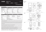
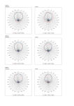
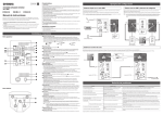
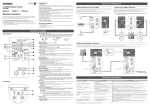
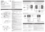
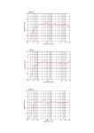
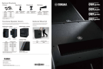
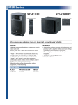
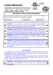
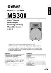
ZJ41650
EN
Controls and Connectors
DE
Installation Examples
Rear
SPEAKER SYSTEM
CAUTION
CBR series
Owner’s Manual
Pullback point (M8 screw hole)
(only for CBR15 and CBR12)
English
In order to take full advantage of the CBR series’ (referred to in this manual as CBR) superior functionality
and enjoy years of trouble-free use, please read this manual before you begin using the product.
After you have read the manual, keep it in a safe place for reference when needed.
Phone jack
• This manual uses example illustrations taken from the CBR12 if not otherwise specified.
• The illustrations as shown in this manual are for instructional purposes only.
• The company names and product names used in this manual are the trademarks or registered
trademarks of their respective companies.
speakON plug
• High-quality speaker unit, with smooth directional characteristics, and ports reducing wind roar in order
to achieve High-resolution sound quality
• High sound pressure thanks to the unit’s high-input tolerance and exceptional reliability from protection
circuitry
• Highly portable light and compact cabinet
• Input connectors supporting both speakON and phone plugs
• Installable with eye bolt rigging and brackets
Always follow the basic precautions listed below
to avoid the possibility of physical injury to you or
others, or damage to the device or other property.
These precautions include, but are not limited to, the
following:
Location
•Do not place the device in an unstable position or fail
to secure it properly in a potentially dangerous position
where it may fall even if the position is horizontal. The
device may accidentally fall over, resulting in damage
and/or injury.
•Do not use the speaker’s handles for suspended
installation. Doing so can result in damage or injury.
•Do not hold the bottom of the device when transporting
or moving it. In doing so, you may pinch your hands
under the device, and result in injury.
•Do not place the device in a location where it may come
into contact with corrosive gases or salt air. Doing so
may result in malfunction.
•Before moving the device, remove all connected cables.
•Always consult qualified Yamaha service personnel if
the device installation requires construction work, and
make sure to observe the following precautions.
–Choose mounting hardware and an installation
location that can support the weight of the device.
–Avoid locations that are exposed to constant vibration.
–Use the required tools to install the device.
–Inspect the device periodically.
Connections
•Before connecting the device to other devices, turn off
the power for all devices. Before turning the power on or
off for all devices, set all volume levels to minimum.
•Use only speaker cables. Use of other types of cables
may result in fire.
Handling caution
•Do not insert your fingers or hands in any gaps or
openings on the device.
•Do not rest your weight on the device or place heavy
objects on it, and avoid use excessive force on the
buttons, switches or connectors.
•Do not use the speakers for a long period of time at
a high or uncomfortable volume level, since this can
cause permanent hearing loss. If you experience any
hearing loss or ringing in the ears, consult a physician.
•Do not operate the device if the sound is distorting.
Prolonged use in this condition could cause overheating
and result in fire.
BWS251-300
8°
11°
20°
• Insert the screw or eye bolt through the
washer to attach them.
Upper rear of the unit
Apply thread-locking
fluid to the eye bolt
Pullback point
(M8 screw hole)
Installation using eye bolts
Attach commercially-available eye bolts (M8 x 15 mm) to the screw holes located at the bottom (two
locations) and on the upper rear (one location, only for CBR15 and CBR12). Keep in mind that you will
need two points at the bottom to suspend the unit.
CAUTION
Make sure to use eye bolts according to the standards and safety regulations in your area.
The tilt angle depends on the position relation between the speaker
and the wall. The maximum downward tilt angle is shown in the
following chart.
Maximum tilt angle
CBR15
CBR12
CBR10
Securing the screws and eye
bolts
M8 eye bolt
BWS251-400
17.5°
23°
35°
(Pullback point for
CBR15 and CBR12 only)
Max. 45°
Note
Use cables specially designed for speakers.
Using cables for musical instruments could cause
overheating and result in fire.
Maximum tilt
angle
❚❚NOTICE
The strength of an eye bolt differs depending on the suspension angle. Make sure to use eye bolts within
a range of 0 to 45 degrees from a right angle (as shown).
❚❚Using the BCS251 ceiling bracket
Bottom
PRECAUTIONS
CAUTION
❚❚Using the BWS251-300 or BWS251-400 wall mounting bracket
The phone jacks and the speakON connectors
are provided for connection to power amplifiers
or powered mixers, etc. with speaker cables.
• Technical Specifications (English only): includes specifications, block diagram, and dimensions.
• Owner’s Manual (this leaflet)
WARNING
Attach the bracket to two screw holes at the bottom of the unit using commercially available screws
(M8 x 16 mm) or eye bolts (M8 x 15 mm). For details on installing the bracket, refer to the corresponding
manual.
Turn to lock
Included Accessories
Always follow the basic precautions listed below to
avoid the possibility of serious injury or even death
from electrical shock, short-circuiting, damages, fire or
other hazards. These precautions include, but are not
limited to, the following:
Do not open
•This device contains no user-serviceable parts. Do not
open the device or attempt to disassemble the internal
parts or modify them in any way. If it should appear
to be malfunctioning, discontinue use immediately
and have it inspected by qualified Yamaha service
personnel.
Fire warning
•Do not put burning items, such as candles, on the unit.
A burning item may fall over and cause a fire.
• When the unit is shipped from the factory, a seal is
stuck on the pullback point (screw hole). Make sure to
peel off the seal when using the pullback point.
• The CBR10 does not have a pullback point.
Yamaha cannot be held responsible for damage or injury caused by insufficient strength of the support
structure or improper installation.
Installation using separately sold Yamaha speaker
brackets
Phone plug
Features
Please keep this manual in a safe place for future
reference.
Pullback point (only for CBR15 and CBR12)
speakON connector (compatible with
Neutrik NL4)
Auf der Rückseite befindet sich die deutsche Version der Bedienungsanleitung.
PLEASE READ CAREFULLY BEFORE
PROCEEDING
• Before doing any installation or construction work, consult with your Yamaha dealer.
• For optimum safety, the installation should be checked thoroughly at regular intervals. Some fittings may deteriorate over
extended periods of time due to wear and/or corrosion.
• When choosing the installation location, suspension wire and mounting hardware, make sure all are strong enough to
support the weight of the speaker.
• Make sure to take measures to prevent the speaker from falling down in the event of a installation failure.
• When installing the safety wire to the wall, install it higher than the wire’s attachment point on the speaker, with as little
slack as possible. If the wire is too long, and the speaker happens to fall, the wire may snap as a result of too much strain.
Correct:
Within 45° from a right angle
Max. 45°
0°
•When choosing a power amplifier for use with this
device, make sure that the output power of the amplifier
is lower than the power capacity of this device. If
the output power is higher than the power capacity,
malfunction or fire may occur.
•Do not input excessively loud signals that may result in
clipping in the amplifier or cause the following:
–Feedback, when using a microphone
–Continuous and extremely loud sound from a musical
instrument, etc.
–Continuous and extremely loud distorted sound
–Noise caused by plugging/unplugging the cable while
the amplifier is turned on
Even if the output power of the amplifier is lower than
the power capacity of this device (program), damage to
the device, malfunction or fire may occur.
923
235
45°
(Pullback point for CBR15
and CBR12 only)
Screw holes (M8)
Use these M8 size screw holes for installing
separately sold brackets or commercially
available eye bolts.
Pole socket
This socket adapts to commercially
available speaker stands and speaker
poles of 35 mm diameter.
Yamaha cannot be held responsible for damage caused
by improper use or modifications to the device, or data
that is lost or destroyed.
Max. 45°
Incorrect: Do not suspend the eye bolts as shown in the illustrations below.
❚❚Using the BBS251 baton bracket
Baton diameter
f 34 - f 51
923
235
(PA-4)
NOTICE
To avoid the possibility of malfunction/damage to the
product, damage to data, or damage to other property,
follow the notices below.
Handling and Maintenance
•Do not expose the device to excessive dust or vibration,
or extreme cold or heat (such as in direct sunlight, near
a heater, or in a car during the day), in order to prevent
the possibility of panel disfiguration, unstable operation,
or damage to the internal components.
•Do not place vinyl, plastic or rubber objects on the
device, since this might discolor the panel.
•When cleaning the device, use a dry and soft cloth.
Do not use paint thinners, solvents, cleaning fluids, or
chemical-impregnated wiping cloths.
•Condensation can occur in the device due to rapid,
drastic changes in ambient temperature—when the
device is moved from one location to another, or air
conditioning is turned on or off, for example. Using
the device while condensation is present can cause
damage. If there is reason to believe that condensation
might have occurred, leave the device for several hours
until the condensation has completely dried out.
•When turning on the AC power in your audio system,
always turn on the power amplifier LAST, to avoid
speaker damage. When turning the power off, the
power amplifier should be turned off FIRST for the same
reason.
•Be sure to observe the power amplifier’s rated load
impedance, particularly when connecting speakers in
parallel. Connecting an impedance load outside the
amplifier’s rated range can damage the power amplifier.
•Protective Circuit
All full-range loudspeakers are fitted with a self-resetting
poly switch that protects the high-frequency driver from
damage caused by excessive power. If a loudspeaker
cabinet loses high-frequency output, immediately
remove power from the power amplifier and wait for two
to three minutes. This should be long enough to allow
the poly switch to reset. Reapply power and check
the performance of the high-frequency driver before
continuing, with the power reduced to a level that does
not cause the poly switch to interrupt the signal.
•Air blowing out of the bass reflex ports is normal, and
often occurs when the speaker is handling program
material with heavy bass content.
Connectors
•Use only Neutrik speakON plugs (NL4) for connecting
speakON connectors.
Connection
Wiring
More than 45° from a right angle
More than 45°
More than 45°
CAUTION
In order to prevent the unit from falling down, attach the safety wire as shown in the
illustration.
Make sure to wire the plugs as shown below.
❚❚Phone plug
❚❚Neutrik speakON plug (NL4)
2– (unconnected)
Troubleshooting
2+ (unconnected)
1+ :
1– :
Symptom
No sound.
Parallel connection of speakers
The signals of the phone jack and speakON connector are connected in parallel. The first CBR receives
the signal from an amplifier (such as a power amplifier, a powered mixer, etc.) with the phone jack or the
speakON connector, and routes the signal to the second CBR. When connecting CBRs in parallel, be sure to
check the load impedance the amplifier can drive. The nominal impedance of one CBR is eight ohms and the
total impedance of two parallel connected CBRs is four ohms. In this case, the amplifier must be able to drive
less than four ohm load impedance.
From
amplifier
Amplifier
Only one suspension point
Max. 45°
The first CBR
(Impedance: 8Ω)
The second CBR
(Impedance: 8Ω)
Invalid connection
L channel
Amplifier
The cable is not connected properly. • Connect the cable all the way in so that it is firmly
in place.
• If the speakON connector is used, connect to “1+”
and “1-” and turn the plug to be locked.
A microphone is directed toward the Aim the speaker away from the area where the
speaker.
microphone picks up sound.
The sound is amplified too much.
Lower the volume of input device and locate the
microphone more closely to the sound source.
The amplifier
shuts down.
The total impedance of the
speakers is less than the minimum
load impedance of the amplifier.
Example: More than two speakers
(eight ohms) are connected to a
power amplifier, the load impedance
of which is six ohms.
Check the minimum load impedance of the power
amplifier, and lower the number of speakers
connected in parallel not to be less than the
impedance.
High frequency
range is
attenuated.
The protection circuit is operating in Refer to “Protection circuit” in the NOTICE.
the HF unit.
If any specific problem should persist, however, please contact your Yamaha dealer.
Parallel connection (total impedance: 4Ω)
Do not connect the input from
the amplifier to both the phone
jack and the speakON connector
simultaneously. This creates a
dangerous short circuit.
Possible solution
Howling sound
is produced
(feedback).
or
To next CBR
Possible causes
General Specifications
and
R channel
CBR
System Type
Frequency Range (-10dB)
Coverage Angle
(Horizontal x Vertical)
Maximum SPL
(Calculated, 1m)
Crossover Frequency
Nominal Impedance
NOISE
Power Rating
PGM
(IEC noise)
MAX
Sensitivity (1W, 1m)
LF
Components
HF
CBR15
CBR12
2-way Speaker, Bass-reflex Type
46 Hz–20 kHz
48 Hz–20 kHz
CBR10
50 Hz–20 kHz
H90° x V60° Constant Directivity Horn
126 dB SPL
125 dB SPL
123 dB SPL
2.0 kHz
8Ω
250 W
500 W
1000 W
96 dB SPL
15" Cone, 2.5" Voice Coil
2.1 kHz
8Ω
175 W
350 W
700 W
96 dB SPL
12" Cone, 2" Voice Coil
2.8 kHz
8Ω
175 W
350 W
700 W
94 dB SPL
10" Cone, 2" Voice Coil
1" Voice Coil,
Compression Driver
308 x 493 x 289 mm
(12.1" x 19.4" x 11.4")
9.4 kg (20.7 lbs)
Top x 1
1.4" Voice Coil, Compression Driver
Dimensions (WxHxD,
Including Rubber Feet)
Net Weight
Handles
455 x 700 x 378 mm
(17.9" x 27.6" x 14.9")
17.7 kg (39.0 lbs)
Side x 2
376 x 601 x 348 mm
(14.8" x 23.7" x 13.7")
13.9 kg (30.6 lbs)
Pole Socket
f35 mm, Bottom x 1
Rigging Points
Bottom x 2, Rear x 1 (Fit for M8 x 15 mm)
Bottom x 2
(Fit for M8 x 15 mm)
Optional Speaker Brackets BBS251, BCS251, BWS251-300, BWS251-400
Connectors
1/4" Phone x 1, speakON NL4MP x 1
*The contents of this manual apply to the latest specifications as of the printing date. Since Yamaha makes
continuous improvements to the product, this manual may not apply to the specifications of your particular
product. To obtain the latest manual, access the Yamaha website then download the manual file. Since
specifications, equipment or separately sold accessories may not be the same in every locale, please
check with your Yamaha dealer.