1
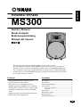
ENGLISH
POWERED SPEAKER
MS300
Owner’s Manual
Mode d’emploi
Bedienungsanleitung
Manual del Usuario
Thank you for purchasing the Yamaha MS300 powered speaker system.
The development of this powered bi-amplifier speaker system is a natural extension of
Yamaha’s extensive experience and knowledge of PA devices. The MS300 faithfully reproduces sound for a wide range of applications. Please read this owner’s manual thoroughly
to make the best use of the MS300 for the longest possible period of time. Keep the manual
in a safe place for future reference.
Features
Contents
• Lightweight, high-powered speaker with a
newly-developed 12-inch woofer
• The speaker uses an “EE Engine” based on
Yamaha’s proprietary amplifier drive technology
for high-efficiency drive. It features a high-output
bi-amplifier configuration (LF 225 W and HF
85 W).
• Optional speaker stand and installation brackets
available for various applications.
Precautions............................................................... 3
Rear Panel................................................................. 4
Connection Examples.............................................. 5
Specifications............................................................ 6
General specifications .............................................. 6
Amp.unit .................................................................. 6
Dimensions .............................................................. 6
Performance graph .................................................. 6
Block Diagram.......................................................... 6
Installation Examples............................................... 7
M
• Explanation of Graphical Symbols
CAUTION
RISK OF ELECTRIC SHOCK
DO NOT OPEN
CAUTION: TO REDUCE THE RISK OF
ELECTRIC SHOCK, DO NOT REMOVE
COVER (OR BACK). NO USER-SERVICEABLE
PARTS INSIDE. REFER SERVICING TO
QUALIFIED SERVICE PERSONNEL.
The above warning is located on the
rear of the unit.
WARNING: THIS APPARATUS MUST BE EARTHED
IMPORTANT
THE WIRES IN THIS MAINS LEAD ARE COLOURED IN
ACCORDANCE WITH THE FOLLOWING CODE:
GREEN-AND-YELLOW :
EARTH
BLUE :
NEUTRAL
BROWN :
LIVE
As the colours of the wires in the mains lead of this apparatus may
not correspond with the coloured markings identifying the terminals in
your plug, proceed as follows:
The wire which is coloured GREEN and YELLOW must be
connected to the terminal in the plug which is marked by the letter E
or by the safety earth symbol
or coloured GREEN and YELLOW.
The wire which is coloured BLUE must be connected to the terminal
which is marked with the letter N or coloured BLACK.
The wire which is coloured BROWN must be connected to the
terminal which is marked with the letter L or coloured RED.
* This applies only to products distributed by YAMAHA KEMBLE
MUSIC (U.K.) LTD.
2
The lightning flash with arrowhead symbol
within an equilateral triangle is intended to
alert the user to the presence of uninsulated
“dangerous voltage” within the product’s
enclosure that may be of sufficient magnitude to constitute a risk of electric shock to
persons.
The exclamation point within an equilateral triangle is intended to alert the user to
the presence of important operating and
maintenance (servicing) instructions in the
literature accompanying the product.
Precautions
• Use only the included power cord for this unit.
Using other types may be a fire and electrical shock
hazard.
• Do not allow water to enter this unit or allow the
unit to become wet. Fire or electrical shock may
result.
• Do not place a container with liquid or small metal
objects on top of this unit. Liquid or metal objects
inside this unit are a fire and electrical shock hazard.
• Connect the included power cord only to an AC
outlet of the type stated in this Owner’s Manual or
as marked on the unit. Failure to do so is a fire and
electrical shock hazard.
• Do not scratch, bend, twist, pull, or heat the power
cord. A damaged power cord is a fire and electrical
shock hazard.
• Do not place heavy objects, including this unit, on
top of the power cord. A damaged power cord is a
fire and electrical shock hazard. In particular, be
careful not to place heavy objects on a power cord
covered by a carpet.
• Place the device near a power outlet so you can easily plug it in.
• If you notice any abnormality, such as smoke, odor,
or noise, or if a foreign object or liquid gets inside
the unit, turn it off immediately. Remove the power
cord from the AC outlet. Consult your dealer for
repair. Using the unit in this condition is a fire and
electrical shock hazard.
• Should this unit be dropped or the cabinet be damaged, turn the power switch off, remove the power
plug from the AC outlet, and contact your dealer. If
you continue using the unit without heeding this
instruction, fire or electrical shock may result.
• If the power cord is damaged (i.e., cut or a bare wire
is exposed), ask your dealer for a replacement.
Using the unit with a damaged power cord is a fire
and electrical shock hazard.
• Do not remove the unit’s cover. You could receive an
electrical shock. If you think internal inspection,
maintenance, or repair is necessary, contact your
dealer.
• Do not modify the unit. Doing so is a fire and electrical shock hazard.
• If lightning begins to occur, turn off the power
switch of the unit as soon as possible, and unplug
the power cable plug from the electrical outlet.
• If there is a possibility of lightning, do not touch the
power cable plug if it is still connected. Doing so
may be an electrical shock hazard.
• Turn off all audio equipment, and speakers when
connecting to this unit. Use the correct connecting
cables and connect as specified.
• Always lower the volume control to minimum
before turning on the power to this unit. A sudden
blast of sound may damage your hearing.
• When rack-mounting the unit, allow enough free
space around the unit for normal ventilation. This
should be: 20 cm at the sides, 25 cm behind, and 30
cm above.
For normal ventilation during use, remove the rear
of the rack or open a ventilation hole.
If the airflow is not adequate, the unit will heat up
inside and may cause a fire.
• This unit is heavy. Use two or more people to carry
it.
• If you stack the speakers, secure the handles of the
speakers using a belt and fix the speakers to the floor
or wall to prevent them from falling and causing
injury. Do not stack more than two speakers.
• Do not use the handles to suspend the speaker. Otherwise, it may fall, causing injury.
• Hold the power cord plug when disconnecting it
from an AC outlet. Never pull the cord. A damaged
power cord is a potential fire and electrical shock
hazard.
• Do not touch the power plug with wet hands. Doing
so is a potential electrical shock hazard.
• XLR-type connectors are wired as follows: pin 1:
ground, pin 2: hot (+), and pin 3: cold (–).
• Using a mobile telephone near this unit may induce
noise. If noise occurs, use the telephone away from
the unit.
• Do not use the speakers at uncomfortably loud
level. Otherwise, you may damage your hearing.
3
Rear Panel
9
8
7
6
2
1
2
3
1
1
2
A POWER switch
This switch turns the power to the MS300 on and
off. When you turn this switch on, the POWER
indicator (8) lights up green.
B AC IN connector
Connect the included power cord here.
C LINE connectors
These balanced connectors accept input from
line-level sources, such as a mixer. The connectors include: an XLR-3-31 type; an XLR-3-32
type; a 1/4" TRS phone jack. They are all connected in parallel and can be used as line outputs.
In this case, input signals from the MIC connector (5) will not be output.
D LINE LEVEL control
This control enables you to adjust the level of signal input from the LINE connectors (3).
E MIC connector
Mic-level sources are input at this balanced,
XLR-3-31 type connector. The internal low-cut
filter will cut the range of these signals below
70 Hz. The mic input will not be routed to any
destination other than the speaker.
4
1
3
3
3
5
2
4
F MIC control
This control enables you to adjust the level of signal input at the MIC connector (5).
G MASTER LEVEL control
This control enables you to adjust the entire volume level.
H POWER indicator
When you turn the power on, this indicator lights
up green.
I EQ control
LOW: This EQ adjusts the low band in the range
of 0 ~ –8 dB with a center frequency of 55 Hz.
The 0 (MAX) setting is flat. Turn the control
couterclockwise to cut.
HIGH: This EQ adjusts the high band. The arrow
setting is flat. Turn the control clockwise to
boost and couterclockwise to cut the HF band
(1.6 kHz or higher) in the range of ±3 dB.
Connection Examples
Stereo setup
Without a mixer
2
1
2
3
1
1
2
3
3
1
3
2
1
2
1
2
3
3
1
3
2
1
2
1
3
3
2
LINE OUT
Microphone
CD player or tape deck
Mixer
Daisy chain
To the next speaker
2
1
2
3
2
2
1
2
2
1
2
2
1
3
2
1
1
3
3
1
3
3
1
3
2
3
1
1
3
3
1
To the next speaker
2
1
3
3
2
LINE OUT
Mixer
5
Specifications
■ General specifications
Controls
LEVEL ............... MASTER, MIC, LINE
EQ ....................... LOW: 0 (Max.) ~ –8 dB (Min.) at 55 Hz
HIGH: ±3 dB (HF)
Power switch.......................... On/Off
Connectors (all balanced):
LINE in/out ....................... XLR-3-31, XLR-3-32, phone
(They are all connected in parallel
and can be used as line outputs.)
MIC in............................ XLR-3-31
POWER indicator .................. Green LED
Power Requirement
USA and Canada .......120 V, 60 Hz
Europe........................230 V, 50 Hz
Others ........................240 V, 50 Hz
Power Consumption .............. 100 W
Option .................................... Bracket BWS251-400, BCS251,
and BBS251
* 0 dB=0.775 V
• Specifications and appearance are subject to change without
notice.
Type
Bi-Amp 2-way bass reflex powered speaker
(Bi-amplifier electronic crossover network))
Speaker unit
LF : 30 cm cone
HF : 5 cm Titanium diaphragm compression driver
Frequency Range .................. 50 Hz~16 kHz (–10 dB)
Maximum Output Level.......... 121 dB (1m on Axis)
Directional angle.................... 90˚ (H)/40˚ (V)
Dimension (W x H x D) .......... 406 x 637 x 348.5 mm
Weight ................................... 23.7 kg
Color ...................................... Black (approx. Munsell value:
5PB 2/1)
Tripod pole diameter .............. 35~36 mm
Accessories ..............................Power cord (AC inlet type, 2.5 m)
■ Amp.unit
Maximum Output Power
LF: 225 W at 500 Hz, THD=1%, RL=4Ω
HF:85 W at 5 kHz, THD=1%, RL=16Ω
Crossover frequency ............. 1.6 kHz (30 dB/oct.)
Input Sensitivity ..................... LINE: +4 dB*, MIC: –50 dB*
Input impedance .................... LINE: 30 kΩ, MIC: 5 kΩ
For European Model
Purchaser/User Information specified in EN55103-1 and
EN55103-2.
Inrush Current: 31A
Conformed Environment: E1, E2, E3 and E4
Dimensions
2-M8 depth17
150
Performance graph
Standard Frequency Response
Remove the cover when you
use optional brackets
+10
637
RESPONSE (dB)
184
+3
0
0
0
–4
–3
–8
–10
–20
–30
–40
20
100
1k
FREQUENCY (Hz)
406
348.5
Unit: mm
Block Diagram
Mic Input
Mic
Master
LOW CUT
LPF
P.AMP
LF
HPF
Line Input/Output
SPEAKER
Line
LOW
EQ
Freq. response
compensation
HPF
P.AMP
HF
HIGH
EQ
Phone Jack
6
SPEAKER
10k
Installation Examples
• Installation must be carried out by an installation specialist.
• Do not install two or more speakers on a single speaker stand or bracket. The speaker(s) may
fall, resulting in injury.
• Due to abrasion or corrosion, parts may deteriorate. To use the product safely, be sure to perform regular maintenance and inspections.
• Read the instruction manual for the speaker stand or speaker bracket when you install the
stand or bracket.
Speaker stand
NEUTRIK
2
• Make sure the stand is
sufficiently durable to
support the weight of
the speaker.
• Set up the speaker
stand so that the height
will be 160 cm or less. If
the height exceeds
160 cm, the stand will
become unstable and
may fall.
• Place it on a level,
non-slippery, sturdy
surface.
• Spread the legs of the
stand to the maximum
extent.
• Be sure to fix the stand
so that it will not fall. (For
example, you could
place a sand bag on the
tripod legs to add weight
for stability.)
NEUTRIK
1
3
2
1
3
NEUTRIK
1
3
2
Knob
Speaker stand
160 cm or less
• To install the brackets and speaker, you need two
M8 x 16 bolts (sold separately).
BWS251-400 suspended speaker bracket
max. 20 degrees
BCS251 ceiling speaker bracket
235923
Ceiling suspending with eye bolts
* M8 eye bolts are optional.
M8 eye bolt
BBS251 baton speaker bracket
Baton diameter
ø34 –ø51
235923
• You can tilt or incline the speaker
using a knob (eye bolt M6).
Knob (eye bolt M6)
7
FRANÇAIS
Enceinte active
MS300
Mode d’emploi
Nous vous remercions d’avoir opté pour le système d’enceinte active MS300.
La conception de cette enceinte active à double amplificateur est le fruit de la longue expérience et du savoir-faire de Yamaha dans le domaine de la sonorisation. Veuillez lire complètement ce mode d’emploi afin d’exploiter au mieux et le plus longtemps possible votre
MS300. Conservez le mode d’emploi dans un endroit sûr pour toute référence ultérieure.
Caractéristiques
Sommaire
• Enceinte légère, de haute puissance, dotée d’un
woofer 12 pouces.
• L’enceinte se sert d’un moteur “EE Engine” basé
sur la technologie développée par Yamaha pour les
amplificateurs d’excitation. Il a une configuration
à double amplificateur de haute puissance (grave
225W et aigu 85W).
• Un pied et des fixations sont disponibles en option
pour placer les enceintes en fonction de diverses
applications.
Précautions............................................................... 9
Face arrière ............................................................. 10
Exemples de connexion ......................................... 11
Fiche technique ...................................................... 12
Caractéristiques générales ..................................... 12
Amplification ......................................................... 12
Dimensions ............................................................ 12
Graphique............................................................... 12
Schéma.................................................................... 12
Exemples d’installation.......................................... 13
Précautions
• Utilisez uniquement le câble d’alimentation fourni.
Le recours à tout autre type risque de provoquer une
électrocution.
• Evitez de mouiller l’appareil ou de laisser pénétrer
de l’eau dans son boîtier. Il y a risque d’incendie ou
d’électrocution.
• Ne posez pas de récipient contenant des liquides ou
de petits objets métalliques sur l’appareil. Si un
liquide ou des objets métalliques pénètrent dans
l’appareil, il y a risque d’incendie ou d’électrocution.
• Ne branchez le cordon d’alimentation fourni qu’à
une prise secteur qui répond aux caractéristiques
données dans ce manuel ou sur l’appareil, faute de
quoi, il y a risque d’incendie.
• Evitez de griffer, tordre, plier, tirer ou chauffer le
cordon d’alimentation. Un cordon d’alimentation
endommagé constitue un risque d’incendie ou
d’électrocution.
• Ne posez pas d’objets pesants (à commencer par
l’appareil lui-même) sur le cordon d’alimentation.
Un cordon d’alimentation endommagé peut provoquer un incendie ou une électrocution. Cette précaution est notamment valable lorsque le cordon
d’alimentation passe sous un tapis.
• Veillez à placer l’unité en proximité d’une prise
murale afin de pouvoir la connecter sans problème.
• Si vous remarquez un phénomène anormal tel que
de la fumée, une odeur bizarre ou un bourdonnement ou, encore, si vous avez renversé du liquide ou
des petits objets à l’intérieur, mettez l’appareil
immédiatement hors tension et débranchez le cordon d’alimentation. Consultez votre revendeur
pour faire examiner l’appareil. L’utilisation de
l’appareil dans ces conditions constitue un risque
d’incendie ou d’électrocution.
• Si cet appareil tombe ou si le boîtier est endommagé, coupez l’alimentation, débranchez le cordon
de la prise secteur et contactez votre revendeur.
L’utilisation de cet appareil dans ces conditions
constitue un risque d’incendie ou d’électrocution.
• Si le cordon d’alimentation est endommagé (s’il est
coupé ou si un fil est à nu), veuillez en demander un
nouveau à votre revendeur. L’utilisation de l’appareil avec un cordon d’alimentation endommagé
constitue un risque d’incendie ou d’électrocution.
• N’ouvrez jamais le boîtier de cet appareil. Il y a risque d’électrocution. Si vous pensez que l’appareil
doit subir une révision, un entretien ou une réparation, veuillez contacter votre revendeur.
• Cet appareil ne peut pas être modifié par l’utilisateur. Il y a risque d’incendie ou d’électrocution.
• En cas d’orage, veillez à mettre l’unité hors tension
dès que possible et à débrancher le cordon d’alimentation de la prise murale.
• En cas d’orage avec des risques de foudre, évitez tout
contact avec le cordon d’alimentation si ce dernier
est toujours connecté à une prise murale. Vous éviterez ainsi une électrocution.
• Coupez tous les appareils audio et les enceintes
avant de les brancher à cet appareil. Utilisez les
câbles de connexion adéquats et branchez-les selon
les consignes données.
• Réglez le volume en position minimum avant de
mettre cet appareil sous tension. Une explosion
sonore brutale risque d’endommager votre ouïe.
• Lors d’un montage en rack, laissez un espace libre
autour de l’appareil pour une bonne aération. Cet
espace doit être de 20 cm sur les côtés, 25 cm derrière et de 30 cm sur le dessus.
Pour garantir une bonne aération durant l’utilisation, ouvrez l’arrière du rack ou les orifices de ventilation.
Si la circulation d’air est insuffisante, il y a accumulation de chaleur ce qui peut provoquer un incendie.
• Cet appareil est particulièrement lourd. Il doit être
porté par deux personnes au moins.
• Si vous empilez les enceintes, attachez les poignées
des enceintes avec une lanière et fixez les enceintes
au sol ou au mur pour éviter qu’elles ne tombent et
ne blessent quelqu’un.
• Ne vous servez pas des poignées pour suspendre
l’enceinte. Elle risque de tomber et de blesser
quelqu’un.
• Débranchez toujours le cordon d’alimentation en
tirant sur la prise et non sur le câble. Un cordon
d’alimentation endommagé constitue un risque
d’incendie ou d’électrocution.
• Ne touchez pas la prise d’alimentation avec des
mains mouillées. Il y a risque d’électrocution.
• Le câblage des connexions XLR est le suivant: broche 1= masse, broche 2= chaud (+), broche 3= froid
(–).
• L’usage d’un téléphone mobile à proximité de
l’appareil peut provoquer des interférences. Dans ce
cas, éloignez le téléphone mobile.
• N’utilisez pas les enceintes à un volume trop élevé.
Vous risquez de vous endommager l’ouïe.
9
Face arrière
9
8
7
6
2
1
2
3
1
1
2
A Interrupteur POWER
Cet interrupteur met la MS300 sous et hors tension. Lorsqu’elle est sous tension, la diode
POWER (8) s’allume en vert.
B Connecteur d’alimentation AC IN
Branchez ici le cordon d’alimentation fourni.
C Connecteurs LINE
Ces connecteurs symétriques acceptent des sources de niveau ligne telles qu’un mélangeur. Vous
disposez d’un connecteur de type XLR-3-31, un
connecteur de type XLR-3-32 et un jack TRS
1/4". Ils sont tous connectés en parallèle et peuvent servir de sorties ligne. Les signaux d’entrée
du connecteur MIC (5) ne sont jamais acheminés vers ces connecteurs.
D Commande LINE LEVEL
Cette commande vous permet de régler le niveau
d’entrée des connecteurs LINE (3).
E Connecteur MIC
Les sources de niveau microphone doivent être
reliées à ce connecteur symétrique de type
XLR-3-31. Le filtre passe-haut interne coupe les
signaux ayant une fréquence inférieure à 70Hz.
Le signal d’entrée Mic n’est acheminé que vers
l’enceinte.
10
1
3
3
3
5
2
4
F Commande MIC
Cette commande vous permet de déterminer le
niveau d’entrée du signal du connecteur MIC
(5).
G Commande MASTER LEVEL
Cette commande vous permet de régler le
volume global.
H Diode POWER
Lorsque vous mettez l’enceinte sous tension, cette
diode s’allume en vert.
I Commande EQ
LOW: Cet égaliseur atténue de 0 à –8dB les graves
à partir d’une fréquence de 55Hz. Le réglage 0
(MAX) est linéaire (pas d’atténuation). Tournez
la commande vers la gauche pour atténuer le
grave.
HIGH: Cet égaliseur accentue/atténue l’aigu. La
position correspond à un réglage linéaire.
Tournez la commande vers la droite pour accentuer et vers la gauche pour atténuer l’aigu
(1,6kHz ou plus haut) sur une plage de ±3dB.
Exemples de connexion
Installation stéréo
2
Sans console de mixage
1
2
3
1
1
2
3
3
1
3
2
1
2
1
2
3
3
1
3
2
1
2
1
3
3
2
LINE OUT
Microphone
Lecteur CD ou lecteur de cassette
Console de mixage
Chaîne
Vers l’enceinte suivante
2
1
2
3
2
1
2
2
1
2
2
1
3
2
1
1
3
3
1
3
3
1
3
2
3
1
2
3
3
1
1
Vers l’enceinte suivante
2
1
3
3
2
LINE OUT
Console de mixage
11
Fiche technique
■ Caractéristiques générales
Commandes
LEVEL.................... MASTER, MIC, LINE
EQ.......................... LOW: 0 (Max.) ~ –8dB (Min.) à 55Hz
HIGH: ±3dB (HF)
Interrupteur Power ................. On/Off
Connecteurs (tous symétriques):
LINE in/out ......................... XLR-3-31, XLR-3-32, jack (Ils
sont tous connectés en parallèle
et peuvent servir de sorties).
MIC in................................. XLR-3-31
Diode POWER....................... Diode verte
Alimentation
USA et Canada.... 120 V AC 60 Hz
Europe ................. 230 V AC 50 Hz
Autres .................. 240 V AC 50 Hz
Consommation ...................... 100W
Option .................................... Fixation BWS251-400, BCS251,
and BBS251
* 0dB=0,775V
• Les caractéristiques et l’apparence peuvent être modifiées
sans avis préalable.
Type
Enceinte active bass reflex à deux voies à double amplificateur
(Diviseur de fréquences électronique à double amplificateur)
Enceinte
Grave: Cône de 30cm
Aigu: 5cm Moteur de compression à membrane en titane
Bande passante..................... 50Hz~16kHz (–10dB)
Niveau de sortie max............. 121dB (1m dans l’axe)
Angle de diffusion .................. 90˚ (H)/40˚ (V)
Dimensions (L x H x P).......... 406 x 637 x 348,5mm
Poids...................................... 23,7kg
Couleur .................................. Noir (valeur Munsell approximative: 5PB 2/1)
Diamètre de la tige du pied.... 35~36mm
Accessoires ........................... Cordon d’alimentation (type AC
In, 2,5m)
■ Amplification
Puissance de sortie maximum
Grave: 225W à 500Hz, DHT=1%, RL=4Ω
Aigu:85W à 5kHz, DHT=1%, RL=16Ω
Fréquence de transfert .......... 1,6kHz (30dB/oct.)
Sensibilité d’entrée ................ LINE: +4dB*, MIC: –50dB*
Impédance d’entrée............... LINE: 30kΩ, MIC: 5kΩ
Pour le modèle européen
Informations pour l’acheteur/usager spécifiées dans
EN55103-1 et EN55103-2.
Courant de démarrage: 31A
Environnement adapté: E1, E2, E3 et E4
Dimensions
2-M8
profondeur17
150
Graphique
Réponse en fréquence standard
Enlevez le couvercle pour
utiliser les fixations en option
+10
637
REPONSE (dB)
184
+3
0
0
0
–4
–3
–8
–10
–20
–30
–40
20
100
1k
FREQUENCE (Hz)
406
348.5
Unité: mm
Schéma
Mic Input
Mic
Master
LOW CUT
LPF
P.AMP
LF
HPF
Line Input/Output
SPEAKER
Line
Compens.
de réponse
en fréqu.
LOW
EQ
HPF
P.AMP
HF
HIGH
EQ
Phone Jack
12
SPEAKER
10k
Exemples d’installation
• Consultez un spécialiste pour installer les enceintes.
• N’installez pas plus d’une enceinte sur un pied ou une fixation. Les enceintes risqueraient
de tomber et de blesser quelqu’un.
• L’usure ou la corrosion peut détériorer certaines pièces. Pour maintenir une sécurité optimale, veillez à contrôler régulièrement l’état des pièces.
• Veuillez lire les instructions accompagnant le pied ou la fixation pour enceinte avant d’installer l’enceinte.
Pied pour enceinte
NEUTRIK
2
NEUTRIK
1
3
Bouton
Pied de
l’enceinte
160 cm ou
moins
2
1
3
NEUTRIK
1
3
2
• Le pied doit être assez
solide pour supporter
le poids de l’enceinte.
• Réglez le pied de
l’enceinte de sorte à
ce qu’il ne dépasse
pas 160 cm. Si la hauteur du pied excède
160 cm, il sera moins
stable et risque de
tomber.
• Placez-le sur une surface horizontale, non
glissante et solide.
• Ecartez les pieds au
maximum.
• Veillez à fixer le pied
afin qu’il ne tombe pas.
(Vous pourriez, par
exemple, placer un sac
de sable sur les pieds
écartés pour augmenter la stabilité).
• Pour l’installation de la fixation et du
haut-parleur, il vous faut deux boulons M8 x 16
(vendus séparément).
Fixation à suspension pour enceinte
BWS251-400
max. 20 degrés
Fixation pour plafond BCS251
Suspension avec boulons à oeillet
235923
* Les boulons à oeillet M8 sont en option.
Boulon à oeillet M8
Fixation pour rail BBS251
• Un bouton (à oeillet M6) à oeillet
supplé-mentaire permet d’incliner
l’enceinte.
Diamètre du rail
ø34 –ø51
235923
Bouton (à oeillet M6)
13
DEUTSCH
AKTIVBOX
MS300
Bedienungsanleitung
Vielen Dank, dass Sie sich für das Aktivboxensystem MS300 von Yamaha entschieden haben.
Die Entwicklung dieser Doppelverstärker-Box ist die logische Konsequenz von Yamahas Erfahrung in Sachen Beschallungsgeräte. Die MS300 besticht dank ihrer naturgetreuen Wiedergabe und
empfiehlt sich daher für eine Vielzahl von Anwendungen. Bitte lesen Sie sich diese Bedienungsanleitung sorgfältig durch, um über Jahre Freude an der MS300 zu haben. Bewahren Sie die MS300
an einem sicheren Ort auf.
Funktionen
Inhalt
• Leichtgewichtige Hochleistungs-Box mit einem
neu entwickelten 12" Woofer.
• Die Box enthält ein “EE Engine”, das auf der von
Yamaha entwickelten Verstärkertechnologie für
eine effiziente Steuerung verfügt. Sie enthält eine
leistungsstarke Doppelverstärker-Konfiguration
(Bass 225W und Höhen HF 85W).
• Als Sonderzubehör sind Stative und Halterungen
für verschiedene Einsatzbereiche verfügbar.
Vorsichtsmaßnahmen ........................................... 15
Rückseite................................................................. 16
Anschlussbeispiele.................................................. 17
Technische Daten................................................... 18
Allgemeine technische Daten ................................ 18
Verstärker ............................................................... 18
Abmessungen ......................................................... 18
Leistungsgrafik ....................................................... 18
Blockschaltbild ....................................................... 18
Aufstellungsbeispiele.............................................. 19
Vorsichtsmaßnahmen
• Verwenden Sie ausschließlich das beiliegende Netzkabel. Bei Verwendung eines anderen Typs besteht
Schlaggefahr.
• Vermeiden Sie, daß Wasser oder andere Flüssigkeiten in das Geräteinnere gelangen. Dann besteht
nämlich Schlag- oder Brandgefahr.
• Stellen Sie keine Behälter mit Flüssigkeiten bzw.
legen Sie keine kleinen Metallgegenstände auf das
Gerät. Wenn diese nämlich in das Geräteinnere
gelangen, besteht Brand- oder Schlaggefahr.
• Verbinden Sie das beiliegende Netzkabel dieses
Gerätes ausschließlich mit einer Netzsteckdose, die
den Angaben in dieser Bedienungsanleitung entspricht. Tun Sie das nicht, so besteht Brandgefahr.
• Achten Sie darauf, daß das Netzkabel weder beschädigt, noch verdreht, gedehnt, erhitzt oder anderweitig beschädigt wird. Bei Verwendung eines
beschädigten Netzkabels besteht nämlich Brandoder Schlaggefahr.
• Stellen Sie keine schweren Gegenstände (also auch
nicht dieses Gerät) auf das Netzkabel. Ein beschädigtes Netzkabel kann nämlich einen Stromschlag
oder einen Brand verursachen. Auch wenn das
Netzkabel unter dem Teppich verlegt wird, dürfen
Sie keine schweren Gegenstände darauf stellen.
• Stellen Sie das Gerät in die Nähe einer Steckdose,
um es problemlos ans Netz anschließen zu können.
• Wenn Ihnen etwas Abnormales auffällt, z.B. Rauch,
starker Geruch oder Brummen bzw. wenn ein
Fremdkörper oder eine Flüssigkeit in das Geräteinnere gelangt, müssen Sie es sofort ausschalten und
den Netzanschluß lösen. Reichen Sie das Gerät
anschließend zur Reparatur ein. Verwenden Sie es
auf keinen Fall weiter, weil dann Brand- und Schlaggefahr bestehen.
• Wenn das Gerät hinfällt bzw. wenn das Gehäuse
sichtbare Schäden aufweist, müssen Sie es sofort
ausschalten, den Netzanschluß lösen und sich an
Ihren Händler wenden. Bei Nichtbeachtung dieses
Hinweises bestehen Brand- und Schlaggefahr.
• Wenn das Netzkabel beschädigt ist (d.h. wenn eine
Ader blank liegt), bitten Sie ihren Händler um ein
neues. Bei Verwendung dieses Gerätes mit einem
beschädigten Netzkabel bestehen Brand- und
Schlaggefahr.
• Öffnen Sie niemals die Haube dieses Gerätes, um
sich nicht unnötig einem Stromschlag auszusetzen.
Wenn Sie vermuten, daß das Gerät nachgesehen,
gewartet oder repariert werden muß, wenden Sie
sich bitte an Ihren Händler.
• Dieses Gerät darf vom Anwender nicht modifiziert
werden. Dabei bestehen nämlich Brand- und
Schlaggefahr.
• Im Falle eines Gewitters sollten Sie das Gerät so
schnell wie möglich ausschalten und den Netzanschluss lösen.
• Wenn Sie die Möglichkeit eines Blitzeinschlages
besteht, dürfen Sie auf keinen Fall das Netzkabel
berühren, solange es noch an die Steckdose angeschlossen ist. Sonst besteht Stromschlaggefahr.
• Schalten Sie alle Audiogeräte und Boxen aus, bevor
Sie sie an dieses Gerät anschließen. Verwenden Sie
ausschließlich geeignete Anschlußkabel und befolgen Sie die Anschlußhinweise.
• Stellen Sie die Lautstärke vor Einschalten dieses
Gerätes auf den Mindestwert. Bei plötzlichem Einsetzen sehr lauter Signale könnte nämlich Ihr Gehör
beschädigt werden.
• Um auch im Rack eine ausreichende Lüftung zu
garantieren, lassen Sie um das Gerät herum einen
Freiraum von mindestens 20 cm an den Seiten, 25
cm an der Rückseite und 30 cm über dem Gerät.
Sie sollten vor dem Betrieb die Rückwand entfernen
bzw. die Lüftungsschlitze öffnen.
Bei ungenügender Lüftung kommt es zu einem
Wärmestau, bei dem Brandgefahr besteht.
• Dieses Gerät ist besonders schwer. Am besten bitten
Sie jemanden, Ihnen beim Transport zu helfen.
• Beim Stapeln von Boxen sollten Sie die Griffe mit
einem Riemen aneinander festbinden und die
Boxen auch am Boden bzw. an der Wand befestigen,
damit sie nicht (um)fallen können. Das könnte
nämlich zu Verletzungen führen.
• Fliegen Sie die Box niemals, indem Sie ein Seil o.ä.
an den Griffen befestigen. Sonst kann die Box
nämlich fallen, was zu Verletzungen führen kann.
• Ziehen Sie beim Lösen des Netzanschlusses immer
am Stecker und niemals am Netzkabel. Sonst können nämlich die Adern reißen, so daß Brand- oder
Schlaggefahr besteht.
• Berühren Sie das Netzkabel niemals mit feuchten
Händen. Sonst besteht nämlich Schlaggefahr.
• Die Bedrahtung der XLR-Anschlüsse lautet folgendermaßen: Stift 1= Masse, Stift 2= heiß (+), Stift 3=
kalt (–).
• Bei Verwendung eines Handys in der Nähe dieses
Gerätes kann es zu Störungen kommen. Am besten
verwenden Sie ein Handy niemals in der Nähe dieses Gerätes.
• Betreiben Sie die Box niemals mit einem übertrieben hohen Pegel, weil das zu Hörschäden führen
kann.
15
Rückseite
9
8
7
6
2
1
2
3
1
1
2
A POWER-Schalter
Hiermit schalten Sie die MS300 ein und aus.
Wenn sie eingeschaltet ist, leuchtet die
POWER-Diode (8) grün.
B AC IN-Buchse
Schließen Sie hier das beiliegende Netzkabel an.
C LINE-Anschlüsse
An diese symmetrischen Buchsen können Signalquellen mit Line-Pegel (z.B. die Ausgänge eines
Mischpults) angeschlossen werden. Die Eingänge
sind folgendermaßen ausgeführt:
XLR-3-31-Buchse, XLR-3-32-Buchse und 1/4"
TRS-Klinkenbuchse. Diese sind intern parallel
miteinander verbunden und können auch als
Line-Ausgänge verwendet werden. An diesen
Buchsen liegt jedoch niemals das über die
MIC-Buchse (5) empfangene Signal an.
D LINE LEVEL-Regler
Mit diesem Regler können Sie den Pegel der über
die LINE-Buchsen (3) empfangenen Signale
einstellen.
E MIC-Buchse
An diese symmetrische XLR-3-31-Buchse können Signalquellen mit Mikrofonpegel angeschlossen werden. Das interne Tiefpassfilter
16
1
3
3
3
5
2
4
unterdrückt die Frequenzen unterhalb 70Hz. Das
Mikrofonsignal wird ausschließlich an die Lautsprecher angelegt.
F MIC-Regler
Hiermit können Sie den Pegel des über die
MIC-Buchse (5) empfangenen Signals regeln.
G MASTER LEVEL-Regler
Mit diesem Regler können Sie die Gesamtlautstärke einstellen.
H POWER-Diode
Diese Diode leuchtet grün, wenn Sie die Box einschalten.
I EQ-Regler
LOW: Hiermit können die tiefen Frequenzen ab
55Hz um 0~–8dB abgesenkt werden. Die
“0”-Position (MAX) bedeutet, dass die Bässe
nicht abgesenkt werden. Drehen Sie den Regler
nach links, um den Bass abzusenken.
HIGH: Hiermit können Sie die hohen Frequenzen anheben oder absenken. Die -Position entspricht der Neutraleinstellung. Drehen Sie den
Regler nach rechts, um das Höhenband (ab
1,6kHz aufwärts) anzuheben und nach links, um
es abzusenken (Einstellbereich: ±3dB).
Anschlussbeispiele
Stereo-Betrieb
Ohne Mischpult
2
1
2
3
1
1
2
3
3
1
3
2
1
2
1
2
3
3
1
2
3
2
1
1
3
3
2
LINE OUT
Mikrofon
CD-Spieler oder Cassettendeck
Mischpult
Erweitertes System
Zur nächsten Box
2
1
Zur nächsten Box
2
3
3
1
2
2
1
2
2
1
2
2
1
3
2
1
1
3
3
1
3
3
1
3
2
3
1
1
3
2
1
3
3
2
LINE OUT
Mischpult
17
Technische Daten
■ Allgemeine technische Daten
Regler
LEVEL ............... MASTER, MIC, LINE
EQ.......................LOW: 0 (Max.) ~ –8dB (Min.) bei 55Hz
HIGH: ±3dB (HF)
Netzschalter........................... An/Aus
Anschlüsse (alle symmetrisch):
LINE-Ein-/Ausgänge: XLR-3-31, XLR-3-32, Klinke (parallel
verbunden; können auch als
Line-Ausgänge verwendet werden.)
MIC-Eingang: XLR-3-31
POWER-Diode ...................... Grüne LED
Stromversorgung
USA und Kanada ....... 120 V AC 60 Hz
Europa ....................... 230 V AC 50 Hz
Andere Länder ........... 240 V AC 50 Hz
Leistungsaufnahme ............... 100W
Sonderzubehör ...................... Halterungs BWS251-400,
BCS251 und BBS251
* 0dB= 0,775V
• Änderungen der technischen Daten und des Designs ohne
Vorankündigung vorbehalten.
Typ
Bi-Amp, 2-Wege, Bass-Reflex-Aktivbox
(Doppelverst. mit elektronischer Frequenzweiche)
Lautsprecher
Bass & Mitten: 30cm-Kegel
Höhen: 5cm Kompressionstreiber mit Titanmembran
Frequenzgang ....................... 50Hz~16kHz (–10dB)
Maximaler Ausgangspegel .... 121dB (1m, Strahlungsachse)
Strahlungswinkel.................... 90˚ (H)/40˚ (V)
Abmessungen (B x H x T) ..... 406 x 637 x 348,5mm
Gewicht.................................. 23,7kg
Farbe ..................................... Schwarz (Munsell-Wert: ca.
5PB 2/1)
Stativrohr-Durchmesser......... 35~36mm
Lieferumfang.......................... Netzkabel
(AC-Anschlussbuchse, 2,5m )
■ Verstärker
Maximale Ausgangsleistung
LF: 225W bei 500Hz, THD= 1%, RL= 4Ω
HF: 85W bei 5kHz, THD= 1%, RL= 16Ω
Übergangsfrequenz ............... 1,6kHz (30dB/Oktave)
Eingangsempfindlichkeit........ LINE: +4dB*, MIC: –50dB*
Eingangsimpedanz ................ LINE: 30kΩ, MIC: 5kΩ
Für das europäische Modell
Kunden-/Benutzerinformation nach EN55103-1 und
EN55103-2.
Einschaltstrom: 31A
Entspricht den Umweltschutzbestimmungen: E1, E2, E3 und E4
Abmessungen
2-M8 Tiefe17
150
Leistungsgrafik
Normaler Frequenzgang
Vor Anbringen einer optionalen
Halterung die Blende entfernen.
+10
184
+3
0
637
PEGEL (dB)
0
0
–4
–3
–8
–10
–20
–30
–40
20
100
1k
FREQUENZ (Hz)
406
348.5
Einheit: mm
Blockschaltbild
MIC-Eingang
Mic
Master
LOW CUT
LPF
P.AMP
LF
HPF
Line-Ein-/Ausgänge
LAUTSPRECHER
Line
LOW
EQ
Frequenzgang
-Kompens.
HPF
P.AMP
HF
HIGH
EQ
Klinkenbuchse
18
LAUTSPRECHER
10k
Aufstellungsbeispiele
• Überlassen Sie den Einbau, das Fliegen usw. einem kompetenten Fachmann.
• Befestigen Sie niemals mehr als eine Box auf einem Stativ bzw. an einer Halterung. Sonst
könnten die Boxen nämlich fallen, was zu Verletzungen führen kann.
• Abnutzung oder Korrosion können die Verlässlichkeit der mechanischen Teile beeinträchtigen.
Aus Sicherheitsgründen sollten Sie derartige Teile daher regelmäßig überprüfen und warten.
• Lesen Sie sich außerdem die Bedienungsanleitung des Stativs oder der Halterung durch, um
die Box sachgerecht zu installieren.
Boxenstativ
NEUTRIK
2
NEUTRIK
1
3
Schraube
Boxenstativ
160cm oder
weniger
2
1
3
NEUTRIK
1
3
2
• Überzeugen Sie sich
davon, dass das Stativ das
Gewicht der Box aushält.
• Sorgen Sie dafür, dass
der Ständer niemals
höher als 160cm eingestellt wird. Wenn die
Höhe mehr als 160cm
beträgt, ist keine ausreichende Stativstabilität
mehr gewährleistet.
• Stellen Sie den Ständer
auf eine ebene, stabile,
rutschfeste Oberfläche.
• Klappen Sie die Ständerbeine maximal aus.
• Sorgen Sie dafür, dass
der Ständer nicht umkippen kann. (Beispiel:
legen Sie einen Sandsack auf die Stativbeine,
um mit diesem Ballast die
Stabilität zu verbessern.)
• Für die Installation der Halterung und der Box
brauchen Sie zwei M8 x 16-Schrauben (Sonderzubehör).
BWS251-400 Hängehalterung
max. 20 Grad
BCS251 Deckenhalterung
Fliegen mit Augenschraube
235923
* Die M8-Augenschrauben sind Sonderzubehör.
M8-Augenschraube
BBS251 Schienenhalterung
• Mit einer weiteren Schraube (M6Augenschraube) kann die Box
geneigt werden.
Diamètre du rail
ø34 –ø51
235923
Schraube
(M6-Augenschraube)
19
ESPAÑOL
POTENTE ALTAVOZ
MS300
Manual del Usuario
Gracias por adquirir el sistema de potente altavoz Yamaha MS300.
El desarrollo de este sistema de potente altavoz biamplificador es una extensión natural de
la ámplia experiencia y conocimiento de Yamaha acerca de los dispositivos PA. El MS300
reproduce sonido fielmente para una ámplia gama de aplicaciones. Lea este manual del
usuario para utilizar correctamente el MS300 y obtener el máximo rendimiento durante
mucho tiempo. Guarde el manual para posibles consultas futuras.
Funciones
Contenido
• Ligero altavoz de gran potencia, con un nuevo sistema de graves 12 pulgadas.
• El altavoz usa un “EE Engine” basado en la tecnología de la unidad de amplificador propiedad de
Yamaha para una unidad de gran eficacia. Ofrece
una configuración de gran salida de biamplificador (LF 225W y HF 85W).
• El soporte de altavoz opcional y la abrazadera de
instalación son válidos para varias aplicaciones.
Precauciones........................................................... 21
Panel Posterior ....................................................... 22
Ejemplos de Conexión........................................... 23
Especificaciones...................................................... 24
Especificaciones Generales .................................... 24
Unidad Amplificadora ........................................... 24
Dimensiones........................................................... 24
Gráfico de Rendimiento ........................................ 24
Diagrama de Bloque .............................................. 24
Ejemplos de Instalación......................................... 25
Precauciones
• Utilice solamente el cable de alimentación incluido
para esta unidad. La utilización de otros tipos
podría provocar el riesgo de descargas eléctricas.
• No permita que entre agua dentro de la unidad, ni
que ésta se humedezca. Esto podría resultar en descargas eléctricas.
• No coloque recipientes con líquidos no objetos
metálicos pequeños sobre la unidad. Si dentro de la
unidad entrasen líquidos u objetos metálicos, se
podrían producir descargas eléctricas o un incendio.
• Conecte el cable de alimentación incluido sólo a
una toma de corriente CA del tipo que aparece en
este Manual del Usuario o como se marca en la unidad. Si no lo hace correctamente podría provocar
un riesgo de incendio y de descargas eléctricas.
• No raye, doble, retuerza, tire, ni caliente el cable de
alimentación. Un cable de alimentación dañado
podría causar descargas eléctricas o un incendio.
• No coloque objetos pesados, incluyendo esta unidad, sobre ningún cable de alimentación. Un cable
de alimentación dañado podría provocar el riesgo
de descargas eléctricas o de un incendio. En especial, tenga cuidado de no colocar objetos pesados
sobre un cable de alimentación cubierto por una
alfombra.
• Coloque esta unidad cerca de una toma de corriente
per poder conectar la unidad sin problema.
• Si nota cualquier anormalidad, como humo, olores,
o ruido, o si algún objeto extraño ha caído dentro de
la unidad, desconecte inmediatamente su alimentación. Desenchufe el cable de alimentación del tomacorriente de CA. Solicite la reparación de la unidad
a su proveedor. La utilización de la unidad en estas
condiciones podría suponer el riesgo de descargas
eléctricas o de un incendio.
• Si la unidad cae o si se daña la carcasa, apague el
equipo, desconecte el enchufe de la toma de
corriente CA y póngase en contacto con su distribuidor. Si continua utilizando esta unidad sin tener
en cuenta esta instrucción, podría provocar fuego y
descargas eléctricas.
• Si el cable de alimentación está dañado (es decir,
cortado o con conductores al descubierto), solicite a
su proveedor que se lo reemplace. La utilización de
la unidad con el cable de alimentación dañado
podría suponer el riesgo de descargas eléctricas o de
un incendio.
• No extraiga la cubierta de la unidad. Podría sufrir
una descarga eléctrica. Si cree que su unidad necesita repararse, póngase en contacto con su proveedor.
• No modifique la unidad. Si lo hiciese, supondría el
riesgo de descargas eléctricas o de un incendio.
• En caso de que vaya a producirse una tormenta eléctrica, desconecte la alimentación de la unidad y desenchufe el cable de alimentación del tomacorriente
lo antes posible.
• Si existe la posibilidad de que caiga un rayo, no
toque el cable de alimentación si está conectado. Si
lo hiciese podría recibir una descarga eléctrica.
• Antes de conectar la unidad, desconecte todos los
equipos de audio, y altavoces. Utilice los cables
conectores correctos y conéctelos como está especificado.
• Antes de desconectar la alimentación de la unidad,
ponga el control de volumen al mínimo. La salida
repentina del sonido podría dañar sus oídos.
• Para montar la unidad en un bastidor, deje espacio
suficiente alrededor de la unidad para que se ventile.
Este espacio deberá ser de 20 cm a ambos lados, 25
cm en la parte posterior, y 30 cm en la superior.
Para que la unidad se ventile adecuadamente
durante la utilización, extraiga la parte posterior del
bastidor o abra un orificio de ventilación.
Si el flujo de aire no es adecuado, la unidad se podría
recalentar internamente y provocar un incendio.
• Esta unidad es pesada. Para transporta, pida ayuda
a otra persona o más.
• Si apila los altavoces, fije los mangos de éstos utilizando una correa, y fíjelos al suelo o pared para prevenir que caigan o que puedan provocar daños
personales.
• No utilice el mango para colgar el altavoz. De lo
contrario, podría caer, provocando daños.
• Para desconectar el cable de alimentación del tomacorriente de CA, tire del enchufe. No tire nunca del
propio cable. Un cable de alimentación dañado
podría ser la causa de descargas eléctricas o de un
incendio.
• No toque nunca el enchufe con las manos desnudas.
Si lo hiciese, podría recibir una descarga eléctrica.
• Los conectores de tipo XLR están cableados de la
forma siguiente: contacto 1: masa, contacto 2:
activo (+), y contacto 3: pasivo (–).
• La utilización de un teléfono móvil cerca de esta
unidad puede inducir ruido. Si se produce ruido,
utilice el teléfono alejado de la unidad.
• No utilice los altavoces a niveles inapropiados. De lo
contrario, podría provocar daños en el oído.
21
Panel Posterior
9
8
7
6
2
1
2
3
1
1
2
A Conmutador POWER
Este conmutador activa y desactiva el MS300.
Cuando lo conmuta en on, el indicador POWER
(8) se ilumina en verde.
B Conector AC IN
Conecte el cable de alimentación incluido aquí.
C Conectores LINE
Estos conectores equilibrados aceptan entrada
desde fuentes de nivel de línea, como un mezclador. Los conectores incluyen: un tipo XLR-3-31;
un tipo XLR-3-32; un jack de teléfono 1/4" TRS.
Todos están conectados en paralelo y se pueden
utilizar como salidas de línea. En este caso, las
señales de salida desde el conector MIC (5) no
saldrán.
D Control LINE LEVEL
Este control le permite ajustar el nivel de entrada
de señal desde los conectores LINE (3).
E Conector MIC
Las fuentes de nivel de micrófono entran en este
conector tipo XLR-3-31 equilibrado. El filtro
interno de bajos cortará la frecuencia de estas
señales por debajo de 70Hz. La entrada mic no se
dirigirá a ningún destino distinto al altavoz.
22
1
3
3
3
5
2
4
F Control MIC
Este control le permite ajustar el nivel de entrada
de señal en el conector MIC (5).
G Control MASTER LEVEL
Este control le permite ajustar todo el nivel de
volumen.
H Indicador POWER
Cuando conecte la fuente de alimentación, este
indicador se encenderá en verde.
I Control EQ
LOW: Este EQ corta la banda de graves en la frecuencia de 0~–8dB con una frecuencia de centro
de 55Hz. El ajuste 0 (MAX) es plano. Gire el control en sentido antihorario.
HIGH: Este EQ ajusta la banda de agudos. El
ajuste de la flecha es plano. Gire el control en
sentido horario para incrementar y en sentido
antihorario para cortar la banda HF (1.6kHz o
superior) en la frecuencia de ±3dB.
Ejemplos de Conexión
Instalación estéreo
2
1
2
3
1
Sin un mezclador
1
2
3
3
1
2
1
2
1
2
3
3
3
1
3
2
1
2
1
3
3
2
SALIDA DE LÍNEA
Micrófono
Reproductor de CD o Platina de cintas
Mezclador
Conexión en Cadena
Al siguiente altavoz
Al siguiente altavoz
2
1
2
3
3
1
2
2
1
2
2
1
2
2
1
3
2
1
1
3
3
1
3
3
1
3
2
3
1
1
3
2
1
3
3
2
SALIDA DE LÍNEA
Mezclador
23
Especificaciones
■ Especificaciones Generales
Tipo
Potente altavoz biamplificador de 2 vías Bass Reflex
(Red cruzada electrónica de biamplificador))
Unidad de altavoz
LF: 30cm cono
HF: 5cm Unidad de compresión de diafragma de Titanio
Intervalo de Frecuencia ......... 50Hz~16kHz (–10dB)
Nivel de Salida Máxima ......... 121dB (1m on Axis)
Ángulo direccional ................. 90˚ (H)/40˚ (V)
Dimensiones (W x H x D) ...... 406 x 637 x 348,5mm
Peso ...................................... 23,7kg
Color ...................................... Negro (valor Munsell aproximado: 5PB 2/1)
Diámetro del puerto trípode... 35~36mm
Accesorios ............................. Cable de alimentación (tipo de
entrada CA, 2.5m)
■ Unidad Amplificadora
Potencia de salida máxima
LF: 225W a 500Hz, THD=1%, RL=4Ω
HF:85W a 5kHz, THD=1%, RL=16Ω
Frecuencia Cruzada .............. 1.6kHz (30dB/oct.)
Sensibilidad de salida............ LINE: +4dB*, MIC: –50dB*
Impedancia de salida............. LINE: 30kΩ, MIC: 5kΩ
Dimensiones
2-M8
profundidad17
150
Controles
LEVEL ............... MASTER, MIC, LINE
EQ ..................... LOW: 0 (Máx.) ~ –8dB (Min.) a 55Hz
HIGH: ±3dB (HF)
Conmutador de alimentación. On/Off
Conectores (todos equilibrados):
LINE in/out: ................... XLR-3-31, XLR-3-32, teléfono
(Todos están conectados en
paralelo y se pueden utilizar
como salidas de línea.)
MIC in: .......................... XLR-3-31
Indicador POWER ................. LED verde
Potencia necesaria
EE.UU. y Canadá..... 120 V CA, 60 Hz
Europa ..................... 230 V CA, 50 Hz
Otros........................ 240 V CA, 50 Hz
Consumo de potencia............ 100W
Opciones ............................... Abrazaderas BWS251-400,
BCS251, y BBS251
* 0dB=0,775V
• Las especificaciones están sujetas a cambios sin previo aviso.
Modelo para Europa
Información sobre el comprador/usuario especificada en
EN55103-1 y EN55103-2.
Corriente de irrupción: 31A
Entorno de acuerdo con: E1, E2, E3 y E4
Gráfico de Rendimiento
Respuesta de Frecuencia Estándar
Retire la tapa cuando
utilice dispositivos opcionales
+10
637
184
RESPUESTA (dB)
+3
0
0
0
–4
–3
–8
–10
–20
–30
–40
20
100
1k
FRECUENCIA (Hz)
406
348.5
Unidad: mm
Diagrama de Bloque
Entrada Mic
Mic
Master
FILTRO DE BAJOS
LPF
P.AMP
LF
HPF
Línea Entrada/Salida
ALTAVOZ
Línea
Rectif.
intervalo de
frecuencia
EQ. DE
BAJOS
HPF
P.AMP
HF
EQ. DE
AGUDOS
Jack de Teléfono
24
ALTAVOZ
10k
Ejemplos de Instalación
• Consulte a un especialista para instalar los altavoces.
• No instale dos o más altavoces en un soporte de altavoz o la abrazadera. Puede que el/los
altavoz(es) se caigan y se estropeen.
• Puede que las partes se deterioren, debido a la corrosión y la abrasión. Para utilizar este producto con seguridad, asegúrese de realizar un mantenimiento regular e inspecciones.
• Lea el manual del Usuario para el soporte o abrazadera del altavoz al instalarlos.
Soporte de Altavoz
NEUTRIK
2
• Necesita dos clavijas M8 x 16 (opcionales) para la
instalación del abrazadera y del altavoz.
• Compruebe que el soporte
sea suficientemente estable para soportar el peso
del altavoz.
• Ajuste el soporte de altavoz
a una altura de 160cm o
inferior. Si la altura excede
los 160cm, el soporte no
será suficientemente estable y puede caerse.
• Colóquelo en una superficie plana, no deslizante y
firme.
• Abra las patas del soporte
al máximo.
• Asegúrese de fijar el
soporte para que no se
caiga. (Por ejemplo, es posible colocar una bolsa llena
de arena en las patas del trípode de forma que se añada
peso para la estabilidad.)
NEUTRIK
1
3
2
1
3
NEUTRIK
1
3
2
Mando
Soporte del
altavoz
160cm o
menos
Abrazadera para colgar el altavoz
BWS251-400
máx. 20 grados
Abrazadera para colgar el altavoz del
techo BCS251
Colgador del techo con clavijas
* Las clavijas M8 son opcionales.
235923
Clavijas M8
Abrazadera de altavoz de batuta BBS251
• Puede ladear o inclinar el altavoz
utilizando un mando (clavija M6).
Diámetro de batuta
ø34 –ø51
235923
Mando
(clavija M6)
25
YAMAHA CORPORATION
V792310 R0 1 IP 32
Printed in Taiwan
Pro Audio & Digital Musical Instrument Division
P.O. Box 3, Hamamatsu, 430-8651, Japan