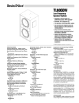
1
x•tant
x•tant (ikst`ænt, e`kstent) 1.
adj. still in existence, especially.
of enduring excellence .|| e.g.
of xtant quality that stands the
test of time and the passing of
fads. 2. adj. Standing out or
above, as in outstanding, the
quality or state of being original. [from. L. xstans (xstantis) n
present participle of xstare, to
stand forth. || Second origin;
Prescott AZ. U.S.A. Ntl. Frst.
Cmp. 1994 v. to xtantify = to
stand up and be heard] 3. noun
/XTANT applied creativity esp.
a company of people united to
apply original thinking to continually advance the spectrum
of extraordinarily vivid sound
reproduction, to apply innovative thought and action to
questions previously considered resolved .||
X t a n t Te c h n o l o g i e s
7676 South 46th Street Phoenix, Arizona 85040
(602) 431-8686 FAX (602) 431-8600
WELCOME
We would like to personally thank you for choosing Xtant
Technologies equipment. Our mission is to continually provide you with
the best mobile audio – anywhere. Our goal is to exceed your expectations. Our driving concepts are superiority through simplicity, flexibility,
compatibility, reliability, efficiency, and ease of system expansion. We
began with a clean slate. We challenged all the assumptions. We enlisted a dream team of audio specialists: manufacturers, installers, designers and audiophiles. We all became excited about the possibilities. We
listened. We are still listening.
We Listen to your recommendations, opinions, and needs.
We Listen to our fellow supporting manufacturers to ensure that our
products interface well with a wide variety of products.
We Listen to our equipment with sensitive and critical ears to provide the finest mobile audio components on the planet.
We have created Xtant because we respect the music, and the people
who want to really listen. The result has expanded the expectations of
extraordinarily vivid mobile audio. Vivid mobile audio, a continuing evolution of the art of listing and hearing, well. We believe that music
deserves the maximum accuracy in reproduction. We have united art of
the technology and the technology of the art to create the magic. Xtant
is only available through the finest specialized mobile audio retailers.
Your Xtant Select Dealer was chosen by us because of their passion for
excellence and their commitment to expanding their expertise. Please
remember, exceptional audio requires professional installation. Your
Xtant Dealer will optimize your system and your level of satisfaction.
Whether you are a professional competitor in autosound or a privately passionate connoisseur of fine music, we salute you, and appreciate your investment in quality mobile audio. If you have a problem or a
suggestion please give us a call or write us. Thanks for having the faith
in the music and the faith in us.
We look forward to a long and enduring relationship!
Welcome to Xtant!
TABLE OF CONTENTS
Safeguards
4
glossary of terms
5
Xtant 121m
6
Xtant 202m
7
Xtant 404m
8
Specifications
9
INSTALLATION
10
Optional Accessory Modules
15
ADDING ACCESSORY MODULES
16
121m low pass crossover
17
Service jumper
17
TROUBLESHOOTING
18
Customer SERVICE
19
Warranty
20
SAFEGUARDS
Please take the time to read this Owners Manual. The
following guidelines are designed to assure a safe and
properly installed Xtant Mobile Audio System.
All Xtant amplifiers and accessories are intended to be installed by a certified mobile audio installation specialist. It is the recommendation of Xtant
Technologies that your new Xtant amplifier(s) and accessory module(s) as
well as all of your mobile audio equipment be installed by your Authorized
Xtant Dealer.
Caution!
The use of a high-powered, mobile audio sound system may cause damage or hearing loss. Listening at loud volume levels may impair your
ability to hear traffic sounds, and therefore, may constitute a traffic
hazard. Xtant advises lower volume levels while driving.
Keep Your Sales Receipt
Your Xtant amplifier has an industry leading four year warranty when
installed by an Authorized Xtant Dealer. Non Authorized Xtant Dealer
installed products carry a limited one-year warranty. To establish the
starting date of warranty coverage, a copy of your sales receipt must
accompany your amplifier for all warranty service. Please file your sales
receipt away for future reference. For your convenience, a complete limited warranty statement is located at the back of this manual.
Follow Instructions
Follow all use and installation instructions to assure proper operation of
your new Xtant M Series amplifier.
Wiring Requirements
All Xtant amplifiers have minimum wire gauge requirements for Power,
Ground, Remote Turn-On, and Speaker Cables. Please refer to this manual for the recommended wire gauges for each application.
Fusing Requirements
M Series amplifiers are not fuse protected! For safety, a fuse must be installed
in-line with the power wire within 12 inches of the battery. In the case of a multiamp system, use a fuse value equal to the combined total demand of all amplifiers in the system. A second outboard fuse may be added close to the amplifier
if desired. Refer to the fuse values listed on page 9 for the correct in-line fuse
value for your amplifier.
Water and Moisture
Install all Xtant amplifiers and accessories in a location free
of moisture or exposure to water.
4
glossary
The following terms are used in this manual. Since they
may be unfamiliar, the following definitions are provided.
Bridging:
Combining two amplifier channels into one channel.
Typically used to create a high-powered mono output.
Gain:
The ratio of output voltage to input voltage. The gain on
the M Series amplifiers has two different areas of adjustment. The input gain jumper offers 40 dB of input gain
adjustment while the front panel potentiometer offers 15
dB of amplifier output level adjustment.
LED:
Light Emitting Diode. The M Series uses 3 colored LED’s
to indicate the operational status of the amplifier. A RED
LED for power on/off, YELLOW for low impedance protection and ORANGE for thermal protection.
Load Impedance:
Measurement of speaker(s) resistance/reactance that the
amplifier must drive. The M Series protection circuitry
engages when a load impedance of less than 2 Ω’s is present.
Mixed Mono:
The amplifier’s ability to play the Left and Right Stereo
channels while playing a third (bridged) mono channel.
Module Port:
18 pin connector located inside the M Series amplifiers designed
to connect Xtant’s accessory modules. Each M Series amplifier
has two Module Ports for every two channels of input.
PWM:
Pulse-Width Modulated power supply. Our regulated PWM
maintains a high conversion efficiency over an input supply
range of 10.5–15 VDC. The result is less demand on the
battery, lower (amplifier) operating temperature, and
extremely accurate low frequency reproduction.
Remote Turn-On:
Low current, automatic switching circuit that turns the
amplifier on and off. Typically connected to the remote
antenna or amp turn-on lead of most car radios, cassette,
and CD players.
5
+ – + –
RCA INPUTS
GRND
SPEAKER CONNECTOR
OUTPUT GAIN
RM
+12V
POWER CONNECTOR
INPUT GAIN ADJUST
CROSSOVER BYPASS JUMPER
OUTPUT GAIN ADJUST
HORIZONTAL ACCESSORY PORT
VERTICAL ACCESSORY PORT
GROUND
REMOTE
SERVICE JUMPER
+12V
Standard Features
Regulated, PWM MOSFET Switching Power Supply
Discrete MOSFET Output Circuitry
Mono Design
Selectable 90 Hz Low-Pass Crossover
Balanced Line Input Circuitry
40 dB of Input Sensitivity – Adjustable in 10 dB Steps
Two Accessory Module Ports
Low Impedance Protection with Diagnostic LED
Thermal Protection with Diagnostic LED
Limited Four-Year Warranty
Designed, Engineered, and Handcrafted by Xtant in the U.S.A
6
GRND
+ – + –
RCA INPUTS
OUTPUT GAIN
SPEAKER CONNECTOR
RM
+12V
POWER CONNECTOR
INPUT GAIN ADJUST
OUTPUT GAIN ADJUST
HORIZONTAL ACCESSORY PORT
VERTICAL ACCESSORY PORT
REMOTE
GROUND
SERVICE JUMPER
+12V
+ – + –
Standard Features
Regulated, PWM MOSFET Switching Power Supply
Discrete MOSFET Output Circuitry
Balanced Line Input Circuitry
40 dB of Input Sensitivity – Adjustable in 10 dB Steps
Internally Bridgeable
Two Accessory Module Ports
Low Impedance Protection with Diagnostic LED
Thermal Protection with Diagnostic LED
Limited Four-Year Warranty
Designed, Engineered, and Handcrafted by Xtant in the U.S.A
7
FRONT INPUTS
REAR INPUTS
OUTPUT GAIN
OUTPUT GAIN
+ – + –
+ – + –
FRONT SPEAKERS
REAR SPEAKERS
GRND
RM
+12V
POWER CONNECTOR
HORIZONTAL ACCESSORY PORTS
INPUT GAIN ADJUST
OUTPUT GAIN ADJUST
VERTICAL ACCESSORY PORTS
GROUND
SERVICE JUMPER
FRONT CH.
+ – + –
FRONT CH.
+ – + –
REAR CH.
Standard Features
Regulated, PWM MOSFET Switching Power Supply
Discrete MOSFET Output Circuitry
Front and Rear Input – Balanced Line Circuitry
40 dB of Input Sensitivity – Adjustable in 10 dB Steps
Internally Bridgeable
Four Accessory Module Ports
Low Impedance Protection with Diagnostic LED
Thermal Protection with Diagnostic LED
Limited Four-Year Warranty
Designed, Engineered, and Handcrafted by Xtant in the U.S.A
8
REMOTE
+12V
REAR CH.
M Series AMPLIFIER SPECIFICATIONS
Model
121m
202m
404m
Watts per Channel @ 4 Ohms:
1 x 125 Watts
2 x 50 Watts
4 x 50 Watts
Watts per Channel @ 2 Ohms:
1 x 250 Watts
2 x 100 Watts
4 x 100 Watts
N/A
1 x 200 Watts
2 x 200 Watts
5 Hz to 50 kHz
5 Hz to 50 kHz
5 Hz to 50kHz
< 0.08%
< 0.08%
< 0.08%
> 100 dB
> 100 dB
> 100 dB
> 200
> 200
> 200
Unbalanced Source
100mV to 8.5V
100mV to 8.5V
100mV to 8.5V
Balanced Source
100mV to 17V
100mV to 17V
100mV to 17V
Output Impedance:
2 - 8 Ohms
2 - 8 Ohms
2 - 8 Ohms
Output Impedance (Bridged):
4 - 8 Ohms
4 - 8 Ohms
4 - 8 Ohms
10.5 to 15 Volts
10.5 to 15 Volts
10.5 to 15 Volts
30 Amp
30 Amp
50 Amp
11 x 1.8 x 8”
11 x 1.8 x 8”
15.5 x 1.8 x 8”
4 Yrs Parts & Labor
4 Yrs Parts & Labor
4 Yrs Parts & Labor
Bridged Mono Output @ 4 Ohms:
Frequency Response:
Distortion (THD):
Signal-To-Noise Ratio:
Damping Factor (@ 100 Hz into 4Ω load):
Input Sensitivity
Supply Voltage:
Fuse:
Dimensions:
Limited Warranty:
9
Installation
All Xtant amplifiers and accessories are intended to be
installed by a certified mobile audio installation specialist. It
is the recommendation of Xtant Technologies that your new
Xtant amplifier(s) and accessory module(s) as well as all of your
mobile audio equipment be installed by your Authorized Xtant
Dealer. If, however, you choose to install your Xtant amplifier yourself,
please take the time to read this manual. The following guidelines are
designed to assure a safe and proper installation of your Xtant Mobile
Audio Sound System.
Tools / Parts Needed for Installation (not supplied):
Small flat blade screwdriver
Wire cutters
Soldering iron
Flux cleaner
Spade Connectors
Speaker wire – 16 gauge or larger
Power and Ground wire – 8 gauge or larger
Phillips screwdriver
Wire strippers
Solder
Heat shrink
Grommets
In-line fuse holder and fuse
Silicone or similar material
Mounting
To prevent damage to you and the amplifier, mount it in a secure place.
Choosing the appropriate location will depend upon your vehicle and the
complexity of your system design. It may be mounted in any compatible
space that is convenient to your needs and provides sufficient airflow.
Adequate ventilation allows the amplifier to dissipate the heat that develops during operation.
Typical mounting locations include: trunk and passenger compartment.
Mounting the amplifier under a seat or in an enclosed area should only be
considered as a last resort. Never mount the amplifier in a location which
would subject it to immersion or exposure to water.
The M Series’ uniquely shaped heatsink is designed for high-efficiency
cooling, however, improper mounting may compromise its ability to cool.
When mounting the amplifier in a confined space, care must be taken to
ensure that at least two inches of clearance is provided around the amplifier. If the amplifier is located in an area which has restricted air-flow or is
totally enclosed, a fan may be used to improve air circulation.
Power and Ground
Before beginning, disconnect the negative (-) terminal of the battery before
working on the positive terminal to prevent a short to ground. Reconnect the
negative terminal only after all connections have been made.
10
M Series amplifiers are designed to operate from a car’s +12 volt, negative
ground electrical system. The power and ground cables should be a minimum of
8 gauge. Depending upon the complexity of your system, larger gauge wire may
be needed.
The main power cable should run from the amplifier location, through the vehicle to the battery, avoiding sharp corners, creases, and sharp body parts. When
passing through any metal wall (i.e. fire wall etc.), a grommet must be used to
prevent the wire from chafing and shorting to ground.
The M Series amplifiers do not have an on-board fuse. An outboard fuse must
be installed in-line with the power wire within 12 inches of the battery. Use
the following fuse values at the battery: 121m and 202m: 30 Amp; 404m: 50
Amp. If multiple amps are being used, the fuse value should equal the combined total demand of all amplifiers in the system. A second outboard fuse may
be added close to the amplifier if desired. Consult your Authorized Xtant Dealer
for an appropriate in-line fuse holder that meets the needs of your installation.
We suggest crimping and soldering all wire connections. Insulate the connection
with heat shrink to prevent a short to ground.
The ground wire should be of the same gauge as the power
wire. As a 'rule of thumb', use as short a length of wire as
possible. Locate an area near the amplifier that is metal (the
floor or an existing unused threaded bolt hole is ideal) and
+12V
clean the area to bare metal. Drill a pilot hole (if necessary) GROUND
in the middle of this area. Be Careful! Inspect the area
underneath to be sure you aren’t drilling into wires, brake or
fuel lines, etc. Terminate the wire with a ring connector and
attach it to the bare metal. We suggest crimping and soldering this connection. Insulate the connection with heat shrink. It is important
that this connection be solid. After the connection is complete, coat the area with
silicone or some similar material to prevent rust from developing.
Once the power and ground wires have been run, it’s time to connect the cable
to the amplifier. Be sure that you have not reconnected the ground cable to the
negative post of the battery. Cut off excess wire and terminate the wire with a
spade connector. We suggest crimping and soldering this connection. Insulate
the connection with heat shrink. Locate the power and ground connector. With
a small flat bladed or Philips head screw driver, loosen the terminal screws
marked: Ground and +12 Volts. Insert each spade connector and secure it by
tightening the associated screw. Be sure each connection is tight.
Remote Turn-On
In order for the amplifier to turn on, a remote turn-on wire must be connected
to a switched 12 volt source. Typically, the source unit provides a power
11
antenna (remote) turn-on lead which will turn on the
amplifier when the source unit is activated. If this is
unavailable, a switched 12 volt source must be used. Run
REMOTE TURN-ON
a wire from the amplifier location through the vehicle to
the switched 12 Volt source. Observe the same precautions for routing this cable that you followed for running
the power cable. Cut off excess wire and terminate the
wire with a spade connector. We suggest crimping and soldering this connection. Insulate the connection with heat shrink. It is important that this connection be solid. With a small flat bladed or Philips head screw driver, loosen the
terminal screw marked: Remote. Insert the spade connector into the appropriate location and secure it by tightening the associated screw. Be sure the connection is tight.
Speaker Connection
Run the speaker wires from the amplifier location
through the vehicle to the speakers. Observe the same
precautions for routing these wires that you followed for
running the power and remote turn-on cables. It is impor+ LEFT – + RIGHT –
tant to use 16 gauge or larger wire for proper signal
transfer. Cut off excess wire and terminate the wire with
spade connectors. With a small flat bladed or Philips
head screw driver, loosen the terminal screw marked:
Speakers. Insert each spade connector, one at a time, into the appropriate terminal. Check to make sure you’ve maintained proper polarity before securing
each wire. Be sure the connection is tight.
Bridging
All M Series amplifiers are capable of being bridged into a mono output due to
the internal design of the amplifier. This feature permits
the creation of a mono channel for a subwoofer or center
channel. Also, bridging adds flexibility of operation. The
202m, two-channel amplifier can be used in a one channel
RIGHT –
+ LEFT
(mono), two channel stereo, or 3 channel – 2 channels
stereo and one channel mono configuration. The 404m,
four-channel amplifier, can be used as 2 mono channels, 3
channels – 2 channels stereo and one channel mono, 4
channels – 2 channels front and rear, 5 channels – 4 channels stereo and one
channel mono, or 6 channels – 4 channels stereo and 2 channels mono.
12
Deriving the mono channel is accomplished by using the left channel positive wire as the positive speaker wire and the right channel negative wire
as the negative speaker wire. It is important that a minimum 4 Ohm impedance be observed.
Inputs
M Series Amplifiers feature RCA inputs only. Run RCA cables from your
sound source to the inputs of the amplifier. We suggest the use of high quality shielded RCA patch cords to help reduce or eliminate unwanted noise in
your installation. Be sure to run the RCA cables on the opposite side of the
vehicle that you used to carry the power leads to the amplifier.
The input stage of the M Series amplifiers incorporates Xtant’s Balanced
Line circuitry. This circuitry may be “enabled” or “disabled” via the
Balanced Input Mode Jumper located above the RCA input jacks. With the
Balanced Line circuitry “enabled”, the input sensitivity ranges from 100mV
to 17 Volts. When in the “disabled” mode, input sensitivity ranges from
100mV to 8 Volts. Input sensitivity is adjustable in 10 dB steps via the Input
Gain Select Jumper located above the Balanced Input Mode Jumper. Each of
the five jumper positions correlate to a specific range of input signal levels.
The chart below details the relationship between the jumper position and
input signal level.
ADJUSTING INPUT SENSITIVITY
INPUT JUMPER
-20 dB
-10 dB
0 dB
+10 dB
+20 dB
SIGNAL LEVEL
=
=
=
=
=
10 to 17 Volts
3 to 8 Volts
1 to 3 Volts
300 mV to 1 Volt
100 to 300 mV
The amplifier is shipped with the input gain set at the +10 dB position. If you
do not know the output signal level of your head unit and you want to
change the factory setting, simply move the jumper to the +20 dB position
to increase the gain. Move the jumper to the 0, –10 or –20 dB position to
decrease the gain.
The input circuitry operates similar to a line driver by increasing the signal
level when placed in the +10 and +20 dB positions. The following chart illustrates this function:
13
I N P U T V O L TA G E M U L T I P LY I N G F A C T O R
INPUT JUMPER
+20 dB
+10 dB
0 dB
–10 dB
–20 dB
MULTIPLYING FACTOR
=
=
=
=
=
10
3
1
.3
.1
(ie: A head unit with 300mV output with input jumper @ +20dB = 3 Volts input)
The input stage may be over-loaded by a high-level signal if the input
gain is set too high. If this should occur, simply reduce the input sensitivity setting.
USING THE BALANCED LINE CIRCUITRY
The Balanced Line circuitry provides two unique features which add
versatility to your head unit selection. First, the Balanced Line circuitry
increases the input sensitivity to 17 Volts when receiving a signal from
a balanced source and, secondly, isolates signal ground. These two features allow connection with OEM factory head units and high-powered
(BTL) head units. The Balanced Line circuitry will also accept a speaker
level input signal. If the head unit has a Floating Ground output, you
must “enable” the Balanced Line circuitry prior to connecting the head
unit. Failure to “enable” the Balanced Line may result in damage to the
head unit.
The Balanced Line circuitry also helps eliminate noise (ie alternator
whine) induced into the signal cables. If you are experiencing a noise
problem, simply “engage” the Balanced Line circuitry. If the problem
continues, call Xtant Technologies’ Customer Service at 602•431•8686
for assistance.
output Gain Control
The output gain (for each 2 channels) is controlled by a board-mounted
potentiometer located next to the inputs. Xtant suggests setting this
level in conjunction with any equalization or signal processing equipment in the system. Upon installation of the amplifier, the output gain
control should be adjusted. Using a small flat blade screwdriver, first
turn the output gain all the way down (counter clockwise). Turn the volume on the source unit up two thirds. Then adjust the output gain control until the desired volume is obtained without audible distortion. If
more gain is desired, adjust the input gain setting to the +20 dB position
and reset the output gain. It is important to note that the output gain is
adjusted independently from the Input Gain Select.
14
OPTIONAL ACCESSORY MODULES
Xtant optional accessory modules are easily and quickly
installed by your Authorized Xtant Dealer. The upgrade
modules snap into place on the amplifier’s PC board when the top of the
unit is removed. These accessories enhance your entire system, expanding and customizing performance for your unique application.
PARAMETRIC EQUALIZATION MODULE – PQM 1
The PQM-1 is a precision tuning instrument, designed
to be adjusted with the use of a Real-Time-Analyzer.
This true, fully adjustable, one band parametric equalizer provides individual frequency, Q (bandwidth), and
gain adjustments. Any frequency from 20 Hz to 20 kHz can be
chosen. The “Q” ranges from 1 to 10 in value, providing a wide range of
adjustment to address the subtle tuning requirements common with
most mobile audio systems.
BASS BOOST MODULE – LFQ 45
The LFQ 45 is a bass boost module with selectable gain. Centered at 45
Hz, each of the three gain settings (+4, +8 or +12 dB) will add varying levels of low frequency impact to any Xtant system.
24 dB / OCTAVE CROSSOVER MODULE – CM 24X
The CM 24x is a 24 dB per octave “Linkwitz - Riley”
crossover filter. The CM 24x module improves loudspeaker polar response while its steeper slope provides
enhanced system design flexibility.
12 DB / OCTAVE FILTER MODULES – CM 12H & CM 12L
The CM 12H and CM 12L are 12 dB per Octave “Butterworth” filter networks dedicated to either a High-Pass function (CM 12H) or Low-Pass
function (CM 12L). Each module is designed to be plugged into any
accessory port on Xtant’s M Series amplifiers. Frequency adjustment is
via a 12 pin plug-in resistor SIP and 13 different frequency SIPS are available from your Xtant Select Dealer.
15
Adding Accessories Modules
Xtant offers two types of accessory modules which
are designed for either “Horizontal” or “Vertical”
mounting. The docking port(s), located on the amplifier’s circuit board, labeled Horiz Acc Port will accept any module,
while the port(s) labeled “Vert” will only accept modules designed
for vertical mounting. Please refer to the following list for module/amplifier compatibility as well as their mounting orientation.
Expansion Module Compatibility
NGM 1
CM 24x
PQM 1
LFQ 45
CM 12 H
CM 12 L
RM 4
RM 8
RM 12
RM 16
RGM 1
M Series
yes
yes
yes
yes
yes
yes
no
no
no
no
yes
A Series
yes
yes
yes
yes
yes
yes
yes
yes
yes
yes
yes
X Series
Incl.
Incl.
yes
yes
N/A
N/A
Yes
Incl.
Yes
Yes
yes
Mounting
Horizontal
Horizontal
Horizontal
Vertical
Vertical
Vertical
Horizontal
Horizontal
Horizontal
Horizontal
Horizontal
The accessory ports allow you to add the level(s) of signal processing that you desire. For example, if a band pass crossover is
desired, a CM 12 H (high pass at the lowest frequency of the band
pass) and a CM 12 L (low pass at the highest frequency of the band
pass) could be used to create a 12 dB per octave band pass filter.
A more basic set-up would be a PQM-1 EQ module and a CM 12 ( L
or H ) crossover module.
16
Setting the 121m’s Low Pass crossover
The 121m comes with an on-board, low pass
crossover. This type of electronic crossover is needed
when playing most subwoofer systems. The crossover
is a 12 dB per octave “Butterworth” configuration with a
fixed crossover frequency of 90 Hz.
The amplifier is shipped with the low pass crossover active.
To turn-off the crossover, simply move the crossover bypass
jumper (see page 6 and below) from the “XOVR” position to
the “BYPASS” position.
Crossover Jumper settings
“XOVR”
“BYPASS”
With the jumper in
this position, the
crossover is active
With the jumper in
this position, the
crossover is not active
Using the Service JUmper
All M Series amplifiers are equipped with a “service
jumper” (see page 6, 7 & 8 and below). This jumper provides a simple means of turning the amplifier on or off at
the amplifier.
The “service jumper’s” position will either pass or interrupt
the remote turn-on voltage being sent from your source unit to
trigger the amplifier’s turn-on circuitry. With the amplifier playing,
simply move this jumper to the “Disable” position to temporarily
turn-off the amplifier. Move the jumper to the “Enable” position
to turn the amplifier back-on. Here are a few examples of when
to use the “service jumper”:
• adjusting input sensitivity
• adding an accessory module
• adjusting an accessory module
service Jumper settings
“DISABLE”
“ENABLE”
With the jumper in
this position, the
remote turn-on lead
is not connected
With the jumper in
this position, the
remote turn-on lead
is connected
17
TroubleShooting
DIAGNOSTIC LED’S
The Red LED indicates that the amplifier is on.
The Yellow LED indicates that an over-current condition (low impedance) exist and will turn the amp’s output power down to maintain uninterrupted operation. The Yellow LED will light if a speaker load falls
below the M Series’ 2Ω rating and/or a speaker lead / speaker voice coil
is shorted.
The Orange LED indicates that an over-heating condition exists and will
turn the amp’s output power down to maintain uninterrupted operation.
The Orange LED will light if the heatsink temperature exceeds rated
spec due to poor ventilation.
Symptom/Condition
Cause
Solution
Red LED not on. No Sound.
Loss of 12V Power at Amplifier
Check out-board fusing
Check +/– 12 Volt connections
Measure for + 12 Volts or higher
@ amp. Check Turn-On lead
Red LED on. No Sound.
No Input Signal
Check integrity of RCA cables
Check connection at amp and
head unit.
Red LED on. No Sound.
Loose Speaker Wires
Check integrity of speaker
connection at amp and speakers.
Red LED on. No Sound.
Lack of Turn-On Voltage
Voltage @ Turn-On lead needs
to be 8 Volt minimum
Red LED on. No Sound.
Missing Accessory Port Jumper
Check Port Jumpers, two jumpers
per port are required. Check
jumper alignment, jumper must
be seated properly.
Red LED on. No Sound.
Accessory module is not
installed properly
Be sure “key” on module connector
and port are aligned when
installing module. Reseat module
to insure proper connection.
Induced noise / ground loop
“Enable” Balanced Input
Alternator/System Noise
18
CUSTOMER RELATIONS
TECHNICAL SERVICES
STATEMENT OF PURPOSE
Our customer’s satisfaction is our purpose. You represent our present and future. Our goal is to create
and nurture relationships based upon trust and
respect. This commitment is not taken lightly or just
for today; it is our way of doing business. We believe
there is no other way.
Xtant’s policies and procedures are designed, in the
event of a problem, to minimize the amount of your
“down-time” and inconvenience. It is our commitment that the product will be at our facility for no
more than four (4) days. Please consider weekends
or holidays (which may fall within the time period)
when estimating the return date of serviced product.
For technical assistance and information regarding
products and/or installation, please contact Xtant’s
Customer Service Department from 8:00 am to 5:00
pm MST– Monday thru Friday at:
Phone:
Fax:
U.S.A. Toll free:
(602) 431 8686
(602) 431 8600
(888) 449 8268
19
LIMITED U.S.A. WARRANTY
This warranty gives you specific legal rights, and you may also have other
rights which vary from state to state. Xtant Technologies (Xtant) warrants its
products to be free from defects in materials and workmanship under normal
use and service when the unit is installed by an Authorized Xtant Dealer as
folows: electronics (4) four years from original purchase date; speakers/subwoofers (3) three years from original purchase date. Non-Authorized Dealer
installed products carry a one (1) year parts and labor limited warranty. The extent
and conditions of Xtant’s Limited Warranty are as follows:
1. Authorized Xtant Dealer Installed Products: Xtant will repair at no charge, to the original purchaser, any unit which Xtant’s examination discloses to be defective and under warranty, provided
the defect occurs within the warranty period and the product is returned immediately to Xtant. This
warranty is not transferable.
2. Non-Authorized Xtant Dealer Installed Products: Xtant will repair at no charge, to the original purchaser, any unit which Xtant’s examination discloses to be defective and under warranty, provided
the defect occurs within one (1) year from the date of purchase and the product is returned immediately to Xtant. This warranty is not transferable.
3. The date of purchase and proof of Authorized Dealer Installation of an Xtant product must be
established by an original (or copy of the original) sales receipt which must accompany the article being returned for warranty work.
4. This warranty shall NOT apply to any Xtant unit found to have the original factory serial number
removed or defaced. All products received (by Xtant) for in warranty or out of warranty repair, with
their original serial numbers removed or defaced, will NOT be repaired and will be returned to
sender, freight collect.
5. The provisions of this warranty shall not apply to any Xtant unit used for a purpose for which it is
not designed, which has been repaired or altered in any way, or which has been connected, installed,
or adjusted other than in accordance with the instructions furnished in Xtant’s owner’s manual. Nor
shall this warranty apply to any part which has been subject to misuse, neglect, or accident.
6. Xtant does not authorize any other persons to assume any other liability in connection with its
products. THIS WARRANTY IS THE ONLY EXPRESS WARRANTY MADE BY XTANT APPLICABLE TO
ITS PRODUCTS. ANY IMPLIED WARRANTY OR MERCHANTABILITY OR FITNESS FOR A PARTICULAR PURPOSE APPLICABLE TO XTANT’S AMPLIFIERS AND OR ACCESSORIES IS LIMITED IN
DURATION TO THE DURATION OF THIS LIMITED WARRANTY. XTANT SHALL NOT BE LIABLE
FOR THE INCIDENTAL, CONSEQUENTIAL, OR COMMERCIAL DAMAGES RESULTING FROM THE
BREACH OF THIS WRITTEN WARRANTY. Some states or provinces do not allow the exclusion or limitation of incidental or consequential damages or limitations on how long an implied warranty lasts;
so the above limitations or exclusions may not apply to you.
7. Your unit will be serviced on an in-warranty basis within the warranty period for the correction of
warranted defects. If improper operation of your Xtant product should occur, contact your Authorized
Xtant Dealer for assistance with the return and factory repair of your Xtant product. If an Authorized
Xtant Dealer is not available, please contact Xtant’s Customer Service Department for assistance.
ELECTRONICS
X t a n t Te c h n o l o g i e s
7676 South 46th Street
Phoenix, Arizona 85040
888-449-8268
SPEAKERS
X t a n t Te c h n o l o g i e s
805 Woodman Ave.
Winslow, Il 61089
800-556-2888
TO RETURN XTANT PRODUCTS OUT OF WARRANTY: Contact Xtant’s Warranty Department at
(602) 431 8686 from 8:00 am to 5:00 pm (MST) for a Return Authorization Number. Return the unit,
postage prepaid, in the original protective carton. Please include a description of the problem and, if
desired, a request for an estimate of repair costs. Unless a request for an estimate is included, the
unit will be repaired as necessary. Repaired unit will be returned with an itemized statement, C.O.D.
certified or Visa/MC. Xtant provides a 90 day warranty on all repairs serviced as non-warranty units.
20