1
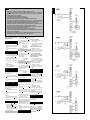
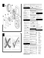
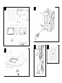
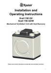
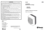
‘‘``````
Xpelair
Guarantee
UK: The fan is guaranteed against defects for 3 years from the date of purchase.
• Xpelair reserve the right to repair or replace the fan.
• Keep your purchase receipt.
• Any problems, contact the address below.
Safety Extra Low Voltage
Centrifugal Ducted Fans
Technical Advice & Service
UK: Xpelair have a comprehensive range of services including:
• Free technical advice Help-Desk from Engineers on all aspects of ventilation
• Free design service, quotations and site surveys
Outside UK: See International section below.
Please ask for details on:
Tel
+44 (0) 8709 000430
Fax
+44 (0) 8709 000530
Also at the address below
• LVDX200 Standard
• LVDX200T Timer
Head Office – UK Sales Office and Spares
• LVCF20 Pull Cord
• LVCF20T Pull Cord/Timer
Condensation Control Fans
Applied Energy Products Ltd, Morley Way, Peterborough, PE2 9JJ, England
Tel:
+44 (0) 1733 456789
Fax:
+44 (0) 1733 310606
Sales/Spares Hotline:
+44 (0) 8709 000420
Sales/Spares Faxline:
+44 (0) 8709 000520
Web:
http:/www.xpelair.co.uk
Installation and Maintenance Instructions
Retain for future reference
International
Guarantee – Contact your local distributor or Xpelair direct
Technical advice and Service – Contact your local Xpelair distributor.
567-2069-01
Revision D
8
IMPORTANT
1.
2.
READ ALL THESE INSTRUCTIONS & WARNINGS FULLY BEFORE COMMENCING INSTALLATION.
INSTALLATIONS AND WIRING MUST CONFORM TO CURRENT IEE REGULATIONS (UK), LOCAL OR APPROPRIATE
REGULATIONS (OTHER COUNTRIES). IT IS THE INSTALLER’S RESPONSIBILITY TO ENSURE THAT THE APPROPRIATE
BUILDING CODES OF PRACTICE ARE ADHERED TO.
3. A QUALIFIED ELECTRICIAN MUST SUPERVISE ALL INSTALLATIONS.
4. THESE APPLIANCES ARE INTENDED FOR CONNECTION TO FIXED WIRING.
5. CHECK THAT THE ELECTRICAL RATING SHOWN ON THE TRANSFORMER MATCHES THE MAINS SUPPLY.
6. SITE BOTH FAN AND TRANSFORMER AWAY FROM DIRECT SOURCES OF HEAT (I.E. GAS COOKERS OR EYE LEVEL
GRILLES. THE FAN MUST NOT BE MOUNTED WHERE AMBIENT TEMPERATURES ARE LIKELY TO EXCEED 40ºC. THE
TRANSFORMER MUST NOT BE MOUNTED WHERE AMBIENT TEMPERATURES ARE LIKELY TO EXCEED 40ºC.
7. WHEN THE FAN IS INSTALLED IN A ROOM CONTAINING A FUEL BURNING APPLIANCE, THE INSTALLER MUST ENSURE
THAT AIR REPLACEMENT IS ADEQUATE FOR BOTH THE FAN AND THE FUEL BURNING APPLIANCE.
8. ENSURE THAT ALL RELEVANT SAFETY PRECAUTIONS (CORRECT EYE PROTECTION AND PROTECTIVE CLOTHING ETC)
ARE TAKEN WHEN INSTALLING, OPERATING AND MAINTAINING THIS FAN.
9. GENERAL GUIDANCE FOR SITING THE FAN SEE “FIG.G”. ALWAYS SITE FAN AS HIGH AS POSSIBLE.
10. IF ANY SECTION OF THE DUCTWORK IS POSITIONED HIGHER THAN THE FAN A CONDENSATION TRAP (XCT100) MUST BE
FITTED AS CLOSE AS POSSIBLE TO THE FAN.
11. THIS APPLIANCE IS NOT INTENDED FOR USE BY YOUNG CHILDREN OR INFIRM PERSONS WITHOUT SUPERVISION. YOUNG
CHILDREN SHOULD BE SUPERVISED TO ENSURE THEY DO NOT PLAY WITH THE APPLIANCE.
For speed and ease of installation, your LVCF20 / LVCF20T Only (Fig. D)
installation may require some of the Ancillaries 4. The correct condensation control speed should
indicated in “Ancillary Options”.
be selected to suit the room size in which the
fan is to be installed. Slide the switch X to the
If installing the fan on a wall (surface
required position. Please note that the fan is
. mounting)
factory set to “Position 2”.
1. Mark on the wall the centre of the duct hole A. 5. Switch Position Size / Room Volume (m³)
2. Use this centre to cut an opening through the
1
Large (34 and above)
wall 117mm dia. with a slight fall to the
2
Medium (28 – 34)
exterior.
3
Small (less than 28)
3. Fit the wall tube (not supplied), and motar into
Setting the trickle speed
place.
LVCF20 / LVCF20T Only (Fig. D)
If installing the fan in a wall (flush mounting)
6. The fan can be set so that it provides constant
trickle extraction. Slide the switch Y to the
1. Mark on the wall the centre of the duct hole A,
required position. Please note that the fan is
and drill a pilot hole through both walls.
factory set to “Position 0”.
2. Use the centre to mark a rectangular hole for
7. Switch Position Setting
the inner wall using the dimensions A.
0
Trickle extraction OFF
3. Cut the rectangular hole through the inner
1
Trickle extraction ON
wall.
4. Go outside and cut a 117mm diameter hole in
Setting the time delay start
the outer wall using the small hole as the
LVDX200T / LVCF20T Only (Fig. D)
centre.
8. The fan can be set so that there is a 2-minute
5. Measure the wall thickness.
delayed start to its operation when used with
6. Cut the wall tube (not supplied), so that it is
an external on/off switch. Slide the switch Z to
64mm less than the wall thickness.
the required position. Please note that the fan
If installing the fan on a ceiling (surface
is factory set to “Position 0”
mounting)
9. Switch Position Setting
This method requires a space above the ceiling, such
0
Time delay start OFF
as a loft or attic, to provide access for 100mm
1
Time delay start ON
internal diameter ducting.
Mounting the Fan
1. Mark on the ceiling the centre of the duct hole The fan must not be mounted where ambient
A, avoiding ceiling joists and buried cables temperatures are likely to exceed 40°C.
etc.
Mounting the fan on a wall or ceiling (surface
2. Cut a 117mm diameter hole using the marked
mounting)
centre.
1. Place the ducting into the hole and align to the
If installing the fan in a ceiling (flush
required position. If wall mounting, ensure that
mounting)
the ducting slopes down and away from the
For 100mm diameter ducting:
fan.
This method requires a space above the ceiling, such
2. Mark the positions of the three fixing holes A
as a loft or attic, to provide access for 100mm
in fan box ? (Fig. E).
internal diameter ducting.
3. If wall mounting, drill three holes 5.5mm
1. Mark a rectangular hole using the dimensions
diameter for wall plugs (supplied). If ceiling
B.
mounting B, use appropriate fasteners (not
2. Cut the hole, avoiding ceiling joists and buried
supplied).
cables etc.
4. Cut out the cable inlet hole, if required, in the
For flat ducting:
surround ? and slit the cable grommet. Slide
the surround ? over the fan box ?.
•
This fan can be installed within a 50mm void
without the circular spigot ? (Fig. E). Flat ducting 5. Pass the electrical cables into the fan box ?
through the rear cable inlet hole and surround,
adapter kit (FDA) available.
and re-fit the cable grommet. Ensure that the
Preparing the fan for installation
cable grommet is in place and a tight fit.
1. Remove the front cover • (Fig. C)
6. Offer the fan box ? up to the wall or ceiling.
Ensure the circular spigot ? enters the
2. Fit the foam tape
supplied around the
ducting.
circular spigot ? (Fig. E).
3. Remove the electrical cover • (Fig. E). The 7. Fix the fan box ? to the wall using screws ?
or to the ceiling using appropriate fasteners
impeller can be removed to ease access (if
(not supplied).
required). This is a push on/pull off assembly.
Setting the condensation speed
If mounting the fan in a wall (flush mounting)
2
F
The surround ? is not required. Fit the ducting to
the circular spigot ?.
If the hole size is as recommended:
1. Assemble the three fan body clamps ? to the
fan box ? using screws ?.
2. Slit the cable grommet. Pass the electrical
cables into the fan box ? through the cable
inlet hole and cable grommet.
Ensure cable grommet is in place and a tight fit.
3. Offer the fan box ? up to the wall.
4. Tighten up the three screws ? until the fan is
clamped to the inner wall. The fan body
clamps ? will rotate to an automatic stop
position. DO NOT OVERTIGHTEN.
If the hole size is larger than recommended i.e.
larger than the flange on the fan box ? (Mostly
related to “retro-fit” installations):
1. The fan body clamps ARE NOT suitable.
Construct a wooden frame of INTERNAL
dimensions 203 x 233mm. Depth should be at
least 50mm. Fit the wooden frame into the
internal wall and make good the hole.
2. Offer the fan box ? up to the wall.
3. Screw the fan box ? to the wooden frame
using the slots in the flange (screws not
supplied).
If mounting the fan in a ceiling (flush
mounting)
1. The surround ? is not required.
2. Insert the fan box ? into the hole and mark
four positions using the slots in the flange B.
3. Remove the fan box ? from ceiling and fit the
four ceiling clips (supplied) over the edge of
the hole, so that the clips align with the marks
on the ceiling B.
4. Drill 4 pilot holes into the ceiling through the
hole of each clip, ensuring not to damage the
clip, and fit the clips ensuring correct
alignment.
5. Fit the ducting to the circular spigot ?.
6. Offer the fan box ? up to the ceiling.
7. Slit the cable grommet. Pass the electrical
cable into the fan box ? through the front
cable inlet hole.
Ensure cable grommet is in place and a tight fit.
8. Using the screws 11 (Fig B), fix the fan box
flange to the ceiling clips.
Terminating the ducting
Fit an outer grille (CF20 variants only) to the outer
wall. For ceiling mounting, use appropriate
ancillaries (not supplied).
Mounting the transformer
The transformer A can be fixed directly to the wall.
The transformer can be sited in a loft or in a
convenient position on a wall (not ceiling). The
transformer must not be covered by loft
insulation. For wall mounting the Fan must be
orientated as shown in H to fulfil ingress
protection requirements.
7
The transformer must also not be mounted
within 0.6m of a bath or shower cubicle, up to a
height of 2.25m.
The transformer must not be mounted where
ambient temperatures are likely to exceed 40°C.
Fixing the transformer directly
1. Remove the two screws securing the cover,
remove cover.
2. Position the transformer on the wall, and mark
the two fixing holes.
3. Drill and plug the two holes and fix the
transformer with the screws supplied.
For loft mounting:
The transformer can be fixed to a wooden surface
with the two screws supplied.
For fixed surface wiring:
Use the rectangular knockouts on each side (X).
These accept 25 x 16mm trunking (not supplied)
For concealed wiring:
Use the round knockouts (Y).
For connection to a window mounted fan:
Use knockout (Z). Use flexible cable.
When using the side entries with flexible cable, a
hole suitable for the cable size must be made
centrally in the rectangular section.
E
Wire the Fan
1.
Isolate the electricity supply and remove all
fuses.
The terminal block will accept cable up to
1.5mm².
2. A means for disconnection in all poles must be
incorporated in the fixed wiring in accordance
with the wiring rules.
3. Use suitably rated 3-core or 4-core cable
dependent on application.
4. Remove the retaining screws of the terminal
cover •, if still in position.
5. Wire the fan as shown in F using the cable
clamp provided. Check fan model to diagram.
LVDX200T: “LH” = Live (High Speed) /
“LL” = Live (Low Speed)
6. Replace the terminal cover • and fasten the
retaining screws.
7. See section on “User adjustments” if you wish
to use settings other than those that have been
factory set.
8. Refit the front cover • (Fig. C).
9. Connect the cable from the isolating switch to
electrical supply wiring, and re-check
installation.
10. Refit fuses before turning on electricity supply.
11. For fixed wiring circuits, the protective fuse
for the appliance must not exceed 5A.
G
For Australia Only
LVCF20 – Connection to the supply – flexible 3core cable with 3 pin plug top for insertion into an
approved 10A wall mounted surface switch with at
least 3mm clearance between contacts.
ALL OTHERS – Permanently connected to the
supply and a remote switch controls operation. They
should be directly wired to the supply through an
approved 10A wall mounted surface switch with at
least 3mm clearance between contacts.
Wire the Transformer
Always wire via the cable clamp.
1. Remove the cable clamps.
2. Wire the transformer as shown in F. Check the
fan model to diagram.
3. Ensure all connections are tight.
4. Replace the clamps and two screws. Ensure the
cable is firmly retained by the clamp.
5. Replace the transformer cover with the two
screws.
6. Switch off the mains electrical supply and
remove fuses.
7. Connect the cable from the isolating switch to
the electrical supply wiring.
8. For fixed wiring circuits the protective fuse for
the appliance must not exceed 5A.
User adjustments
6
Before making any adjustments, isolate the fan
completely from the mains supply, check
specification below to see which features apply to
your fan.
1. Remove the front cover and replace after
adjustment (Fig. C).
LVDX200
There are no user adjustments for the LVDX200 fan.
operating at high speed. Note: If the separate on/off
switch and integral pull cord are both on, the lights
“I” and “II” will both be lit and the fan will run at
high speed.
Trickle feature on or off
This is set by the installer to provide continuous
background extraction, when the humidity level is
below that set by adjusting screw “RH”.
LVCF20T only
LVDX200T
Time delay stat feature on or off
1. The timer over-run period can be adjusted This is set by the installer to provide a 2-minute time
between approximately 30 seconds and 20 delay start when the fan is switched on using a
minutes. Use an electrician’s screwdriver and separate on/off switch.
turn screw “T” (Fig. D), clockwise to increase
Cleaning
time, anti-clockwise to decrease. (Factory
preset to approximately 10 minutes).
1. Before cleaning, isolate the fan completely
from the mains supply.
LVCF20
2. Only clean the external surface of the fan,
1. The humidity setting is adjustable between
using a damp lint free cloth.
approximately 50% and 90% relative 3. Do not use strong detergents, solvents or
humidity. Use an electrician’s screwdriver, and
chemical cleaners.
turn screw “RH” (Fig. D), clockwise to 4. Allow the fan to dry thoroughly before use.
increase the relative humidity setting and anti- 5. Apart from cleaning, no other maintenance is
clockwise to decrease. (Note: the fan is more
required.
sensitive at 50% RH than at 90%).
Key
LVCF20T
See Diagram E
1. The timer over-run period can be adjusted 1. Baffle Plate
between approximately 30 seconds and 20 2. Front Cover
minutes. Use an electrician’s screwdriver and 3. Impeller
turn screw “T” (Fig. D), clockwise to increase 4. Fixing Screws
time, anti-clockwise to decrease. (Factory 5. Terminal Cover
preset to approximately 10 minutes).
6. Fan Box
2. The humidity setting is adjustable between 7. Circular Spigot
approximately 50% and 90% relative 8. Clamp screws and wall plugs – 3 off
humidity. Use an electrician’s screwdriver, and 9. Fan body clamps – 3 off
turn screw “RH” (Fig. D), clockwise to 10. Surround
increase the relative humidity setting and anti- 11. Ceiling screws 25mm long - 4 off (Diagram B)
clockwise to decrease. (Note: the fan is more 12. Foam Tape
sensitive at 50% RH than at 90%).
PLEASE LEAVE THIS LEAFLET WITH THE
Using the Fan
FAN FOR THE BENEFIT OF THE USER
Ancillary Options
LVDX200
Operate the fan using the external On/Off switch.
Repeat to switch off. The fan speed is pre-set by the
Installer to either high or low speed.
Both speeds can be selected when wired through a
change over switch Part No. 90108AW.
For speed and ease of installation, your installation
may require some of the Ancillaries listed below:
WD100
CFWG100
XCT100
DGW/B
SP100
XAA
VC10
WT10
XF/FM
Wall Duct
Wall Grille
Condensation Trap
Air Replacement Grille
Spigot Plate
Air Brick Adaptor
Vent Cowl
Termination Ducting Kit
Flat Ducting (Plastic/Metal)
(Plastic 234x29
Metal 230x25)
Wall Vent Kit
Flexible Ducting
Worm Drive Clips
Ceiling Mounting Kit
In-Line Back Draught Shutter
Easy Fit Termination Kit
Glass Mounting Adaptor
Grease Filter
Flat Duct Adaptor Kit
LVDX200T
Operate the fan using the external on/off switch.
Repeat to switch off.
When the switch is turned off, the fan continues to
operate for the selected over-run timer period. Top
light “I” is lit when the external on/off switch is
turned on.
The fan speed is pre-set by the installer to either
high or low speed. (If a change over switch has been VK10
installed then the user can switch between high FD100
WDC5
speed and low speed.)
XCMK
XBP
Time delay start feature on or off
This is set by the installer to provide a 2-minute time EFT
delay start when the fan is switched on using the GMK
PDXGF
external on/off switch.
FDA
LVCF20 / LVCF20T
Spares
Switched Operation
Listed below are some of the spares available. See
The fan can be wired with a separate on/off switch.
back page of this booklet for ordering details:
Fan operates at condensation speed when switched
on. Top light “I” is lit when the separate on/off 41756SK
Motor (LVDX200T)
switch is switched on. When switched off, the fan 41757SK
Motor (LVCF20/LVCF20T)
will continue to operate if the humidity level has not 41758SK
PCB Assy. (LVDX200T)
reached that set by adjusting screw “RH”. 41759SK
PCB Assy. (LVCF20)
LVCF20T only: When switched off, the fan 41760SK
PCB Assy. (LVCF20T)
continues to operate for the adjustable timer over- 41769SK
Front Cover c/w Baffle
run period.
(LVDX200T)
41770SK
Front Cover c/w Baffle
Condensation Operation
The fan operates at condensation control speed,
(LVCF20 / LVCF20T)
when the relative humidity exceeds the set level, and 41740SK
Surround Moulding
turns off when the humidity drops.
(Entire Range)
41741SK
Pull-Cord Assembly
Boost Operation
The integral pull cord switch switches the fan to run
(Entire Range)
at high speed. Bottom light “II” is lit when the fan is 41742SK
Impeller (Entire Range)
3
A
C
D
H
B
4
5