1
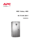
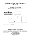
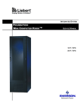
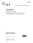
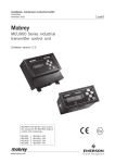
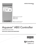
OPERATION and MAINTENANCE
MANUAL
for
MODEL PV-30208
30 kW Grid-Tied Photovoltaic Inverter
Document #151315
Revision E November 17, 2003
IMPORTANT SAFETY INSTRUCTIONS
SAVE THESE INSTRUCTIONS - THIS MANUAL CONTAINS IMPORTANT INSTRUCTIONS
FOR XANTREX TECHNOLOGY MODEL PV-30208 GRID TIED PHOTOVOLTAIC INVERTER
THAT SHALL BE FOLLOWED DURING INSTALLATION AND MAINTENANCE OF THE PV30208.
Xantrex Technology Inc.
161-G SOUTH VASCO ROAD
Livermore, CA 94551
(925) 245-5400
Copyright 2003, Xantrex Technology Inc.
Table of Contents
Product Description ................................................ Section 1
Introduction ............................................................................. 1-1
Major Components ................................................................. 1-1
Interconnection Standards Compliance ..................................... 1-2
Specifications .......................................................................... 1-3
Equipment Symbol ................................................................... 1-3
Safety ............................................................................. Section 2
Safety Features ........................................................................ 2-1
Isolation Procedure .................................................................. 2-2
Installation And Initial Turn-On ....................... Section 3
Isolation Transformer Requirements .......................................... 3-1
Torque and Wire Gauge Specifications ..................................... 3-1
Installation Instructions ............................................................. 3-2
Interconnection Wiring ............................................................. 3-4
Initial Turn On Procedure ......................................................... 3-7
Operation ................................................................... Section 4
Description of System Operation .............................................. 4-1
Operation Features .................................................................. 4-2
Operator Interface Panel (LCD) .............................................. 4-5
Example of Normal System Operation ..................................... 4-6
System Operating Parameters .................................................. 4-7
Troubleshooting ....................................................... Section 5
General ................................................................................... 5-1
Fault Conditions ...................................................................... 5-1
Fault Descriptions and Troubleshooting .................................... 5-2
Preventative Maintenance .................................. Section 6
Periodic Maintenance .............................................................. 6-1
Isolation Procedure .................................................................. 6-1
Turn-On Procedure ................................................................. 6-2
Appendix ...................................................................... Section 7
Drawings List .......................................................................... 7-1
Warranty and Certifications ...................................................... 7-1
Optional Accessories ............................................................... 7-1
SECTION 1
PRODUCT DESCRIPTION
INTRODUCTION
The Xantrex Technology Model PV-30208 is a 30 kW Grid Tied Photovoltaic Inverter. It utilizes
advanced power electronics to allow the interface of a photovoltaic array with an utility grid. The PV30208 is a highly integrated assembly, consisting of an inverter bridge and associated control electronics. The PV-30208 control software provides for complete overall system control with the required
protective and safety features.
MAJOR COMPONENTS
The major components of the PV-30208 are identified in Drawing No. 151317.
Main Enclosure
The enclosure (shown in Figure 1-1) is NEMA-3R rated. The PV-30208 enclosure contains the solar
control bus board, output line filter (insuring that the PV-30208 line currents meet IEEE-519 harmonic
distortion requirements), control power transformers, and A/C contactor. The upper enclosure contains
the operator interface panel ( LCD and an on/off switch).
Figure 1-1
DOCUMENT: 151315
Figure 1-2
PV-30208 Photovoltaic Inverter
Operation and Maintenance Manual
Copyright 2003, Xantrex Technology Inc.
1-1
SECTION 1
PRODUCT DESCRIPTION
CAUTION
The fuses within the PV-30208 are intended for protecting the PV-30208 control circuitry only. They are not intended to provide protection for the PV array or external
cabling.
Matrix Bus Board
The PV-30208 design makes use of a fully integrated matrix bus board as shown in Figure 1-2. The
bus board assembly is mounted to an aluminum extrusion heatsink, which is mounted between the
upper and lower enclosures. The power electronics is comprised of a three, dual pack IGBT devices,
mounted to the heatsink. The bus board is mounted on top of the IGBT dual pack devices, which is
supported through a series of standoffs attached to the heatsink.
Solar Control Unit (SCU)
The SCU consists of an integrated modulator
board and a DSP control board. The modulator
board contains isolated closed loop IGBT PWM
drive circuits, A/C and D/C high voltage measurement circuits, A/C, D/C and ground current
regulation and measurement circuits, A/C
contactor controls, and binary I/O circuitry.
DSP
The DSP board interfaces to the modulator board
through a PC104 interface bus. The DSP board is
designed to the industry standard PC-104 specification, and is used to perform the majority of
the calculations needed to control the bus board.
The most significant tasks are: control of PV30208 electromechanical components and power
electronics converters, signal conditioning (digital filtering and transformations), and communication with the operator interface panel and system sensors.
SCU & DSP
INTERCONNECTION STANDARDS COMPLIANCE
The PV-30208 has been tested and certified by Underwriters Laboratories to be in compliance with
UL1741 Static Inverters And Charge Controllers For Use In Photovoltaic Power Systems, as well
as IEEE-929-2000 Recommended Practice For Utility Interface Of Photovoltaic (PV) Systems.
IEEE-929-2000 provides guidance regarding equipment and functions necessary to ensure compatible
operation of photovoltaic systems which are connected in parallel with the electric utility. UL1741 is
the test procedure performed by Underwriters Laboratory on the PV-30208 to verify it meets the recommendations of IEEE-929-2000. Refer to both documents for details of these recommendations and
test procedures.
DOCUMENT: 151315
PV-30208 Photovoltaic Inverter
Operation and Maintenance Manual
Copyright 2003, Xantrex Technology Inc.
1-2
SECTION 1
PRODUCT DESCRIPTION
SPECIFICATIONS
The PV-30208 has been designed for photovoltaic power systems, which operate within the following
specifications. Application of the PV-30208 in a manner inconsistent with these specifications may
cause damage to the PV-30208 and other system components, and is a violation of the terms of the
warranty.
Nominal AC Line Voltage
208 VAC, +10% - 12%
Maximum AC Line Current
94 ARMS (at low line voltage)
Nominal Line Frequency
60 Hz, +0.5 Hz - 0.7 Hz
Continuous AC O utput Power
30.0 K W @ 208 VAC 3 Phase
PV MaximumVoltage
600 VDC
Peak Power Tracking Window
330*- 600 VDC
PV Minimum Peak Power Tracking Voltage
330
PV Maximum Current
100 ADC
PV Maximum Array Short Circuit Current
138 ADC
PV Configuration
Monopolar negative grounded, or bi- polar
neutral ground
O perating Temperature
**- 20 to 50° C
Storage Temperature
- 40 to 50° C
Maximum Ambient Temperature Rating
50° C
Relative Humidity
To 95%, Non- condensing
Elevation
Derated above 6,600 feet
Dimensions (in inches)
54.5 X 35.6 X 19
Weight
Approx. 260 lbs.
Enclosure Type
NEMA 3R
UL Listing File
File- E199356
*Dependent on actual AC line voltage. Refer to Section 4 for detail on the minimum power tracking
voltage.
**If ambient temperature is between -20 to 0° C, the unit must be powered up in standby for at least
one hour prior to going on-line.
EQUIPMENT SYMBOL
Chassis ground – Customer supplied system ground connection point. This symbol may be found near
a stud within the main enclosure. It is provided as a location to bond the electrical system equipment
ground.
DOCUMENT: 151315
PV-30208 Photovoltaic Inverter
Operation and Maintenance Manual
Copyright 2003, Xantrex Technology Inc.
1-3
SECTION 2
SAFETY
SAFETY FEATURES
WARNING
The PV-30208 enclosure contains exposed high voltage conductors. The upper
enclosure access panel should remain closed, except during maintenance or testing.
These servicing instructions are for use by qualified personnel only. To reduce the
risk of electric shock, do not perform any servicing other than that specified in the
operating instructions unless you are qualified to do so. Do not remove the front
access panel if extreme moisture is present (rain or heavy dew).
On/Off Switch
The PV-30208 incorporates a maintained position on/off switch located on the upper enclosure. Under
normal conditions, the on/off switch in the on position. Turning the switch to the off position will
initiate a controlled shutdown of the PV-30208 and open the A/C contactor within the unit. The A/C
contactor cannot be closed unless the switch is in the on position. The PV-30208 is prevented from
being restarted until the on/off switch is turned back to the on position. Cycling the on/off switch will
reset the PV-30208 and attempt to clear any system fault.
Enclosure Front Access Panel
The front access panel of the PV-30208 upper enclosure is fastened with twelve M6 stainless steel hex
nuts. It is required that the PV-30208 enclosure front panel be securely fastened during normal operation.
WARNING
The PV-30208 does not incorporate a door interlock switch. Please make sure the
unit is powered down, and isolated from the utility grid and PV panels, prior to
opening the front access panel. Allow 5 minutes for any stored potentials to be
discharged prior to opening the unit. The front access panel of the PV-30208 upper
enclosure must be securely fastened during normal operation.
Fault Reporting
Fault conditions are reported to the operator interface. The LCD will display a text description of the
fault. Refer to Section 5, Troubleshooting, for detailed descriptions of system fault conditions.
PV Ground Fault Detection
The PV-30208 is equipped with ground fault detection circuitry (see Section 3, Installation and Section
7, system schematic for further detail). Upon detection of 10 amps of ground fault current, the PV30208 executes an orderly shutdown, and annunciates a ground fault at the operator interface. The PV30208 will remain faulted until the ground fault is remedied and cleared at the operator interface (see
section 5, troubleshooting). To enable this feature for monopolar pv array configuration, a jumper is
installed between TBDC- and TB NEUT on the PV input terminal block. This must be the only point of
PV conductor ground. Monopolar pv array configuration is enabled by default (for a detailed description of bipolar and monopolar pv array configurations, see Section 4, Operation Features).
DOCUMENT: 151315
PV-30208 Photovoltaic Inverter
Operation and Maintenance Manual
Copyright 2003, Xantrex Technology Inc.
2-1
SECTION 2
SAFETY
ISOLATION PROCEDURE
Anti Island Protection
A digital phase-shift-loop (PSL) circuit is implemented in the DSP inverter controller to prevent
“Islanding” of the PV-30208.
The DSP continuously makes minor adjustments to the power factor phase angle above and below
unity. In the event of a utility outage, these adjustments destabilize the feedback between the inverter
and the remaining load, resulting in an over/under frequency or voltage condition. The PV-30208
then performs an orderly shutdown. The fault condition will remain until the utility voltage and
frequency have returned to normal for 5 minutes.
This method has been extensively tested and proven to exceed the requirements of UL1741.
The following procedure should be followed to de-energize the PV-30208 for maintenance:
WARNING
The terminals of the PV input may be energized if the arrays are energized. In
addition, allow 5 minutes for all capacitors within the enclosure to discharge after
disconnecting the PV-30208 from AC and DC sources.
1.
2.
3.
4.
5.
Turn the on/off switch to the off position.
Open the PV array disconnect switch (if present).
Open the AC interface disconnect (if present).
Open the isolation transformer circuit breaker.
Install lockout devices on the isolation transformer circuit breaker and PV disconnect switch (if
present).
DOCUMENT: 151315
PV-30208 Photovoltaic Inverter
Operation and Maintenance Manual
Copyright 2003, Xantrex Technology Inc.
2-2
SECTION 3
INSTALLATION AND INITIAL TURN-ON
ISOLATION TRANSFORMER REQUIREMENTS
The PV-30208 UL1741 certification requires the use of a Xantrex Technology specified 30 kVA WYE/
WYE isolation transformer between the inverter AC output and the utility interconnection (see Appendix in Section 7 for transformer dimensions and specifications). This custom 30 kVA isolation transformer is not part of the 30 kVA inverter, but can be ordered as a separate item. If maintaining the listing
to UL1741 is not a requirement for your application, contact Xantrex Technology for a fact sheet describing the installation options and precautions for installing this inverter in a photovoltaic system that
does not require UL1741 compliance.
WARNING
Xantrex Technology requires installing an isolation transformer between the PV30208 inverter and the point of utility interconnection. Failure to do so could
result in catastrophic damage to the PV-30208 as well as the utility distribution
system and will void the product warranty.
Inverter Side Isolation Transformer Requirements
The inverter side of the isolation transformer is configured as a WYE, and is rated for 208 VAC. The
neutral connection on the inverter side must be left floating. If the neutral is tied to ground, the
inverter will be damaged internally at power-up.
Utility Side Isolation Transformer Requirements
The utility-side windings of the isolation transformer are configured WYE and must match the voltage
at the utility inter-tie. Verify that the transformer supplied matches the voltage requirement. Also, the
transformer is supplied with a neutral connection on the utility side. Connection of this utility-side
neutral does not affect the operation of the inverter. Check the local utility of jurisdiction for their
requirements regarding the connection of this neutral.
Contact your Xantrex Technology distributor if you have any questions regarding isolation transformer
requirements.
TORQUE AND WIRE GAUGE SPECIFICATIONS
The following torque specifications are to be used on all electrical interfaces made during installation
of the PV-30208.
Torque Table
DOCUMENT: 151315
Terminal Block or Bolt Size
Torque Setting
5- 16 Copper Lug
52 in lbs./5.9 Nm
AC and DC Terminals
275 in lbs/31.1 Nm
PV-30208 Photovoltaic Inverter
Operation and Maintenance Manual
Copyright 2003, Xantrex Technology Inc.
3-1
SECTION 3
INSTALLATION AND INITIAL TURN-ON
The following table shows acceptable wire gauges to be connected to the PV-30208 AC and DC
inputs.
Wire Gauge Table
Termination
Wire Range AWG
Distribution Block (AC)
2/0- #2
Distribution Block (DC)
2/0- #2
INSTALLATION INSTRUCTIONS
CAUTION
All wiring methods shall be in accordance with the National Electrical Code ANSI/
NFPA 70. All power conductors interfacing to the PV-30208 should be sized in
accordance with the National Electric Code ANSI/NFPA 70 and local codes. Large
gauge wire must have a minimum bend radius dependent upon the wire gauge
(refer to the National Electric Code, Article 373-6B). Take care to keep the wire
bundles away from any sharp edges which may damage wire insulation over time.
Xantrex Technology recommends using No. 2 AWG, 105 degrees C, minimum,
copper wire for all connections with the PV-30208.
Ventilation Considerations
Check with applicable installation standards for additional clearance requirements.
Installation
The PV-30208 is designed to be both floor mounted, or wall mounted. The following procedures describes mounting instructions for both mounting methods.
Floor Mounted
1. Move the PV-30208 into place. Lift the PV-30208 from beneath the lower enclosure with a forklift
as shown in Figure 3-2. (See following page.)
2. Anchor the lower enclosure feet to the floor with 1/2” anchor bolts.
Wall Mounted
1. Screw two 3/8” x 3-1/2” long lag bolts into existing studs in the wall (16-inch mounting center) at
lower mounting level on PV-30208. Lag bolts should be horizontally level with each other. Leave
a minimum of 1” of bolt protruding from the wall.
2. Place the PV-30208 bottom mounting ears, shown in Figure 3-1 and Figure 3-2 onto installed lag
bolts. (See following page.)
3. Hold the unit against the wall and install the upper lag bolts (3/8” x 3-1/2”). Tighten the bolts
firmly.
4. Tighten the lower lag bolts while the unit is held in place.
5. Two access panels on the lower enclosure are provided for cable entry, shown in Figure 3-3. (See
following page.)
6. Local building codes may require additional support/reinforcement when wall mounting the PV30208. Check with local authorities for further detail.
DOCUMENT: 151315
PV-30208 Photovoltaic Inverter
Operation and Maintenance Manual
Copyright 2003, Xantrex Technology Inc.
3-2
SECTION 3
INSTALLATION AND INITIAL TURN-ON
Figure 3-1
Lift Here
Cable Entry
Access Panel
(Both Sides)
Figure 3-3
Figure 3-2
DOCUMENT: 151315
PV-30208 Photovoltaic Inverter
Operation and Maintenance Manual
Copyright 2003, Xantrex Technology Inc.
3-3
SECTION 3
INSTALLATION AND INITIAL TURN-ON
Array Grounding
NEC 690-41/42 requires the PV array to be earth grounded. The PV-30208 is shipped with a ground
bond for installation between the pv negative terminal block to the pv safety ground terminal block.
The PV-30208 chassis is also bonded to the PV safety ground terminal block. This ground bond is
clearly marked with a warning label which must be read before installation. For floating PV array
configurations, the factory installed PV negative ground bond must not be installed. Installation
of this ground bond will cause irreparable damage to the PV-30208. For bipolar PV array configurations, the installer must move the ground bond between the PV array midpoint and the safety ground
terminal block. Refer to the system schematic in Section 7, Appendix for further wiring configuration.
Ground Fault Detection
The PV-30208 is equipped with a ground fault detection
circuit and current transducer (CT1 in illustration). This
circuit is active when the PV array is grounded as described in the previous section. In the event of a greater
than 10 amp ground fault, the PV-30208 will execute an
orderly shutdown and annunciates a ground fault at the
operator interface. The PV-30208 will remain faulted until
the ground fault is remedied and cleared at the operator
interface (see section 5, Troubleshooting).
CAUTION
CT1
The input and output circuits are isolated from the
enclosure and the system grounding, if required by sections 690-41, 690-42 and 690-43 of the National Electrical Code, ANSI/NFPA 70, is the responsibility of the
installer.
CT1
Phase-Sequencing
The PV-30208 is equipped with an automatic sequence-phase-detection control algorithm. This
allows the utility interface conductors to be connected in any sequence convenient at the time of
installation. Upon system initialization at power-up, the PV-30208 determines the phase sequence of
the utility connection and configures the modulator drivers accordingly.
INTERCONNECTION WIRING
CAUTION
To reduce the risk of fire, connect only to a circuit provided with 125 amperes
@208VAC, or 50 amperes @480VAC maximum branch circuit overcurrent protection in accordance with the National Electrical Code, ANSI/NFPA 70.
DOCUMENT: 151315
PV-30208 Photovoltaic Inverter
Operation and Maintenance Manual
Copyright 2003, Xantrex Technology Inc.
3-4
SECTION 3
INSTALLATION AND INITIAL TURN-ON
The following wires for connecting the PV-30208 to external devices are not provided by Xantrex
Technology: (See wiring diagram on page 3-6.)
•
•
•
•
•
•
•
•
3-Phase 208 VAC inverter output to terminals of the 208 VAC primary side of isolation transformer. The neutral must be left floating. Ground loops will exist when the inverter starts
switching, which will cause the inverter to shut down due to phase over-currents and will
result in damage to the PV-30208. Also, insure that this neutral is not bonded to the isolation transformer frame.
System electrical ground to the isolation transformer chassis ground.
Isolation transformer grid side terminals to line circuit breaker (or the AC disconnect switch if
present).
PV frame ground to PV-30208 enclosure chassis ground stud.
PV-30208 enclosure chassis ground stud to the electrical distribution system ground.
PV+ to the inverter enclosure terminal block TBDC+.
PV- to the inverter enclosure terminal block TBDC-.
PV neutral if connecting a bipolar PV array.
Install all wires listed above. Refer to the following wiring diagram and the system schematics in
Section 7 for more detailed terminal locations.
DOCUMENT: 151315
PV-30208 Photovoltaic Inverter
Operation and Maintenance Manual
Copyright 2003, Xantrex Technology Inc.
3-5
DOCUMENT: 151315
PV-30208 Photovoltaic Inverter
Operation and Maintenance Manual
Copyright 2003, Xantrex Technology Inc.
B
C
X2
H2
X0
X3 H3
Isolation Transformer
NC
(Optional)
X1 H1 H0
Line Circuit
Breaker To Single Point Electrical
Distribution System Ground
A
GND
Wiring Diagram
GND
PV-30208
Inverter
+
Xantrex Combiner
Box
(Optional)
PV-
PV+
-
Optional PV Conductor
Ground Jumper
PV Array
Frame
Ground
SECTION 3
INSTALLATION AND INITIAL TURN-ON
3-6
SECTION 3
INSTALLATION AND INITIAL TURN-ON
INITIAL TURN ON PROCEDURE
The following must be performed by an approved Technician:
The following procedures are intended to verify correct installation and proper operation of the PV30208. These steps are to be followed sequentially. Do not continue if any of the steps or results are
unclear. Refer to Section 4 for a detailed description of system operation. Refer to Section 5 for fault
condition descriptions and troubleshooting. Refer to Section 7 for detailed system schematics.
Visual Inspection, Isolation Transformer WYE/WYE
Verify the isolation transformer circuit breaker is open.
Remove the isolation transformer access panel.
Insure the neutral on the inverter side of the isolation transformer is left floating. The transformer
neutral must not be connected to the utility side neutral, the transformer chassis, or ground. If the
inverter side neutral is tied to ground, the inverter will not function properly. Also, insure
that the neutral is not bonded to the isolation transformer frame.
• Verify the inverter 208 VAC conductors are connected to the isolation transformer.
• Verify the utility conductors are properly connected to the isolation transformer.
•
•
•
•
•
•
•
•
•
•
•
•
•
Visual Inspection, PV-30208
Insure AC and DC disconnect switches are opened (if present).
Insure PV array string disconnect switches are opened (if present).
Open the upper and lower enclosure access panels.
Verify all wire connections are tight.
Inspect the cables between the lower enclosure terminal blocks and the upper enclosure matrix and
driver board. All wire harnesses should be snap-locked into
their respective PCB headers.
Visual Inspection, PV Array Wiring
Verify the PV+, PV-, PV neutral (if array is bipolar), and PV
safety ground are isolated from each other. Refer to system
schematic in Section 7.
Verify PV array is properly grounded. Refer to previous section on PV array grounding.
Verify all PV fuses are installed (if present).
Verify PV string diodes are wired properly (if present).
Verify proper PV voltage polarity at the PV string disconnect/combiner boxes.
Initial Power
• Close the isolation transformer circuit breaker.
• Verify 208 VAC voltage across the AC disconnect.
• Close the AC disconnect (if present).
• With the DC disconnect switch open (if present), close one
of the PV array string disconnect devices.
DOCUMENT: 151315
PV-30208 Photovoltaic Inverter
Operation and Maintenance Manual
Copyright 2003, Xantrex Technology Inc.
DC TERMINAL
3-7
SECTION 3
INSTALLATION AND INITIAL TURN-ON
•
•
•
•
•
•
•
•
•
•
•
•
•
•
•
•
Carefully measure VDC at the PV disconnect switch. The value should be the same as at the PV
array string disconnect device. It should also be positive.
Close the PV disconnect switch (if present).
Carefully measure VDC across TBDC+ and TBDC- (PV +/-) terminal block. The value should be
the same as at the PV array string disconnect device. It should also be positive.
Open the PV disconnect switch. The matrix capacitor bank voltage should slowly degrade to near
zero over a 5-minute period.
Open all PV string disconnect switches.
System Verification
Ensure the on/off switch is disabled.
Upon applying 208 VAC power to the PV-30208, observe the LCD display on the upper enclosure.
The LCD should display ‘init-FCU Version’, followed by the model number and software revision
before briefly going blank. The LCD may be difficult to see depending on external light conditions.
After approximately 15 seconds the panel should finish initialization. Upon completion, line 1
(system status) of the LCD should read ‘Shutdown’.
Remedy any faults reported. If the fault indicator does not change, the fault condition is still present
(see Section 5). Cycling the on/off switch will reset the PV-30208 and attempt to clear any system
faults. Once all faults are cleared, line 1 of the LCD will read ‘Shutdown’ indicating the PV-30208
is idle.
Close all PV array string disconnect switches (if present).
Close the main PV disconnect switch (if present).
Turn the on/off switch to the on position.
If the PV voltage is above the PV Start Voltage setpoint, and the PV Start Time is exceeded, the PV30208 should transition to “Power Tracking” (see Section 4, Operation).
Depending upon solar conditions, the PV-30208 may not operate at full power. If the PV array is
not experiencing full sun, the PV maximum power tracker will regulate the PV voltage to maintain
maximum PV power output. (See section 4 for further description of the peak power tracker).
The PV-30208 is now fully operational.
Fine Tuning
All PV-30208 operating parameters have been set at the factory, based upon prior experience with
various PV arrays. Contact your Xantrex Technology distributor for further information.
It is recommended that the PV-30208 be watched during Wake-Up and Sleep Test. If the PV-30208
cycles between operating and sleeping at either of these times, the operating setpoints may not be
set properly. (Refer to Section 4 for a detailed description of PV-30208 operating states). The PV30208 should not cycle if the setpoints are set properly.
NOTE
Some field adjustable parameters are password protected and may only be changed
by trained service technicians. In particular are parameters relating to utility
protection setpoints. These have been set in the factory to the limits mandated by
UL1741. Any changes to these setpoints should be agreed upon by the local utility
and the equipment owner.
DOCUMENT: 151315
PV-30208 Photovoltaic Inverter
Operation and Maintenance Manual
Copyright 2003, Xantrex Technology Inc.
3-8
SECTION 4
OPERATION
DESCRIPTION OF SYSTEM OPERATION
Overview
The PV-30208 is a fully automated grid-tied photovoltaic inverter. Manual interaction or control of the
inverter is necessary only in the event of a system fault. The following conditions govern PV-30208
operation:
•
•
•
•
Stable utility voltage and frequency must be present for all states of operation.
Fault states are automatic from any state of operation. A fault will cause the PV-30208 to immediately stop processing all power. The fault condition will be reported to the operator interface.
The on/off switch, located on the upper enclosure of the PV-30208, must be switched to the on
position for all operating states.
Cycling the on/off switch attempts to clear any system faults and return the PV-30208 to normal
operation.
Operating States
Control software governs the operation of the PV-30208. There are six main operating states. The
following descriptions depict the LCD interface. Line 1 (system status) of the LCD will indicate operating states on the display.
•
•
•
•
•
•
Initializing: The LCD displays ‘Initializing’. The PCU monitors the status of the PV array and
utility grid, waiting until the PV array voltage is sufficient to export power to the utility.
Wake-Up: The LCD displays ‘Wake Up Test’. Once the PV voltage is sufficient to export power
to the utility grid, the PV-30208 will wait 5 minutes before starting. This insures the PV voltage is
not transient in nature and keeps the system from cycling during unstable irradiance conditions.
Power Tracking: The LCD displays ‘Power Tracking’ while the PV-30208 delivers power to the
utility. This is the standard operating state of the PV-30208. The PV-30208 maximum power tracker
will optimize power output from the PV array. If available PV power is above the maximum power
rating of the PV-30208, the inverter will current limit, which will cause the PV voltage to rise
above the array peak power voltage. The minimum operating voltage of the PV-30208 is typically
around 300 VDC. The power tracker will not track voltage below this point, regardless of the actual
peak power voltage of the PV array.
Sleep Test: The LCD displays ‘Sleep Test’ while the control system begins a 5 minute sleep test.
This normally indicates the PV irradiance is declining as the sun sets. If the output power remains
below 200 watts during the 5 minute sleep test, the system will transition to standby. The time
delay allows the inverter to ride through any temporary irradiance reductions.
Fault: The PV-30208 has encountered a fault condition. When this happens, regardless of the PV30208 state-of-operation, the PV-30208 will stop processing all power and execute an orderly system shutdown. Line 2 will display the fault description with the fault code displaying on line 3.
Shutdown: The LCD displays ‘Shutdown’. The PV array does not have enough power capacity to
maintain the inverter operating losses or the line contactor is open and the devices are not switching.
DOCUMENT: 151315
PV-30208 Photovoltaic Inverter
Operation and Maintenance Manual
Copyright 2003, Xantrex Technology
4-1
SECTION 4
OPERATION
OPERATION FEATURES
Automatic Phase Sequence Detection
During system power-up, the PV-30208 detects the phase rotation of the three-phase utility voltage as
seen at the inverter output terminals. The control software then determines the proper switching sequence for the output power stage. It is not necessary to maintain a particular phase sequence convention between the inverter and the utility point of interconnection.
Fixed Unity Power Factor Operation
The Xantrex PV series grid tied PV inverters maintain unity power factor during operation. The control
software constantly senses utility voltage, and constructs the output current waveform to match the
utility voltage. The PV line of inverters are not capable of operation without the presence of normal
utility voltage, nor are they capable of varying the output power factor off unity.
Variable Minimum DC Input Voltage Level
The minimum DC input voltage limit for the PV-30208 is a function of the utility AC line voltage. The
PV-30208 control software periodically changes the minimum allowable DC input voltage based upon
the actual line voltage during operation.
For monopolar PV array configurations: Minimum DC voltage will vary between 282 and 320Vdc for
line voltage fluctuations between factory set minimum and maximum line voltage limits. For example:
At the factory set high line voltage limit of 220.5, the minimum required DC input voltage is approximately 320Vdc. At the factory set low line voltage limit of 196Vac, the minimum required DC input
voltage is approximately 282Vdc. At nominal 208Vac, the minimum DC input voltage is 300Vdc.
For bipolar array configurations: Minimum DC voltage will vary between approximately 340 and
380Vdc.
Utility Voltage/Frequency Fault Automatic Reset
In the event of a utility voltage or frequency excursion outside of preset limits, the PV-30208 will stop
operation and annunciate a fault at the operator interface. Once the utility voltage has stabilized within
acceptable limits for a period of at least five minutes, the PV-30208 will automatically clear the fault
and resume normal operation. Voltage and frequency fault setpoints are detailed later in this section.
Active Island Detection
Much concern has been given to the possibility of an inverter causing a ‘utility island’ condition during
a utility power outage. An island condition is defined as grid tied inverter maintaining operation and
supporting a load that has been isolated from the utility power source. This requires the load to be
closely balanced to the output power of the inverter as well having a resonant frequency close to 60Hz.
Needless to say, this is a extremely remote possibility. To insure this condition does not occur, the PV30208 control software contains an active phase-shift-loop algorithm, which destabilizes a balanced
load, which may otherwise be capable of maintaining inverter operation in the absence of utility voltage. This feature has been extensively tested and proven to exceed the safety requirements of UL-1741
and IEEE-929-2000.
DOCUMENT: 151315
PV-30208 Photovoltaic Inverter
Operation and Maintenance Manual
Copyright 2003, Xantrex Technology
4-2
SECTION 4
OPERATION
Ground Fault Detection
The PV-30208 is capable of detecting PV array ground fault current. To enable this feature, a wire must
be installed between ground and the desired ground reference point on the PV array. For bipolar PV
array configurations, the ground wire must be connected between the PV array neutral point and TBNEUT terminal block. For grounded monopolar PV array configurations, the ground wire must be
connected between TBDC- and TB NEUT terminal blocks (see the following diagram for clarification
and the system schematic in Section 7). A jumper wire is included separately with the PV-30208. This
feature is enabled for grounded monopolar pv array configuration at the time of shipment. For bipolar
pv array configuration, the jumper wire must be removed between TBDC- and TB NEUT.
To upper
enclosure
PV-30208 DC Input
Terminal Block
Inverter
Chassis
Diagram Of Bipolar Ground Fault Detection Configuration
To upper
enclosure
Jumper Wire
For PV Ground
Fault Detection
PV-30208 DC
Input Terminal
Block
Inverter
Chassis
Diagram Of Monopolar Configuration
DOCUMENT: 151315
PV-30208 Photovoltaic Inverter
Operation and Maintenance Manual
Copyright 2003, Xantrex Technology
4-3
SECTION 4
OPERATION
Current Imbalance Detection
In the event of phase-to-phase current imbalance of greater than 20% between phases, the inverter will
execute an orderly shutdown, and annunciate a fault at the operator interface. See Section 5, Troubleshooting, for further information on this fault condition.
DC Overvoltage Detection
In the event of DC voltage greater than 600Vdc, the PV-30208 will execute an orderly shutdown and
annunciate a fault to the operator interface. If DC voltage remains greater than 600Vdc, the PV-30208
may be irreparably damaged. See Section 5, Troubleshooting for further information on this fault condition.
Peak Power Tracking
The PV-30208 control software employs an active PV peak power tracker, designed to maintain maximum power output from the PV array at all times of operation. The peak power voltage point varies
primarily depending upon the temperature of the PV cells. The PV-30208 constantly seeks the optimum voltage and current operating points of the PV array to maintain maximum PV power output.
Automatic Wake Up PV Voltage Optimization
Every day the PV-30208 wakes up and starts producing power, the control software determines if it is
necessary to make adjustments to the start voltage setpoint. If the PV-30208 wakes up and determines
that there is insufficient PV array power to support inverter operation, the start voltage setpoint is
shifted slightly higher. This assumes that once the voltage on the array has risen, there will be greater
PV power as the PV array is exposed to higher irradiance. Conversely, if the PV-30208 wakes up and
determines that there is more power than is necessary to support inverter operation, the PV start voltage
setpoint is lowered. The PV start voltage setpoint will usually be optimized over the period of one
week. This value may be manually adjusted via the graphical user interface program to expedite the
optimization process. There is also a user settable timer that determines the time required for the PV
start voltage to exceed the start voltage setpoint. This timer may also be manually adjusted via the
graphical user interface to help compensate for poorly placed PV arrays. The default wake-up time
delay is factory set at five minutes.
Automatic Sleep Test
Toward the end of every solar day, the PV-30208 automatically determines when to stop producing
power dependent upon the output power of the inverter. As the net output power of the PV-30208 nears
zero, a timer is started to allow the inverter to ride through any brief irradiance reductions. The default
sleep time delay is factory set at five minutes.
DOCUMENT: 151315
PV-30208 Photovoltaic Inverter
Operation and Maintenance Manual
Copyright 2003, Xantrex Technology
4-4
SECTION 4
OPERATION
OPERATOR INTERFACE
The PV-30208 is equipped with an Liquid Crystal Display. The display consists of 4 text lines containing the following information:
• Line 1: System Status - The current operating state of the inverter.
• Line 2: DC Current or Fault Descriptions - This line reports the DC current (amps). If the PV30208 is faulted, this line will report a description of the fault condition.
• Line 3: Bus Voltage or Fault Code - This line reports the Bus Voltage, in volts. If the PV-30208
is faulted, this line will report a code for the fault condition.
• Line 4: Inverter Output Power or Countdown Timer - During normal operation, this line will
report the inverter real time output power. During initialization or start-up, this line displays the
countdown timer.
The on/off switch is used to enable or disable system operation. The on/off switch is also used to reset
the inverter and clear any system faults.
The following is a typical display of the LCD during the six main operating states and an on/off switch.
System Starting
Initializing
DOCUMENT: 151315
Power Tracking
System Wake Up Test
PV-30208 Photovoltaic Inverter
Operation and Maintenance Manual
Copyright 2003, Xantrex Technology
4-5
SECTION 4
OPERATION
System Fault
System Sleep Test
System Stop
System Shutdown
EXAMPLE OF NORMAL SYSTEM OPERATION
Upon initial application of AC voltage, the LCD located on upper enclosure will display ‘Shutdown’
for approximately 15 seconds. Once the system has finished initializing, the PV-30208 will remain in
standby until adequate PV voltage is available. 5 minutes after the PV start voltage has been reached,
the PV-30208 will synchronize to the utility grid and begin peak power tracking the PV array. The time
delay protects the inverter from excessive on/off cycling.
The PV-30208 will continue to process power until the AC output power approaches the operating
losses of the inverter for a period of 5 minutes. The time delay protects the inverter from excessive on/
off cycling.
DOCUMENT: 151315
PV-30208 Photovoltaic Inverter
Operation and Maintenance Manual
Copyright 2003, Xantrex Technology
4-6
SECTION 4
OPERATION
SYSTEM OPERATING PARAMETERS
The PV-30208 contains a number of system operating parameters which may be field adjusted using an
optional graphical user interface program (contact Xantrex Technology for further information). All
operating parameters have been set at the factory during system test based upon prior experience with
various PV arrays, or to be in compliance with UL1741. In general, the factory default settings allow
for stable, efficient operation of the PV-30208 connected with any PV array configured for a 300-600 VDC
peak power voltage point.
On the following page is a list of the PV-30208 operating parameters, showing valid ranges and the
factory default settings. Many of these parameters are specific to domestic or European operation.
Changing parameters not applicable to the region of operation will not affect inverter performance.
Some field adjustable parameters are password protected and may only be changed by trained service
technicians, specifically parameters relating to utility protection setpoints. These have been set in the
factory to the limits mandated by UL1741. Any changes to these setpoints should be agreed upon by
the local utility and the equipment owner. The ability to adjust the voltage and frequency setpoints
across the actual utility voltage and frequency has been provided as a simulation tool to verify the PV30208 accurately detects and responds to a utility excursion. This test should only be performed by a
trained service technician. It is possible to adjust the setpoints in a manner that will prevent the PV30208 from functioning.
DOCUMENT: 151315
PV-30208 Photovoltaic Inverter
Operation and Maintenance Manual
Copyright 2003, Xantrex Technology
4-7
SECTION 4
OPERATION
Parame te r
De s cription
Volts Max
Maximum Allowable
Utility Voltage
Cycle Max
High Line Voltage
Timer, Cycles
Volts Min
Minimum Allowable
Utility Voltage
Cycles Min
Low Line Voltage
Timer, Cycles
Freq Max Delta
Us e r
Se ttable
Range
Factory
Pas s word
Re s olution De fault
Prote cte d
Se tting
166.4- 249.6
0.1 V
228.8
*
2- 120
1 Cycle
115
*
166.4- 249.6
0.1 V
183.0
*
2- 120
1 Cycle
115
*
High Line Frequency
Level
- 3.0- 3.0
0.1 Hz
0.5
*
Freq Min Delta
Low Line Frequency
Level
- 3.0- 3.0
0.1 Hz
0.5
*
Freq Max Delay
Maximum Allowable
Time Response To A
Utility High Frequency
Excursion
2- 60
1 Cycle
6
*
Freq Min Delay
Maximum Allowable
Time Response To A
Utility Low Frequency
Excursion
2- 60
1 Cycle
6
*
Line Fault Reset Delay
Line Fault Reset Delay
Time
0- 300
1 Second
300
*
PV Start V
PV Wake Up Voltage
269.7- 600.0
0.1 V
380
PV Decision W
Maximum Start Up
Power
47.0- 4700.0
0.1 W
1880
PV_Start_Time
PV Wake Up Time
10- 600
1 Second
300
PV_Sleep_Time
PV Sleep Time
10- 600
1 Second
300
Gnd Current Max
Maximum Earth Fault
Current Limit
1.0- 20.0
0.1 A
10
DOCUMENT: 151315
PV-30208 Photovoltaic Inverter
Operation and Maintenance Manual
Copyright 2003, Xantrex Technology
4-8
SECTION 4
OPERATION
Parame te r
Earth_Volts_Max
De s cription
Maximum Earth
Voltage
Us e r
Se ttable
Range
0.0- 300.0
Factory
Pas s word
Re s olution De fault
Prote cte d
Se tting
01 VDC
0=Off,
1=Up/Down
Freq, 2=Up
Freq,
3=Down Freq
50
1
Anti_Island_Method
Anti- Island Method
PPT_Ramp_Time
PPT Ramp Time
1- 60
1 Second
20
PPT_V_Step
PPT Voltage Step
0 . 1- 10 . 0
0.1 VDC
1
PPT_Max_I_Percent
Commanded Output
Power As A Percent
Of Rated Power
0- 100
1A
100
Data_Log_Rate
(Unsupported)
Data Logging Rate
1=15s,
2=1m,3=5m,
4=15m
4
Data_Log_State
Data Logging Rate
0=Off, 1=OnLine,
2=Continuous
2
G_F_Selector
Ground Current
Detection
0=Domestic,
1=International
0
FSET_Rate
FSET Rate
0 - 10 0 %
50
Serial_Number
Inverter Serial Number
0- 65535
DOCUMENT: 151315
PV-30208 Photovoltaic Inverter
Operation and Maintenance Manual
Copyright 2003, Xantrex Technology
N/A
Factory
Set
*
*
4-9
SECTION 5
TROUBLESHOOTING
GENERAL
In the event of a fault, the PV-30208 will annunciate the condition at the operator interface. The PV30208 will execute an orderly shutdown and remain faulted until the fault is cleared (manually or automatically).
In general, the operator should respond to any PV-30208 fault as follows:
1. The source of the fault should be sought by referring to the following chart.
2. Rectify the fault condition and attempt to clear the fault by cycling the on/off switch.
3. If the problem cannot be corrected, note and write down the fault code and description, then contact
your Xantrex Technology distributor for assistance or service.
FAULT CONDITIONS
LCD Fault Annunciation
The LCD interface reports fault conditions on Line 2 and 3. The fault code number will follow a text
description. The fault description will remain displayed until the fault has been corrected and cleared.
Each fault is described on the following page.
Fault Clearing
Faults may be cleared automatically by the PV-30208 or manually by the operator depending upon the
type of fault. The utility protection faults (over/under AC line voltage and frequency) are self-clearing
fault conditions. Once the utility voltage and frequency returns within allowable operating ranges, for a
period of five minutes, the PV-30208 will clear the fault and resume normal operation.
Latching faults must be cleared manually by the system operator. Once the cause of the fault condition
has been corrected, the fault may be cleared with the on/off switch. First turn the switch to the off
position and then back to the on position in order to reset the inverter. If a fault is sustained, the inverter
will not reset, and will continue to report the fault. If the fault has been corrected, the LCD will return to
the normal display, and the PV-30208 will resume normal operation.
LCD Display and On/Off Switch
DOCUMENT: 151315
PV-30208 Photovoltaic Inverter
Operation and Maintenance Manual
Copyright 2003, Xantrex Technology Inc.
5-1
SECTION 5
TROUBLESHOOTING
FAULT DESCRIPTIONS AND TROUBLESHOOTING
FAULT DESCRIPTIONS
Fault De s cription
Fault Code (LCD)
IPM Device Fault A+
0x0001
IPM Device Fault A-
0x0002
IPM Device Fault B+
0x0004
IPM Device Fault B-
0x0008
IPM Device Fault C+
0x0010
IPM Device Fault C-
0x0020
AC Line Under Voltage
0x0100
AC Line Over Voltage
0x0200
AC Line Under Frequency
0x0400
AC Line Over Frequency
0x0800
Ground Current Fault
0x8000
DC Bus Over Voltage
0x4000
CT Offset Fault
80000
Current Imbalance
100000
(1) IPM Device Fault (0x0001 Through 0x0020)
Both over current and over temperature condition can cause IPM device faults. The fault code for both
conditions is the same for each device, while there is a unique fault code for each device.
Possible causes for over current condition:
• Short circuit in output AC line.
• Low supply voltage to IPM control circuit.
• Shorted isolation transformer.
Possible causes for over temperature condition:
• External cooling fan inoperable.
• Airflow on heatsink impeded due to accumulation of debris.
• Operation above rated ambient temperature for an extended period of time.
• Auxiliary contact block on contactor K1 inoperable. This is only possible if the fan does not operate
DOCUMENT: 151315
PV-30208 Photovoltaic Inverter
Operation and Maintenance Manual
Copyright 2003, Xantrex Technology Inc.
5-2
SECTION 5
TROUBLESHOOTING
when the contactor closes. Carefully check voltage at the K1-N.O. aux. contact to the ground bus
when the contactor is closed. (See schematic in Section 7).
(2) AC Line Voltage Low Fault (0x0100)
The utility AC voltage fell below the minimum programmed limit. There are two levels of response to
low line voltage conditions. The first level of response is set to 183.0 VAC with a time delay of 2
seconds. By default, the second level is set to 104 VAC with a time delay of less than 0.1 seconds.
Voltage setpoints may be modified via the operator interface program. Utility protection setpoints may
only be adjusted by trained personnel with approval by both the local utility and the equipment owner.
Possible causes:
• The utility voltage fell below the allowable limit (183.0 VAC by default). Verify the utility voltage is
stable and within allowable operating limits.
• There is a problem with one or more of the AC sense wires (see system schematic in Section 7).
This fault is auto-resetting. The unit will automatically restart after line has stabilized within normal
limits for 5 minutes.
(3) AC Line Voltage High Fault (0x0200)
The utility AC voltage exceeded the maximum-programmed limit. There are two levels of response to
high line voltage conditions. The first level of response is set to 228.8 VAC with a time delay of less than
2 seconds. By default, the second level is set to 285.0 VAC with a time delay of less than 2 cycles, and
is not field adjustable. Voltage setpoints may be modified via the operator interface program. Utility
protection setpoints may only be adjusted by trained personnel with approval by both the local utility
and the equipment owner.
Possible causes:
• The utility voltage exceeded the allowable limit (228.8 VAC by default). Verify the utility voltage is
stable and within allowable operating limits.
• There is a problem with one or more of the AC sense wires (see system schematic in Section 7).
The fault is auto-resetting. The unit will automatically restart after line has stabilized within normal
limits for 5 minutes.
(4) AC Line Under Frequency Fault (0x0400)
The AC utility frequency fell below the minimum programmed limit. This limit is set to 59.5 Hz and the
system response time limit is set to less than 0.1 seconds to insure the PV-30208 disconnects from the
utility within the time allowed by UL1741. Frequency setpoints may be modified via the operator interface program. Utility protection setpoints may only be adjusted by trained personnel with approval by
both the local utility and the equipment owner.
Possible causes:
• The utility frequency fell below the allowable limit (59.5 Hz by default). Verify the utility frequency
is stable and within allowable operating limits.
• There is a problem with one or more of the AC sense wires (see system schematic in Section 7).
DOCUMENT: 151315
PV-30208 Photovoltaic Inverter
Operation and Maintenance Manual
Copyright 2003, Xantrex Technology Inc.
5-3
SECTION 5
TROUBLESHOOTING
This fault is auto-resetting. The unit will automatically restart after line has stabilized within normal
limits for 5 minutes. Frequency setpoints may be modified via the operator interface program. Utility
protection setpoints may only be adjusted by trained personnel with approval by both the local utility
and the equipment owner.
(5) AC Line Over Frequency Fault (0x0800)
The AC frequency exceeded the maximum-programmed limit. This limit is set to 60.5 Hz and the system
response time limit is set to less than 0.1 seconds to insure the PV-30208 disconnects from the utility
within the time allowed by UL1741.
Possible causes:
• The utility frequency exceeded the allowable limit (60.5 Hz by default). Verify the utility frequency
is stable and within allowable operating limits.
• There is a problem with one or more of the AC sense wires (see system schematic in Section 7).
This fault is auto-resetting. The unit will automatically restart after line has stabilized within normal
limits for 5 minutes.
(6) Ground Current Fault (0x8000)
The earth safety ground current has exceeded the maximum-programmed value.
Possible causes:
• The negative wire from the PV array has been passed through CT1. Verify PV ground jumper is
installed between TBDC- and TB NEUT.
• Inspect the PV array for actual ground faults.
• The PV array has been grounded in more than one location. If the PV array is grounded through
CT1, it must not be grounded at any other location.
• CT1 defective: Contact your Xantrex Technology distributor for assistance or service.
(7) DC Bus Over Voltage Fault (0x4000)
The DC bus voltage has exceeded the maximum limit.
This is also the PV input voltage sense point. Check the PV input voltage at the PV disconnect switch.
If the voltage is below 600 VDC and agrees with the voltage displayed on the LCD, cycle the on/off
switch and restart the PV-30208.
Possible causes:
• The PV array open circuit voltage exceeded 600 VDC.
• There is a problem with the PV voltage sense wiring (see system schematic in Section 7).
(8) CT Offset Fault (0x80000)
Upon system startup, the PV-30208 has determined that the CT offset current is too large to be calibrated. This is caused by the control system detecting current, when no current is commanded.
•
Observe individual phase currents with the operator interface program. Generally, a CT offset fault
with show high currents on one phase while the system is in Standby, with zero actual current being
DOCUMENT: 151315
PV-30208 Photovoltaic Inverter
Operation and Maintenance Manual
Copyright 2003, Xantrex Technology Inc.
5-4
SECTION 5
TROUBLESHOOTING
•
•
•
•
•
•
processed.
Check +/- VDC power supply outputs.
Check control wire harness integrity (Refer to the system schematic in Section 7).
Check CT harness for damage.
Check CT harness +/-15VDC at CT.
Check CT output voltage (mV) with reference to ground.
Replace CT showing high output voltage offset.
(9) Current Imbalance Fault (0x10000)
The PV-30208 has determined that there is an excessive phase-to-phase current imbalance, while the
system is operating.
•
•
•
•
•
Observe individual phase currents during operation with the operator interface program and with a
true RMS oscilloscope. Verify waveforms are sinusoidal and maintain proper phase relationships.
Determine which phase is imbalanced.
Verify phase conductor wiring integrity (Refer to the system schematic in Section 7).
Check CT control wire harness integrity (Refer to the system schematic in Section 7).
Replace CT on the phase exhibiting the current imbalance.
Stop Switch Fault
The on/off switch, located on the upper enclosure, is disabled. The contact block on the back of the
switch must be open for the PV-30208 to report this message.
If the switch is in the on position and the LCD reads ‘Stop Switch’:
•
•
•
Isolate the PV-30208 from external power (Refer to Section 2).
Verify continuity across the switch contact block while the switch is turned to the on position.
Verify continuity between J9-1 and J9-2 while the switch is enabled.
DOCUMENT: 151315
PV-30208 Photovoltaic Inverter
Operation and Maintenance Manual
Copyright 2003, Xantrex Technology Inc.
5-5
SECTION 6
PREVENTATIVE MAINTENANCE
PERIODIC MAINTENANCE
Xantrex Technology recommends that the following preventative maintenance be carried out on the
PV-30208:
Monthly intervals or as required:
Aluminum Extrusion Heatsink
Accumulation of dirt and debris on the aluminum extrusion heatsink and fan shroud will decrease the ability to transfer heat, which can cause the PV-30208 to shutdown on over-temperature alarms. Inspect the aluminum extrusion heatsink and fan shroud for accumulation of dirt
and debris. Remove enclosure panels and clean if debris is present.
Fan Operation
Verify proper operation of the heatsink cooling fan, located within the lower enclosure. The fan
operates when the K1 contactor is closed. Remove any debris from the fan and finger guard.
Six month intervals:
(See Isolation Procedure and perform prior to the following)
Enclosure Seals
Inspect the enclosure access panel seal. If damaged, replace with equivalent closed cell foam
gasket. Call your Xantrex Technology distributor for factory replacements or specifications.
Electrical Connections
Inspect the condition of all wiring within the PV-30208. Inspect all wire crimps and connections for damage caused from high temperature. Check for corrosion. Replace any damaged
wires. Verify all mechanical connections are sufficiently tightened. Verify all conduction surfaces are clean and free of corrosion.
Mechanical electrical connections will loosen over time. This is caused primarily by thermal
cycling during normal operation. As connections loosen, electrical impedance will increase at
the connection, eventually leading to fire and component damage. It is critical to check all
electrical connections every six months.
Enclosure
Access the enclosure and remove any accumulated dirt and debris. Vacuum enclosure whenever
dust or dirt is present.
ISOLATION PROCEDURE
The following procedure should be followed to de-energize the PV-30208 for maintenance:
DOCUMENT: 151315
PV-30208 Photovoltaic Inverter
Operation and Maintenance Manual
Copyright 2003, Xantrex Technology Inc.
6-1
SECTION 6
PREVENTATIVE MAINTENANCE
WARNING
The terminals of the PV input may be energized if the arrays are energized. In
addition, allow 5 minutes for all capacitors within the enclosure to discharge after shutting down the PV-30208.
1.
2.
3.
4.
5.
Turn the on/off switch to the off position.
Open the PV array disconnect switch (if present).
Open the AC disconnect (if present).
Open the isolation transformer circuit breaker.
Install lockout devices on the isolation transformer circuit breaker and PV disconnect switch.
TURN-ON PROCEDURE
Refer to Section 3 for a detailed first-time turn on procedure.
1. Remove any lockout devices from the isolation transformer circuit breaker and PV disconnect
switch.
2. Close the isolation transformer circuit breaker.
3. Close the AC disconnect (if present).
4. Close the PV array disconnect switch (if present).
5. Turn the on/off switch to the on position.
After a 15 second initialization period and a 5 minute wake up period, the PV-30208 will automatically
begin power tracking, given the PV voltage is greater than the PV start voltage setpoint.
DOCUMENT: 151315
PV-30208 Photovoltaic Inverter
Operation and Maintenance Manual
Copyright 2003, Xantrex Technology Inc.
6-2
SECTION 7
DRAWINGS AND PARTS LIST
DRAWINGS LIST
151384 : Schematic, System, Grid Tied Inverter, PV-30208
151316 : Envelope Drawing, Grid Tied Inverter, PV-30208
151317 : Assembly, Main Enclosure, Control Components, 30 kVA, PV-30208
151723 : Transformer, 30 kVA, 3-Pole, 60 Hz, 98% Efficient, 208Y/120 or 480Y/277
WARRANTY AND CERTIFICATIONS
Xantrex Inverter Warranty Registration
Underwriters Laboratories Compliance Of Standard UL1741
OPTIONAL ACCESSORIES
For details and specifications on Xantrex Technology 10 and 12 Pole, 600 VDC Combiner Boxes,
contact your Xantrex Technology distributor.
For details and specifications on 30 kVA 3-Pole, 208 Delta/208-120 WYE and 480-277 WYE Transformers, contact your Xantrex Technology distributor.
DOCUMENT: 151315
PV-30208 Photovoltaic Inverter
Operation and Maintenance Manual
Copyright 2003, Xantrex Technologies Inc.
7-1
Xantrex Technology Inc. PV-30208
Photovoltaic Inverter
Major Parts List
Assembly Description: Main Enclosure, Control Components, PV-30208
Xantrex Technology Inc. Assembly # 151317
Item #
1
2
3
4
5
6
7
8
9
10
11
12
13
14
15
16
17
18
19
20
21
22
23
24
25
26
151317
Qty
1
1
1
1
1
1
2
2
1
3
3
1
1
1
1
1
1
3
3
1
2
1
2
4
3
1
Reference Designator
T1
LF1
K1
TB1-2
B1,B2
L1
C1-3
L2-4
PS1
PS2
PS3
F1-F3
CT1,CT5
T2
F4-F7
-
Xantrex Technology Part #
1-160070-01
1-160051-01
1-160071-01
1-160015-01
1-150684-01
1-150668-80
1-160012-01
1-150714-01
1-150862-01
1-150403-02
1-160008-01
1-150378-02
1-160044-01
1-160006-01
1-160030-01
1-160052-01
1-160049-01
1-151719-02
1-151720-01
1-151565-02
1-150296-01
1-151843-01
1-160094-01
1-160092-01
1-151241-01
1-151242-01
Description
Enclosure, Upper
Enclosure, Lower
Assy, Heatsink, PV-30208
Transformer, 175VA, 24V
Filter, EMI, 115/250 VAC, 2 Amp
Contactor, 3P, 24VDC Coil, 80A
Block, Power Distribution, Inter, 3P
Fan, 24VDC, 6", 240CFM, 53.3dB
Reactor, Line, 3 Ph, 158uH, 98 ARMS
Capacitor, NP, 4uF, 600VAC, 6%
Reactor, PWM, 1 Ph, 450uH, 83 ARMS
Assy, PCB, DSP
Assy,PCB, 24VDC, 100W
Power Supply, Single Out, +15VDC
Power Supply, Triple Out, +5, +/-15VDC
Assy, Panel, Display
Assy, Bus, 600V, 100A
Fuse, 250V, 125A
Fuse Holder, Semi-Conductor Fuse
Assy, PCB, SCU-UL, WDM, Tested, 30kW
CT, Hall Effect, 200A:1mA
Transformer, Iso, 230/115:230/115, 200VA
Fuse Holder, 30A, 600V, 2Pole
Fuse, Time Delay, 250VAC
Terminal Block, 1Pole, 24-8 AWG
Barrier Block, 24-18 AWG
Sheet 2 of 2
Xantrex Technology, Inc.
Distributed Power Markets
161G South Vasco Road
Livermore, CA 94550 USA
Phone +1 925.245.5400
Fax +1 925.245.1022
XANTREX PV SERIES LIMITED WARRANTY AND REGISTRATION
Xantrex Technology warrants all equipment supplied to Customer under this purchase
order against defects in workmanship and material for a period of (12) twelve months
from delivery, provided that the equipment has been operated and maintained in
accordance with the service manual provided with the equipment. Should Customer
give Xantrex written notice of any such defects within the warranty period, and
Xantrex’s inspection confirms the existence of such defects, Xantrex shall correct the
defects, either by repair or replacement, at its sole option.
For wall-mounted products (generally, below 30 kW in rating), defective products must
be returned to Xantrex or it Authorized Service Center in the original or equivalent
packaging. The cost of transportation and insurance on items returned for service is at
the Customer’s expense. Return transportation and insurance expense shall be borne by
Xantrex.
For floor mounted inverter products (generally, 30 kW in rating and above), warranty
repairs or replacements are performed at the installation site. Xantrex’s material, labor,
freight and travel/living expenses associated with such repair or replacement shall be
borne by Xantrex.
In either case, Customer’s labor and travel/living expense shall be borne by Customer.
Xantrex will assume no expense, liability or responsibility for repairs made by or for
Customer without written authority from Xantrex. Xantrex shall not be responsible for
any consequential, incidental or similar damages.
THE FOREGOING WARRANTIES ARE IN LIEU OF ALL OTHER WARRANTIES, EXPRESS
OR IMPLIED, INCLUDING, BUT NOT LIMITED TO, THE IMPLIED WARRANTIES OF
MERCHANTABILITY AND FITNESS FOR A PARTICULAR PURPOSE.
Project Name
Customer PO #
Inverter Serial #
Delivery Date
______________________
______________________
______________________
______________________
Xantrex Authorized Signature:
Customer Authorized Signature:
________________________
________________________
________________________
Date
________________________
Date