1
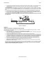
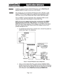
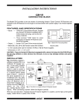
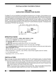
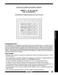
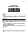
Page 1
Model MRC44CB1
INSTALLATION INSTRUCTIONS
KEYPAD
+12V GND SIG
CONTROLLER
LED1
IR IN
PWR
MODEL MRC44CB1
MRC SERIES CONNECTING BLOCK
JP1
TABLE OF CONTENTS
INTRODUCTION..................................................................................................................................................................1
Features ..........................................................................................................................................................................1
Specifications...................................................................................................................................................................1
INSTALLATION....................................................................................................................................................................2
Example A - Substituting A Smartpad3, Waterpad Keypad, or IR Receiver In Place Of A MRC44 Keypad ..........................2
Example B - Substituting A Secondary Sub-Zone MRC44 Keypad With A Smartpad3, Waterpad Keypad or IR Receiver ....2
Example C - Adding An IR Receiver To A Zone With An MRC44 Keypad...........................................................................3
Example D - Extending The Overall Length Between MRC44 Keypads..............................................................................4
TROUBLESHOOTING..........................................................................................................................................................4
INTRODUCTION
The MRC44CB1 connecting block allows added flexibility for current MRC44 system owners in regard to Keypad placement. It
also provides for the addition of external IR Receivers and/or utilizing other Xantech IR Keypads on an existing MRC44
system (i.e. using SMARTPAD3 or WATERPAD Keypads in addition to or instead of, the standard MRC Controller Keypads).
FEATURES
• Add external Xantech IR Receivers in conjunction with MRC44 Keypads
• For Retro installs requiring J-Box style keypads only, allows integration of SMARTPAD3 or WATERPAD Keypads to an
existing MRC44 system
• Add outdoor Zone or Sub-Zone utilizing WATERPAD Keypad
• Extend maximum distance of Secondary Keypad to 600ft
• External Power Supply selector jumper. Enables use of external 12v supply for longer cable runs and applications requiring
higher current capacity supplies
• IR Receive confirmation LED
SPECIFICATIONS
• 1 – Three Terminal, Screw-Type connection for +12VDC, GND, and SIGnal from Xantech IR Receivers and IR Controller
Keypads
• 1 – 3.5mm mini stereo “Quick Connect” IR IN input jack
• 2.1mm coaxial power jack
• 2 – RJ45 connectors for connection to/from MRC Controller and MRC44 Keypad
• Max Distance powered from MRC44 Controller: 200ft as measured from MRC44 Controller to last keypad/IR Receiver in
line
• Max Distance powered fro external 782-00 PS: 600ft as measured from MRC44 Controller to last keypad/IR Receiver in
line.
• Dimensions: 3-½” W x 1” D x ¾”H
© 2002 Xantech Corporation
Page 2
Model MRC44CB1
KEYPAD
+12V GND SIG
PWR
CONTROLLER
IR IN
LED1
JP1
Figure 1 - MRC44CB1 Connecting Block
INSTALLATION
Figures 2a, b, c, & d represents the different ways a MRC44CB1 can be utilized in different applications.
400 feet max (122 m)
A
POWER
1
2
3
SmartPad3 or
Waterpad
+12VDC
GND
SIG
MRC44
4
FOUR ZONE - FOUR SOURCE AUDIO/VIDEO CONTROLLER/AMPLIFIER
+12V GND SIG
781RG Power Supply
KEYPAD
IR IN
PWR
IR Receiver
CONTROLLER
LED1
JP1
MRC44CB1
Figure 2a – Example A
EXAMPLE A
SUBSTITUTING A SMARTPAD3, WATERPAD OR IR RECEIVER IN PLACE OF A MRC44 KEYPAD
This is desired if an outdoor zone keypad is required or if the keypad must be mounted in a standard J-Box
1. Remove Power Jumper (JP1) from MRC44CB1
2. Mount MRC44CB1 to a convenient location using the Adhesive strip supplied
3. Run a CAT5 jumper from the MRC44 Keypad output to the connector labeled Controller on the MRC44CB1
4. Run 3 conductor 22AWG cable (or higher) to desired keypad or IR receiver location
5. Connect one end of the 3-conductor cable to the V G S terminals of the MRC44CB1 connecting block and the other
end to the proper +12v, IR Out, and GND terminals of the desired Keypad or IR Receiver.
Note: Refer to applicable instructions supplied with Keypad or IR Receiver for proper wiring instructions.
6. Connect 781RG or 782-00 Power Supply (depending upon current load requirements) to MRC44CB1 2.5mm Coaxial
Jack
Caution! Make sure jumper JP1 On MRC44CB1 is removed before connecting Power Supply to connecting block.
200 feet max (61 m)
B
+12VDC
GND
SIG
POWER
MRC44
POWER
1
2
3
4
CH
VOL
PAUSE
FOUR ZONE - FOUR SOURCE AUDIO/VIDEO CONTROLLER/AMPLIFIER
CH
REW
SELECT
PLAY
FF
VOL
IR Receiver
STOP
MUTE
KEYPAD
+12V GND SIG
781RG Power Supply
CONTROLLER
LED1
IR IN
PWR
STATUS
SmartPad3 or
Waterpad
JP1
MRC44CB1
Figure 2b – Example B
EXAMPLE B
SUBSTITUTING A SECONDARY SUB-ZONE MRC44 KEYPAD WITH A SMARTPAD3, WATERPAD OR IR RECEIVER
This is applicable if the Sub-Zone location is outdoors, requires a J-Box style mount, or if local speaker Mute is required.
1. Mount MRC44CB1 to a convenient location using the Adhesive strip supplied
2. From Primary MRC44 Keypad, run a CAT5 wire to the secondary location.
© 2002 Xantech Corporation
Model MRC44CB1
Page 3
3.
If overall distance from MRC44 Controller to secondary zone location is less than 200ft., you may power Secondary
Keypad/IR Receiver from the Primary Keypad. In this case, install a jumper across JP1 on the MRC44CB1
Connecting block.
Note: If overall distance from MRC44 to secondary zone is greater than 200ft., an external 781RG power supply
will be required. In this case REMOVE JUMPER across JP1 on MRC44CB1 and connect supply to 2.5mm coaxial
jack.
4. Properly terminate wire with RJ45 connector and connect to the connector labeled Controller on the MRC44CB1
5. Run 3-conductor wire from MRC44CB1 Connecting block location to Secondary Keypad or IR Receiver location.
6. Connect one end of the 3-conductor cable to the V G S terminals of the MRC44CB1 connecting block and the other
end to the proper +12v, IR Out, and GND terminals of the desired Keypad or IR Receiver.
Note: If IR Receiver is being connected with a 3.5mm ‘Quick Connect’ plug, simply insert plug into jack labeled IR
IN on MRC44CB1
781RG Power Supply
IR Receiver
MRC44CB1
+12V GND SIG
KEYPAD
IR IN
PWR
C
CONTROLLER
LED1
JP1
POWER
POWER
MRC44
POWER
1
2
3
4
CH
PAUSE
VOL
CH
VOL
CH
VOL
PAUSE
FOUR ZONE - FOUR SOURCE AUDIO/VIDEO CONTROLLER/AMPLIFIER
CH
REW
SELECT
PLAY
FF
REW
STOP
STATUS
SELECT
PLAY
FF
VOL
STOP
STATUS
MUTE
MUTE
200 feet max (61 m)
Figure 2c – Example C
EXAMPLE C
ADDING AN IR RECEIVER TO A ZONE WITH A MRC44 KEYPAD
This is applicable if the IR Receiver needs to be in a different location than the Keypad/s or if a “CFL Friendly” or “Plasma
Friendly” IR Receiver is required.
1. Mount MRC44CB1 to a convenient location using the Adhesive strip supplied
2. If only one IR Receiver is to be added, you may power this from the MRC44 Controller. In this case, place a jumper
across JP1 on the MRC44CB1 connecting block.
3. From the Primary MRC44 Keypad, run a CAT5 cable to where the IR Receiver will be located.
4. Properly terminate both ends of the cable with RJ45 connectors. Plug one end into the connector labeled Expansion
on the MRC44 Keypad and the other end into the connector labeled Controller on the MRC44CB1 connecting block.
5. If IR Receiver is equipped with a “quick connect” 3.5mm connector, plug directly into the jack labeled IR IN on the
MRC44CB1. If the IR Receiver has “stripped” ends, plug the appropriate wires into the V, G, and S terminals.
6. If another MRC44 Keypad is being used, run another CAT5 cable from the MRC44CB1 connecting block to the
location of the next keypad and properly terminate both ends with RJ45 Connectors
7. Plug one end into the connector labeled Keypad on the MRC44CB1 and the other end into the connector labeled
Controller on the MRC44 Keypad
Note: If the overall distance between the MRC44 Controller and the last Keypad in the line is greater than 200ft.,
an external power supply will be needed. In this case, remove the jumper across JP1 and use a 782-00 Power
Supply connected to the MRC44CB1 connecting block.
© 2002 Xantech Corporation
Page 4
Model MRC44CB1
781RG Power Supply
IR Receiver
400 feet max (122 m)
MRC44CB1
KEYPAD
+12V GND SIG
CONTROLLER
LED1
IR IN
PWR
D
JP1
POWER
POWER
MRC44
POWER
1
2
3
4
CH
PAUSE
VOL
CH
VOL
CH
VOL
PAUSE
FOUR ZONE - FOUR SOURCE AUDIO/VIDEO CONTROLLER/AMPLIFIER
CH
REW
SELECT
PLAY
FF
REW
SELECT
PLAY
STOP
STATUS
FF
VOL
STOP
MUTE
STATUS
MUTE
600 feet max (183 m)
Figure 2d – Example D
EXAMPLE D
EXTENDING THE OVERALL LENGTH BETWEEN MRC44 KEYPADS
This is applicable when the overall distance between the MRC44 Controller and the last MRC44 Keypad in the chain is greater
than 200ft.
1. Remove the jumper across JP1 on the MRC44CB1 connecting block
2. From the Primary MRC44 Keypad, run a CAT5 to the location where the MRC44CB1 connecting block will be
located.
Note: The Primary Keypad must be within 400ft of the MRC44 Controller
3. Mount MRC44CB1 to a convenient location using the Adhesive strip supplied
4. Properly terminate both ends of the cable with RJ45 connectors. Plug one end into the connector labeled Expansion
on the MRC44 Keypad and the other end into the connector labeled Controller on the MRC44CB1 connecting block.
5. Run another CAT5 cable from the MRC44CB1 connecting block to the location of the next keypad (up to 250 ft.) and
properly terminate both ends with RJ45 Connectors
6. Plug one end into the connector labeled Keypad on the MRC44CB1 and the other end into the connector labeled
Controller on the MRC44 Keypad
7. Plug a 782-00 Power Supply into the 2.5mm Coaxial jack on the MRC44CB1 connecting block labeled PWR
CAUTION! Do not plug in a 781RG or any other Power Supply into the MRC44CB1 when a jumper is placed across JP1.
TROUBLESHOOTING
1.
2.
3.
Power Supply getting warm:
a. When using external power supply, make sure jumper is removed from JP1 on the MRC44CB1 Connecting
Block
b. Check for wiring problem either on MRC44CB1 connecting block or in RJ45 CAT5 Terminations
IR Receive Confirmation LED lights on MRC44CB1 when IR signal transmitted, but emitters do not flash at MRC44 and
no control of external sources. All control works fine when controlling from MRC44 Keypads.
a. CAT5 RJ45 connection at last keypad is plugged into EXPANSION connector instead of KEYPAD
b. Check for wiring problem either on MRC44CB1 connecting block or in RJ45 CAT5 Terminations
Still getting IR Interference even when using “CFL Friendly” or “Plasma Friendly” IR Receiver:
a. IR Receiver on MRC44 Keypads needs to be disabled. Remove jumper across Sensor Enable pins on rear of
MRC44 Keypad (refer to MRC44 Instruction Manual)
b. Check for wiring problem either on MRC44CB1 connecting block or in RJ45 CAT5 Terminations or interference
from adjacent cable runs, Dimmer Controls etc.
XANTECH CORPORATION
12950 Bradley Avenue, Sylmar CA 91342-3829
phone 818.362.0353 • fax 818.362.9506
Part No. 08901185 Rev B 09-04-2003