1
BD9:AB&%..
&%M '+
7:C8=IDEA6I=:
DLC:GHB6CJ6A
;DGBD9:AHB6CJ;68IJG:9H>C8:-$%,
E]dcZ/(+%,()"()-'Dca^cZIZX]c^XVaHjeedgi/iZX]"hjeedgi5h]de[dm#W^o
8DENG><=I;:7GJ6GN!'%%,7NLDD9HID8@>CI:GC6I>DC6A!>C8#!G:K>H:96EG>A!'%&&7AIH
.%*'8G
L6GC>C</CDEDGI>DCD;I=>HB6CJ6AB6N7:G:EGD9J8:9>C6CNH=6E:DG;DGBL>I=DJI
I=:LG>II:C6EEGDK6AD;LDD9HID8@>CI:GC6I>DC6A!>C8#
Eg^ciZY^c8]^cV
K_`jdXelXcgifm`[\jZi`k`ZXcjX]\kp`ejkilZk`fejfek_\gifg\ij\klg#
fg\iXk`fe#dX`ek\eXeZ\#Xe[j\im`Z\f]k_`jdXZ_`e\&kffc%JXm\k_`j
[fZld\ek#i\]\ikf`kf]k\e#Xe[lj\`kkf`ejkilZkfk_\ifg\iXkfij%
=X`cli\kfi\X[#le[\ijkXe[Xe[]fccfnk_\`ejkilZk`fej`ek_`jdXelXc
dXpi\jlck`e]`i\fij\i`fljg\ijfeXc`ealipÇ`eZcl[`e^XdglkXk`fe#
\c\ZkifZlk`fe#fi[\Xk_%
K_\fne\if]k_`jdXZ_`e\&kffc`jjfc\cpi\jgfej`Yc\]fi`kjjX]\lj\%
K_`ji\jgfej`Y`c`kp`eZcl[\jYlk`jefkc`d`k\[kfgifg\i`ejkXccXk`fe`e
XjX]\\em`ifed\ek#g\ijfee\ckiX`e`e^Xe[ljX^\Xlk_fi`qXk`fe#
gifg\i`ejg\Zk`feXe[dX`ek\eXeZ\#dXelXcXmX`cXY`c`kpXe[Zfdgi\$
_\ej`fe#Xggc`ZXk`fef]jX]\kp[\m`Z\j#Zlkk`e^&jXe[`e^&^i`e[`e^kffc
`ek\^i`kp#Xe[k_\ljX^\f]g\ijfeXcgifk\Zk`m\\hl`gd\ek%
K_\dXel]XZkli\in`ccefkY\_\c[c`XYc\]fi`ealipfigifg\ikp
[XdX^\]ifde\^c`^\eZ\#`dgifg\ikiX`e`e^#dXZ_`e\df[`]`ZXk`fejfi
d`jlj\%
Jfd\[ljkZi\Xk\[Ypgfn\ijXe[`e^#jXn`e^#^i`e[`e^#[i`cc`e^#Xe[
fk_\iZfejkilZk`feXZk`m`k`\jZfekX`ejZ_\d`ZXcjbefnekfk_\JkXk\f]
:Xc`]fie`XkfZXlj\ZXeZ\i#Y`ik_[\]\Zkjfifk_\ii\gif[lZk`m\_Xid%
Jfd\\oXdgc\jf]k_\j\Z_\d`ZXcjXi\1
C\X[]ifdc\X[$YXj\[gX`ekj%
:ipjkXcc`e\j`c`ZX]ifdYi`Zbj#Z\d\ekXe[fk_\idXjfeipgif[lZkj%
8ij\e`ZXe[Z_ifd`ld]ifdZ_\d`ZXccp$ki\Xk\[cldY\i%
Pflii`jb]ifdk_\j\\ogfjli\jmXi`\j#[\g\e[`e^fe_fnf]k\epfl
[fk_`jkpg\f]nfib%Kfi\[lZ\pfli\ogfjli\kfk_\j\Z_\d`ZXcj1
Nfib`eXn\ccm\ek`cXk\[Xi\X#Xe[nfibn`k_Xggifm\[jX]\kp\hl`g$
d\ek#jlZ_Xjk_fj\[ljkdXjbjk_XkXi\jg\Z`Xccp[\j`^e\[kf]`ck\i
flkd`ZifjZfg`ZgXik`Zc\j%
J8=<KP%%%%%%%%%%%%%%%%%%%%%%%%%%%%%%%%%%%%%%%%%%%%%%%Standard Machinery Safety Instructions ...... 6
Additional Safety Instructions for Lathes .... 8
J<IM@:<%%%%%%%%%%%%%%%%%%%%%%%%%%%%%%%%%%%%%%%%%%%% *,
Troubleshooting................................. 35
Cross Slide Backlash Adjustment ............ 37
Gib Adjustments ................................ 37
Electrical Component Connections .......... 38
Wiring Diagram ................................. 39
<C<:KI@:8C%%%%%%%%%%%%%%%%%%%%%%%%%%%%%%%%%%%%%%%%%0
Circuit Requirements ............................ 9
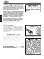
Grounding Requirements ...................... 10
Extension Cords ................................ 10
N8II8EKP%%%%%%%%%%%%%%%%%%%%%%%%%%%%%%%%%%%%%%%% ,,
D8@EK<E8E:<
J<IM@:<
G8IKJ
LJ<K?<HL@:B>L@;<G8><C89<CJKFJ<8I:?FLK@E=FID8K@FE=8JK
FG<I8K@FEJ
FG<I8K@FEJ%%%%%%%%%%%%%%%%%%%%%%%%%%%%%%%%%%%%%%% (,
General .......................................... 15
Power Control................................... 15
Mounting Chuck or Faceplate ................ 16
Replacing Jaws ................................. 17
Four-Jaw Chuck ................................ 18
Faceplate ........................................ 19
Tailstock ......................................... 20
Drilling With the Tailstock .................... 20
Cutting Shallow Tapers with Tailstock ...... 21
Aligning Tailstock .............................. 22
Centers........................................... 23
Steady Rest ...................................... 24
Follow Rest ...................................... 24
Compound Rest ................................. 25
Tool Post ......................................... 25
Manual Feed Handwheels ..................... 26
Determining Correct Spindle RPM ........... 27
Spindle RPM ..................................... 28
Power Feed Rate ............................... 29
Inch Threads .................................... 30
Metric Threads .................................. 31
J<KLG
J<KLG%%%%%%%%%%%%%%%%%%%%%%%%%%%%%%%%%%%%%%%%%%%%%% ((
Unpacking ....................................... 11
Inventory ........................................ 11
Machine Placement ............................ 12
Cleaning Machine............................... 12
Test Run & Break-In ............................ 13
G8IKJ%%%%%%%%%%%%%%%%%%%%%%%%%%%%%%%%%%%%%%%%%%%%%% +'
Spindle and Drive Belt......................... 40
Apron ............................................. 42
Apron Parts ...................................... 43
Tool Holder and Compound Rest ............. 44
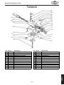
Tailstock ......................................... 45
Bed and Leadscew ............................. 46
Steady Rest and Follow Rest ................. 47
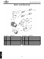
Motor and Electrical ........................... 48
Gearbox Diagram A............................. 49
Gearbox Diagram B ............................ 51
Cross Feed and Carriage ...................... 53
<C<:KI@:8C
D8@EK<E8E:<%%%%%%%%%%%%%%%%%%%%%%%%%%%%%%%%%%%% *)
Basic Maintenance ............................. 32
General Lubrication............................ 32
Belt Adjustment or Replacement ............ 34
J8=<KP
@EKIF;L:K@FE%%%%%%%%%%%%%%%%%%%%%%%%%%%%%%%%%%%%%)
Woodstock Technical Support .................. 2
Machine Specifications .......................... 3
Identification ..................................... 5
@EKIF;L:K@FE
KXYc\f]:fek\ekj
@EKIF;L:K@FE
Df[\cD('00D]^J`eZ\/&'.
@EKIF;L:K@FE
Nff[jkfZbK\Z_e`ZXcJlggfik
Your new E:AB8AJ® Model M1099 Benchtop Lathe has been specially designed to provide many years
of trouble-free service. Close attention to detail, ruggedly built parts and a rigid quality control program
assure safe and reliable operation.
Woodstock International, Inc. is committed to customer satisfaction. Our intent with this manual is to
include the basic information for safety, setup, operation, maintenance, and service of this product.
We stand behind our machines! In the event that questions arise about your machine, please contact
Woodstock International Technical Support at (360) 734-3482 or send e-mail to: k\Z_$jlggfik7j_fg]fo%
Y`q. Our knowledgeable staff will help you troubleshoot problems and process warranty claims.
If you need the latest edition of this manual, you can download it from _kkg1&&nnn%j_fg]fo%Y`q.
If you have comments about this manual, please contact us at:
Nff[jkfZb@ek\ieXk`feXc#@eZ%
8kke1K\Z_e`ZXc;fZld\ekXk`feDXeX^\i
G%F%9fo)*'0
9\cc`e^_Xd#N80/)).
<dX`c1dXelXcj7nff[jkfZb`ek%Zfd
-2-
@EKIF;L:K@FE
Df[\cD('00D]^J`eZ\/&'.
02'(/0
6+23)2;;%(1&+/$7+(
"#$$%'%
*+ *
/ /
;
<= ><
?@K
$ >*N
Q%= + $VX
V Z%
+[V ;K\]
XV+$ @>
+[$ >;\]
+[ >;\]
^=%=VN \]
$=% ;\@
$ @@;\@
$ >;\@
V N ;\_
`_
]
Q%= >
KK>?@@@_
V z{% @;\@
z `
-3-
@EKIF;L:K@FE
Df[\cD('00D]^J`eZ\/&'.
Q%=Z%# Z%# @|
Q%=' ' ]|?@'
Q%= @>
@K|K
V} >;\]
Z+X= \_
Z+' @
Z+Z #N @
*z $'
*z~ V *$'
V $'
"^
} };;^X;;z^* K^@^>;K\]
#Z^} K;\@^@;\@
}$
$ } _?K
Z^}^* >@^@^@
+%= /;>*N
=%=$%N @<
+ %V%
+/ /
$Z K
$~% _~%
%'%
'%% Q"<K;K
$%[[ $
} @
Q%=Z XZ*z
<== *%
*~%/;}
$'%
Vz
#%#%$<<=%<%$%#
ZV<==@>V+$%
-4-
@EKIF;L:K@FE
Df[\cD('00D]^J`eZ\/&'.
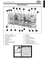
@[\ek`]`ZXk`fe
D
A
B
E
F
J
I
G
C
H
K
U
T
8%
9%
:%
;%
<%
=%
>%
?%
@%
A%
B%
S
R
O
Q
N
P
C%
D%
E%
F%
G%
H%
I%
J%
K%
L%
Emergency Stop Button
Motor Direction Selector Knob
Power ON Push Button
3-Jaw Chuck
Steady Rest
4-Way Tool Holder
Follow Rest
Compound Feed Handwheel
Tailstock Barrel Lock Lever
Tailstock
Back Splash
L
Chip Tray
Thread Dial
Half Nut Lever
Cross Feed Handwheel
Carriage Feed Handwheel
Lead Screw
Threading Dial (Alpha)
Gearbox Oil Level Sight Glass
Threading Dial (Numeric)
Change Gear and Belt Safety Cover
I<8;Xe[le[\ijkXe[k_`j
\ek`i\ `ejkilZk`fe dXelXc
Y\]fi\lj`e^k_\dXZ_`e\%
J\i`flj g\ijfeXc `ealip
dXp fZZli `] jX]\kp Xe[
fg\iXk`feXc`e]fidXk`fe`j
efk le[\ijkff[ Xe[ ]fc$
cfn\[% ;F EFK i`jb pfli
jX]\kpYpefki\X[`e^
-5-
M
Df[\cD('00D]^J`eZ\/&'.
J8=<KP
J8=<KP
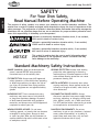
For Your Own Safety,
Read Manual Before Operating Machine
K_\ gligfj\ f] jX]\kp jpdYfcj `j kf XkkiXZk pfli Xkk\ek`fe kf gfjj`Yc\ _XqXi[flj Zfe[`k`fej% K_`j
dXelXclj\jXj\i`\jf]jpdYfcjXe[j`^eXcnfi[j`ek\e[\[kfZfem\pk_\c\m\cf]`dgfikXeZ\f]k_\
jX]\kpd\jjX^\j%K_\gif^i\jj`fef]jpdYfcj`j[\jZi`Y\[Y\cfn%I\d\dY\ik_XkjX]\kpd\jjX^\jYp
k_\dj\cm\j [f efk \c`d`eXk\ [Xe^\i Xe[ Xi\ efk X jlYjk`klk\ ]fi gifg\i XZZ`[\ek gi\m\ek`fe d\X$
jli\jÇk_`ji\jgfej`Y`c`kp`jlck`dXk\cplgkfk_\fg\iXkfi
@e[`ZXk\jXe`dd`e\ekcp_XqXi[fljj`klXk`fen_`Z_#`]efkXmf`[\[#
N@CCi\jlck`e[\Xk_fij\i`flj`ealip%
@e[`ZXk\jXgfk\ek`Xccp_XqXi[fljj`klXk`fen_`Z_#`]efkXmf`[\[#
:FLC;i\jlck`e[\Xk_fij\i`flj`ealip%
@e[`ZXk\jXgfk\ek`Xccp_XqXi[fljj`klXk`fen_`Z_#`]efkXmf`[\[#
D8Pi\jlck`ed`efifidf[\iXk\`ealip%
EFK@:<
K_`jjpdYfc`jlj\[kfXc\ikk_\lj\ikflj\]lc`e]fidXk`feXYflk
gifg\ifg\iXk`fef]k_\\hl`gd\ek#Xe[&fiXj`klXk`fek_XkdXp
ZXlj\[XdX^\kfk_\dXZ_`e\ip%
JkXe[Xi[DXZ_`e\ipJX]\kp@ejkilZk`fej
FNE<IËJD8EL8C% Read and understand this
owner’s manual BEFORE using machine.
Untrained users can be seriously hurt.
?<8I@E>GIFK<:K@FE% Always wear hearing
protection when operating or observing
loud machinery. Extended exposure to this
noise without hearing protection can cause
permanent hearing loss.
<P<GIFK<:K@FE% Always wear ANSI-approved
safety glasses or a face shield when operating
or observing machinery to reduce the risk of
eye injury or blindness from flying particles.
Everyday eyeglasses are not approved safety
glasses.
D<EK8C8C<IKE<JJ% Be mentally alert when
running machinery. Never operate under the
influence of drugs or alcohol, when tired, or
when distracted.
?8Q8I;FLJ;LJK% Dust created while using
machinery may cause cancer, birth defects,
or long-term respiratory damage. Be aware
of dust hazards associated with workpiece
materials, and always wear a NIOSH-approved
respirator to reduce your risk.
;@J:FEE<:K@E>GFN<IJLGGCP% Always
disconnect machine from power supply before
servicing, adjusting, or changing cutting tools
(bits, blades, cutters, etc.). Make sure switch
is in OFF position before reconnecting to avoid
an unexpected or unintentional start.
N<8I@E>GIFG<I8GG8I<C% Do not wear
clothing, apparel, or jewelry that can become
entangled in moving parts. Always tie back
or cover long hair. Wear non-slip footwear to
avoid accidental slips which could cause a loss
of workpiece control.
;8E><IFLJ<EM@IFED<EKJ% Do not use
machinery in wet or rainy locations, cluttered
areas, around flammables, or in poorly-lit
areas. Keep work area clean, dry, and welllighted to minimize risk of injury.
-6-
Df[\cD('00D]^J`eZ\/&'.
JK89C<D8:?@E<% Unexpected movement during
operations greatly increases the risk of injury
and loss of control. Verify machines are
stable/secure and mobile bases (if used) are
locked before starting.
=FI:@E>D8:?@E<IP% Do not force machine. It
will do the job safer and better at the rate for
which it was designed.
FECPLJ<8J@EK<E;<;% Only use machine for
its intended purpose. Never modify or alter
machine for a purpose not intended by the
manufacturer or serious injury may result!
8NBN8I;GFJ@K@FEJ% Keep proper footing and
balance at all times when operating machine.
Do not overreach! Avoid awkward hand
positions that make workpiece control difficult
or increase the risk of accidental injury.
LJ<I<:FDD<E;<;8::<JJFI@<J% Consult
this owner’s manual or the manufacturer for
recommended accessories. Using improper
accessories will increase the risk of serious
injury.
LE8KK<E;<;FG<I8K@FE% Never leave machine
running while unattended. Turn machine off
and ensure all moving parts completely stop
before walking away.
:?@C;I<E9PJK8E;<IJ% Keep children and
bystanders a safe distance away from work
area. Stop using machine if children or
bystanders become a distraction.
D8@EK8@EN@K?:8I<% Follow all maintenance
instructions and lubrication schedules to
keep machine in good working condition. An
improperly maintained machine may increase
the risk of serious injury.
I<DFM<8;ALJK@E>KFFCJ% Never leave
adjustment tools, chuck keys, wrenches, etc.
in or on machine—especially near moving
parts. Verify removal before starting!
:?<:B;8D8><;G8IKJ% Regularly inspect
machine for damaged parts, loose bolts,
mis-adjusted or mis-aligned parts, binding,
or any other conditions that may affect safe
operation. Always repair or replace damaged
parts, wires, cords, or plugs before operating
machine.
J<:LI@E>NFIBG@<:<% When required, use
clamps or vises to secure workpiece. A secured
workpiece protects hands and frees both of
them to operate the machine.
=<<;;@I<:K@FE% Unless otherwise noted, feed
work against the rotation of blades or cutters.
Feeding in the same direction of rotation may
pull your hand into the cut.
D8@EK8@EGFN<I:FI;J%When disconnecting
cord-connected machines from power, grab
and pull the plug—NOT the cord. Pulling the
cord may damage the wires inside. Do not
handle the cord/plug with wet hands. Avoid
cord damage by keeping it away from heated
surfaces, high traffic areas, harsh chemicals,
and wet or damp locations.
>L8I;J:FM<IJ% Guards and covers can
protect you from accidental contact with
moving parts or flying debris. Make sure
they are properly installed, undamaged, and
working correctly before using machine.
<OG<I@<E:@E>;@==@:LCK@<J% If at any time you
are experiencing difficulties performing the
intended operation, stop using the machine!
Contact our Technical Support for help at
(360) 734-3482.
E<M<IJK8E;FED8:?@E<% Serious injury or
accidental contact with cutting tool may
occur if machine is tipped. Machine may be
damaged.
-7-
J8=<KP
8GGIFM<;FG<I8K@FE% Untrained operators
can be seriously hurt by machinery. Only
allow trained or properly supervised people
to use machine. When machine is not being
used, disconnect power, remove switch keys,
or lock-out machine to prevent unauthorized
use—especially around children. Make
workshop kid proof!
Df[\cD('00D]^J`eZ\/&'.
J8=<KP
8[[`k`feXcJX]\kp@ejkilZk`fej]fiCXk_\j
:C<8I@E> :?@GJ% Metal chips can easily cut bare
skin—even through a piece of cloth. Avoid clearing chips by hand or with a rag. Use a brush or
vacuum to clear metal chips.
J8=< :C<8I8E:<J% Workpieces that crash into
other components on the lathe may throw dangerous projectiles in all directions, leading to
impact injury and damaged equipment. Before
starting the spindle, make sure the workpiece
has adequate clearance by hand-rotating it
through its entire range of motion. Also, check
the tool and tool post clearance, chuck clearance, and saddle clearance.
:?L:B B<P J8=<KP% A chuck key left in the
chuck can become a deadly projectile when the
spindle is started. Always remove the chuck key
after using it. Develop a habit of not taking your
hand off of a chuck key unless it is away from
the chuck.
I<DFM@E>&@EJK8CC@E> :?L:BJ% Chucks are
heavy and often oily and slippery to hold. Losing
your grip on a chuck can lead to crushed hands
or amputated fingers. To reduce this risk and
protect the lathe bed, cover the bed with a
sheet of wood and use a chuck cradle. For large
chucks, also get the assistance of one or more
people, and use an appropriate hoisting apparatus when installing or removing.
KFFCJ<C<:K@FE% Cutting with an incorrect or dull
tool bit will often overload the bit and cause it
to dig into the workpiece and snap. As a result,
hot razor-sharp shards may be ejected that can
result in a burn or blinding injury. To increase
safety, decrease tool bit load, and provide the
best finish possible, always use the correct tool
and one that is sharp.
J<:LI@E> NFIBG@<:<% A thrown workpiece may
cause severe injury or even death. When swapping the chuck jaw positions, double-check that
the jaw fasteners are tight and that the top jaw
is fully seated with the lower jaw no gaps exist
between the two. When clamping a workpiece,
maximum gripping force is attained at full jaw
and scroll gear engagement. If jaw and scroll
gear are only partially engaged, clamping force
is reduced.
JG<<; I8K<J% Operating the lathe at the wrong
speed can cause nearby parts to break or the
workpiece to come loose, which will result in
dangerous projectiles that could cause severe
impact injury. Large workpieces must be turned
at slow speeds. Always use the appropriate feed
and speed rates.
JKFGG@E> JG@E;C< 9P ?8E;% Stopping the spindle by putting your hand on the workpiece or
chuck creates an extreme risk of entanglement,
impact, crushing, friction, or cutting hazards.
Never attempt to slow or stop the lathe spindle
with your hand. Allow the spindle to come to a
stop on its own or use the brake (if equipped).
:I8J?<J% Tooling or components that contact a
spinning chuck may shatter sending metal fragments in all directions resulting in severe impact
injuries and major damage to the lathe. Reduce
this risk by releasing automatic feeds after use
and checking clearances before starting the
lathe.
CFE> JKF:B J8=<KP% Long stock can whip violently if not properly supported, causing serious
impact injury and damage to the lathe. Reduce
this risk by supporting any stock that extends
from the chuck/headstock more than three
times its own diameter. Always turn long stock
at slow speeds.
:LKK@E> =CL@; J8=<KP% Contaminated cutting
fluid is a toxic biohazard that can cause poisoning from skin contact. Incorrectly positioned
cutting fluid nozzles can splash on the operator
or the floor, resulting in an exposure or slipping
hazard. To decrease your risk, change cutting
fluid regularly and use the system carefully.
-8-
Df[\cD('00D]^J`eZ\/&'.
<C<:KI@:8C
:`iZl`kI\hl`i\d\ekj
This machine must be connected to the correct size and
type of power supply circuit, or fire or electrical damage
may occur. Read through this section to determine if an
adequate power supply circuit is available. If a correct
circuit is not available, a qualified electrician MUST install
one before you can connect the machine to power.
=lcc$CfX[:lii\ekIXk`e^
The full-load current rating is the amperage a machine
draws at 100% of the rated output power. On machines
with multiple motors, this is the amperage drawn by the
largest motor or sum of all motors and electrical devices
that might operate at one time during normal operations.
=lcc$CfX[:lii\ekIXk`e^Xk(('M%%%%%%%%%%%%%%%%(*%-8dgj
This machine is prewired to operate on a 110V power
supply circuit that has a verified ground and meets the
following requirements:
:`iZl`kKpg\%%%%%%%%%%%%%%% (('M&()'M#-'?q#J`e^c\$G_Xj\
:`iZl`kJ`q\%%%%%%%%%%%%%%%%%%%%%%%%%%%%%%%%%%%%%%%%%%%%% (,8dgj
Gcl^&I\Z\gkXZc\%%%%%%%%%%%%%%%%%%%%%%%%%%%%%%%%%%%% E<D8,$(,
-9-
@eZfii\Zkcp n`i`e^ fi ^ifle[`e^ k_`j
dXZ_`e\ZXeZXlj\\c\ZkifZlk`fe#]`i\#
fidXZ_`e\[XdX^\%Kfi\[lZ\k_`ji`jb#
fecp X hlXc`]`\[ \c\Zki`Z`Xe fi j\im`Z\
g\ijfee\c j_flc[ [f Xep i\hl`i\[
\c\Zki`ZXcnfib]fik_`jdXZ_`e\%
EFK@:<
K_\ Z`iZl`k i\hl`i\d\ekj c`jk\[ `e k_`j
dXelXc Xggcp kf X [\[`ZXk\[ Z`iZl`kÇ
n_\i\fecpfe\dXZ_`e\n`ccY\ilee`e^
Xk X k`d\% @] k_`j dXZ_`e\ n`cc Y\
Zfee\Zk\[ kf X j_Xi\[ Z`iZl`k n_\i\
dlck`gc\ dXZ_`e\j n`cc Y\ ilee`e^ Xk
k_\ jXd\ k`d\# Zfejlck X hlXc`]`\[
\c\Zki`Z`Xekf\ejli\k_Xkk_\Z`iZl`k`j
gifg\icpj`q\[]fijX]\fg\iXk`fe%
<C<:KI@:8C
A power supply circuit includes all electrical equipment
between the breaker box or fuse panel in the building
and the machine. The power supply circuit used for
this machine must be sized to safely handle the fullload current drawn from the machine for an extended
period of time. (If this machine is connected to a circuit
protected by fuses, use a time delay fuse marked D.)
K_\ dXZ_`e\ dljk Y\ gifg\icp j\k lg
Y\]fi\ `k `j jX]\ kf fg\iXk\% ;F EFK
Zfee\Zk k_`j dXZ_`e\ kf k_\ gfn\i
jfliZ\ lek`c `ejkilZk\[ kf [f cXk\i `e
k_`jdXelXc%
Df[\cD('00D]^J`eZ\/&'.
>ifle[`e^I\hl`i\d\ekj
<C<:KI@:8C
This machine MUST be grounded. In the event of certain
types of malfunctions or breakdowns, grounding provides
a path of least resistance for electric current to travel—in
order to reduce the risk of electric shock.
Improper connection of the equipment-grounding wire will
increase the risk of electric shock. The wire with green
insulation (with/without yellow stripes) is the equipmentgrounding wire. If repair or replacement of the power
cord or plug is necessary, do not connect the equipmentgrounding wire to a live (current carrying) terminal.
K_\ dXZ_`e\ dljk Y\ gifg\icp j\k lg
Y\]fi\ `k `j jX]\ kf fg\iXk\% ;F EFK
Zfee\Zk k_`j dXZ_`e\ kf k_\ gfn\i
jfliZ\ lek`c `ejkilZk\[ kf [f cXk\i `e
k_`jdXelXc%
Check with a qualified electrician or service personnel
if you do not understand these grounding requirements,
or if you are in doubt about whether the tool is
properly grounded. If you ever notice that a cord or
plug is damaged or worn, disconnect it from power, and
immediately replace it with a new one.
=fi(('M:fee\Zk`fe
The plug provided with the machine has a ground prong
that must be attached to the equipment-grounding wire
inside the included power cord. The plug must only be
inserted into a matching receptacle that is properly
installed and grounded in accordance with all local codes
and ordinances.
GROUNDED
5-15 RECEPTACLE
<gdjcY^c\Egdc\
5-15 PLUG
<ok\ej`fe:fi[j
CZjigVa =di
We do not recommend using an extension cord with this
machine. Extension cords cause voltage drop, which may
damage electrical components and shorten motor life.
Voltage drop increases with longer extension cords and
the gauge smaller gauge sizes (higher gauge numbers
indicate smaller sizes).
Any extension cord used with this machine must contain a
ground wire, match the required plug and receptacle, and
meet the following requirements:
D`e`dld>Xl^\J`q\Xk))'M%%%%%%%%%%%%%%%%%%%%%% ()8N>
DXo`dldC\e^k_J_fik\i`j9\kk\i %%%%%%%%%%%%%%%%,']k%
-10-
=`^li\1% NEMA 5-15 plug & receptacle.
;F EFK df[`]p k_\ gifm`[\[ gcl^ fi
lj\ Xe X[Xgk\i `] k_\ gcl^ n`cc efk ]`k
pfli i\Z\gkXZc\% K_`j `j Xe `e[`ZXk`fe
k_Xk pfli gfn\i jlggcp Z`iZl`k [f\j
EFK d\\k k_\ i\hl`i\d\ekj ]fi k_\
dXZ_`e\2 _Xm\ Xe \c\Zki`Z`Xe `ejkXcc
k_\ Zfii\Zk gfn\i jlggcp Z`iZl`k% @]
k_\ dXZ_`e\ dljk Y\ i\Zfee\Zk\[ ]fi
lj\ fe X [`]]\i\ek kpg\ f] \c\Zki`Z
Z`iZl`k# k_\ i\Zfee\Zk`fe j_flc[ Y\
dX[\ Yp X hlXc`]`\[ \c\Zki`Z`Xe fi
j\im`Z\ g\ijfee\c2 X]k\i i\Zfee\Zk`fe#
k_\dXZ_`e\dljkZfdgcpn`k_XcccfZXc
Zf[\jXe[fi[`eXeZ\j%
Df[\cD('00D]^J`eZ\/&'.
J<KLG
LegXZb`e^
This machine has been carefully packaged for safe
transportation. If you notice the machine has been
damaged during shipping, please contact your authorized
Shop Fox dealer immediately.
Jfd\_Xi[nXi\&]Xjk\e\ijfek_\`em\e$
kfip c`jk dXp Xii`m\ gi\$`ejkXcc\[ fe
k_\ dXZ_`e\% :_\Zb k_\j\ cfZXk`fej
Y\]fi\ Xjjld`e^ k_Xk Xep `k\dj ]ifd
k_\`em\ekfipc`jkXi\d`jj`e^%
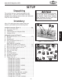
@em\ekfip
After all the parts have been removed from your
shipment, you should have the following items:
A
B
C
D
GXZbX^\[8ZZ\jjfi`\j=`^li\)
<% Hex Wrench Set (2.5, 3, 4, 5, 6 mm) ............. 1 EA
=% Tool Box .................................................... 1
>% Faceplate (8") ............................................. 1
?% Four-Jaw Universal Chuck (61⁄2") ...................... 1
@% Low Range Belt ........................................... 1
High Range Belt (Installed) ............................. 1
A% Phillips and Standard #2 Screwdriver ............. 1 EA
B% Wrench Set (12/14, 12/14, 19/17 mm) ............1 EA
C% Three-Jaw Chuck Internal Jaw Set .................... 1
D% Three-Jaw Chuck Key .................................... 1
E% Four-Jaw Chuck Key...................................... 1
F% Oil Bottle .................................................. 1
G% Cross Feed Handle........................................ 1
H% Carriage Feed Handle .................................... 1
I% Dead Center MT#3 ....................................... 1
J% Change Gear Set .......................................... 1
·8]Vc\Z<ZVg',"iddi]!>chiVaaZY#########################&
·8]Vc\Z<ZVg(+"iddi]########################################&
·8]Vc\Z<ZVg)%"iddi]########################################&
·8]Vc\Z<ZVg))"iddi]########################################&
·8]Vc\Z<ZVg)+"iddi]########################################&
·8]Vc\Z<ZVg)-"iddi]!>chiVaaZY#########################&
·8]Vc\Z<ZVg*'"iddi]########################################&
·8]Vc\Z<ZVg)*"iddi]########################################&
·8]Vc\Z<ZVg*+"iddi]!>chiVaaZY#########################&
·8]Vc\Z<ZVg+%"iddi]########################################&
·EaVhi^X9g^kZ<ZVg+%"iddi]!>chiVaaZY#################&
·8]Vc\Z<ZVg&%)"iddi]!>chiVaaZY#######################&
·8]Vc\Z<ZVg&'%"iddi]######################################&
·8]Vc\Z<ZVg&',"iddi]!>chiVaaZY#######################&
-11-
J<KLG
@ejkXcc\[8ZZ\jjfi`\j=`^li\( %%%%%%%%%%%%%%%%%%%%%%%%%Hkp%
8% Three-Jaw Chuck (5") .................................... 1
9% Steady Rest ................................................ 1
:% 4-Way Tool Post and Compound Rest .................. 1
;% Compound Slide........................................... 1
=`^li\(% Installed accessories.
E
H
F
G
I
M
J
K
L
N
O
P
Q
R
S
=`^li\)% Packaged accessories.
Df[\cD('00D]^J`eZ\/&'.
J<KLG
DXZ_`e\GcXZ\d\ek
NfibY\eZ_CfX[1 This machine distributes
a heavy load in a small footprint. Some
workbenches may require additional bracing
to support both machine and workpiece.
Nfib`e^:c\XiXeZ\j1 Consider existing and
anticipated needs, size of material to be
processed through the machine, and space
for auxiliary stands, work tables or other
machinery when establishing a location for
your Machine Type.
C`^_k`e^1 Lighting should be bright enough
to eliminate shadow and prevent eye strain.
<c\Zki`ZXc1Electrical circuits must be
dedicated or large enough to handle
amperage requirements. Outlets must be
located near each machine, so power or
extension cords are clear of high-traffic
areas. Follow local electrical codes for
proper installation of new lighting, outlets,
or circuits.
:c\Xe`e^DXZ_`e\
The bed and other unpainted parts of your lathe
are coated with a waxy grease that protects
them from corrosion during shipment. Clean this
grease off with a solvent cleaner or citrus-based
degreaser. DO NOT use chlorine-based solvents
such as brake parts cleaner or acetone—if you
happen to splash some onto a painted surface,
you will ruin the finish.
E<M<IZc\Xen`k_^Xjfc`e\
fi fk_\i g\kifc\ld$
YXj\[jfcm\ekj%Dfjk_Xm\
cfn ]cXj_ gf`ekj# n_`Z_
dXb\ k_\d \oki\d\cp
]cXddXYc\% 8 i`jb f]
\ogcfj`fe Xe[ Ylie`e^
\o`jkj `] k_\j\ gif[lZkj
Xi\lj\[%J\i`fljg\ijfeXc
`ealip dXp fZZli `] k_`j
nXie`e^`j`^efi\[
8CN8PJ nfib `e n\cc$
m\ek`cXk\[Xi\Xj]Xi]ifd
gfjj`Yc\ `^e`k`fe jfliZ\j
n_\e lj`e^ jfcm\ekj kf
Zc\Xe dXZ_`e\ip% DXep
jfcm\ekj Xi\ kfo`Z n_\e
`e_Xc\[ fi `e^\jk\[% Lj\
ZXi\ n_\e [`jgfj`e^
f] nXjk\ iX^j Xe[
kfn\cj kf Y\ jli\ k_\p
;F EFK Zi\Xk\ ]`i\ fi
\em`ifed\ekXc_XqXi[j%
LJ< _\cg\ij fi gfn\i
c`]k`e^ \hl`gd\ek kf
c`]k k_`j DXZ_`e\ EXd\%
Fk_\in`j\# j\i`flj g\i$
jfeXc`ealipdXpfZZli%
D8B< pfli j_fg ÈZ_`c[
jX]\%É <ejli\ k_Xk pfli
nfibgcXZ\ `j `eXZZ\jj`Yc\
kf Z_`c[i\e Yp Zcfj`e^ Xe[
cfZb`e^Xcc\ekiXeZ\jn_\e
pflXi\XnXp%E<M<IXccfn
lekiX`e\[ m`j`kfij `e pfli
j_fg n_\e Xjj\dYc`e^#
X[aljk`e^ fi fg\iXk`e^
\hl`gd\ek%
-12-
Df[\cD('00D]^J`eZ\/&'.
K\jkIle9i\Xb$@e
The purpose of the test run is to make sure the lathe and
safety features operate correctly before proceeding with
additional setup.
KfY\^`ek_\k\jkileYi\Xb$`egifZ\[li\#[fk_\j\
jk\gj1
Make sure the lathe is lubricated and the headstock
oil level is full. Refer to >\e\iXcClYi`ZXk`fe on
GX^\*).
)%
Make sure the chuck is correctly secured to the spindle. Refer to Dflek`e^:_lZbXe[=XZ\gcXk\ on GX^\
(- for details.
*%
Change the belt position so the spindle will rotate at
150 RPM, and disengage the half nut with the lever
shown in =`^li\*. Refer to ;\k\id`e`e^:fii\Zk
Jg`e[c\IGD on GX^\).for clarification.
+%
Rotate the red emergency stop button (=`^li\+)
clockwise so it pops out, and make sure the motor
direction selector points to STOP.
,%
Half-Nut Lever Pulled Up
(Disengaged)
=`^li\*% Half nut lever in the disengaged
position.
Move the numeric gearbox dial to ;, and the alpha
gearbox dial to 5 (see =`^li\+).
Emergency Stop Button
Efk\1 PfldXp_Xm\kfjc`^_kcpifkXk\k_\Z_lZbYp
_Xe[kf\e^X^\k_\^\Xij%
-%
Push the green power button, then turn the motor
direction dial to FWD. The top of the chuck should
now be turning toward you.
.%
Push the emergency stop button. The lathe
should stop. If not, disconnect power and refer to
KiflYc\j_ffk`e^ on GX^\*,.
/%
Return the motor direction dial to STOP, reset the
emergency stop button, restart the lathe, and let
the lathe run for a minimum of 10 minutes.
— If you hear squealing or grinding noises, turn the
lathe F== immediately and correct any problem
before further operation.
— If the problem is not readily apparent, refer to
KiflYc\j_ffk`e^ on GX^\*,.
-13-
Numeric
Dial
Motor Direction Selector
Pointing to STOP
Alpha
Dial
=`^li\+% Headstock and gearbox controls.
J<KLG
(%
DXb\ jli\ k_\ _Xc] elk c\m\i `j
[`j\e^X^\[Y\]fi\pfljkXikk_\cXk_\
K_fifl^_cp]Xd`c`Xi`q\pflij\c]n`k_Xcc
k_\ZfekifcjXe[k_\`i]leZk`fejY\]fi\
lj`e^ k_\ cfe^`kl[`eXc ]\\[ E<M<I
J?@=KC8K?<><8IJN?<ED8:?@E<@J
FG<I8K@E>%
Df[\cD('00D]^J`eZ\/&'.
0%
Turn the lathe F==, disconnect power, move the
drive belt to the next highest RPM and then run the
lathe for 10 minutes.
('% Repeat Jk\g0 for the rest of the speeds, progressively increasing the speed.
FG<I8K@FEJ
((% Change the lubricant in the headstock with Mobil
DTE Oil or an equivalent, and re-lubricate the
lathe. Refer to >\e\iXcClYi`ZXk`fe on GX^\*) for
steps and locations.
-14-
Df[\cD('00D]^J`eZ\/&'.
FG<I8K@FEJ
>\e\iXc
The Model M1099 will perform many types of operations
that are beyond the scope of this manual. Many of these
operations can be dangerous or deadly if performed
incorrectly.
The instructions in this section are written with the
understanding that the operator has the necessary
knowledge and skills to operate this machine. @]XkXep
k`d\pflXi\\og\i`\eZ`e^[`]]`Zlck`\jg\i]fid`e^Xep
fg\iXk`fe#jkfglj`e^k_\dXZ_`e\
If you are an inexperienced operator, we strongly recommend that you read books, trade articles, or seek training from an experienced lathe operator before performing any unfamiliar operations. 8Yfm\Xcc#pflijX]\kp
j_flc[Zfd\]`ijk
8cnXpjn\XijX]\kp^cXjj\jn_\efg\i$
Xk`e^k_\cXk_\%=X`cli\kfZfdgcpdXp
i\jlck`ej\i`fljg\ijfeXc`ealip%
Emergency Stop Button
Gfn\i:fekifc
Pressing the red emergency stop button (=`^li\,) cuts
power to the machine. Twisting the emergency stop button clockwise and letting it pop out resets the lathe, so
when you push the green power ON button lathe operations can begin again.
:fdgc\k\ k_\ K\jk Ile 9i\Xb$@e gifZ\[li\ fe
GX^\ (* Y\]fi\ lj`e^ k_`j cXk_\ ]fi Xep Zlkk`e^ fi
k_i\X[`e^ fg\iXk`fej2 fk_\in`j\# ^\Xi Yfo [XdX^\
n`ccfZZli%
-15-
Motor Direction Switch
Power ON
Button
=`^li\,% Lathe electrical controls.
FG<I8K@FEJ
;`jZfee\Zkgfn\ikfk_\cXk_\#Xe[dXb\jli\k_\jg`e[c\
`jjkfgg\[Y\]fi\gifZ\\[`e^n`k_XepX[aljkd\ekjfi
dX`ek\eXeZ\%=X`cli\kfZfdgcpdXpi\jlck`ej\i`flj
g\ijfeXc`ealipfi[\Xk_%
I<8;Xe[le[\ijkXe[k_`j\ek`i\`ejkilZ$
k`fe dXelXc Y\]fi\ lj`e^ k_`j dXZ_`e\%
J\i`flj g\ijfeXc `ealip dXp fZZli `]
jX]\kpXe[fg\iXk`feXc`e]fidXk`fe`jefk
le[\ijkff[ Xe[ ]fccfn\[% ;F EFK i`jb
pflijX]\kpYpefki\X[`e^
Df[\cD('00D]^J`eZ\/&'.
Dflek`e^:_lZbfi
=XZ\gcXk\
Spindle Lock Hole
The three-jaw scroll chuck will automatically self-center
the workpiece. It has hardened steel external jaws
that hold the workpiece on the outside diameter of the
part. An extra set of jaws is included for holding larger
workpieces on the inside diameter of the part.
The four-jaw chuck has hardened steel jaws that must be
independently adjusted to center the workpiece. Each jaw
can be removed from the chuck body and reversed for
clamping odd-shaped workpieces.
If either chuck cannot hold your workpiece, the cast-iron
faceplate has slots for T-bolts that hold standard or custom clamping fixtures. With the correct clamping hardware, this faceplate will hold non-cylindrical parts such as
castings.
Cap Screw
Chuck Lock
=`^li\-%Cap screw, chuck lock and lock
hole.
Both chucks and the faceplate are removed and installed
the same way.
FG<I8K@FEJ
Kfi\dfm\Xe[`ejkXcck_\Z_lZbfi]XZ\gcXk\#[fk_\j\
jk\gj1
(% DISCONNECT POWER TO THE LATHE!
)% Lay a piece of plywood over the bedways to protect
the precision-ground way surfaces.
*.
Use a 5mm hex wrench to remove the two cap
screws and the chuck locks (=`^li\-).
+.
Insert the chuck keys as shown in =`^li\., hold the
spindle, and loosen the chuck.
Efk\1K_\Z_lZbcffj\ej`ek_\Zflek\iZcfZbn`j\
[`i\Zk`fe%
,.
Support the chuck from falling off of the spindle;
unscrew and remove the chuck.
-.
Clean, inspect, deburr, and lightly oil all threads and
mating surfaces (=`^li\/).
..
Install the faceplate or the other chuck in the
reverse order of the previous steps.
=`^li\.%Inserting chuck keys to loosen or
tighten the chuck onto the spindle.
Clean, de-burr, and oil threads
and all mating surfaces shown.
=`^li\/%Spindle.
-16-
Df[\cD('00D]^J`eZ\/&'.
I\gcXZ`e^AXnj
The three-jaw scroll chuck has removable hardened steel
jaws (=`^li\0). The outside of the jaws are used to hold
the workpiece from the outer diameter.
Numbered from 1–3, the jaws must be used in the matching numbered jaw guides (see =`^li\ (').
Efk\1 K_\Z_lZbe\\[efkY\i\dfm\[]ifdk_\jg`e[c\kf
jnXgk_\aXnj%
Kfi\dfm\Xj\kf]aXnj#[fk_\j\jk\gj1
(% DISCONNECT POWER TO THE LATHE!
=`^li\0% Chuck and jaw selection.
Place a piece of wood over the ways to protect them
from potential damage.
*.
Turn the chuck key counterclockwise and back the
jaws out.
+.
Clean the jaw mating surfaces and apply a film of
white lithium grease to the mating surfaces.
,.
Set the old jaws aside in a safe place free of moisture and abrasives.
-%
Rotate the chuck key clockwise until you see the tip
of the scroll-gear lead thread just begin to enter jaw
guide #1 (see =`^li\(().
.%
Insert jaw #1 into jaw guide #1 and hold the jaw
against the scroll-gear.
/%
Rotate the chuck key clockwise one turn to engage
the tip of the scroll-gear lead thread into the jaw. To
verify the jaw is engaged with the lead thread, pull
the jaw; it should be locked into the jaw guide.
0.
Install the other jaws in the same manner.
—If installed correctly, the three jaws will converge
together at the center of the chuck.
—If the jaws do not come together, repeat this
procedure until they do.
-17-
Jaw Guide #1
Jaw Numbers
=`^li\('% Jaw guide number.
Lead Thread
=`^li\((% Lead thread on scroll gear.
FG<I8K@FEJ
).
Df[\cD('00D]^J`eZ\/&'.
=fli$AXn:_lZb
Kf`ejkXcck_\]fli$aXnZ_lZb#[fk_\j\jk\gj1
Refer to the Dflek`e^:_lZbfi=XZ\gcXk\ procedures on
GX^\(- to mount the four-jaw chuck.
Kf_fc[Xnfibg`\Z\`ek_\]fli$aXnZ_lZb#[fk_\j\
jk\gj1
Lj\ X cfn IGD n_\e
dXZ_`e`e^ _\Xmp \ZZ\eki`Z
nfibg`\Z\j2 FYa\Zkj k_ifne
]ifd X cXk_\ ZXe ZXlj\ j\i`$
flj`ealipfi[\Xk_%
FG<I8K@FEJ
(% DISCONNECT POWER TO THE LATHE!
)%
Using the chuck key, open each jaw so the workpiece
will lay flat against the chuck face.
*%
Support the workpiece.
+%
Lock the tailstock, then turn the tailstock quill so
the dead center makes contact or is close to the
center point of your workpiece (see=`^li\()).
,%
Turn each jaw until it just makes contact with the
workpiece.
-% In an opposite pattern, tighten each jaw in small
increments. After you have adjusted the first jaw,
continue tightening the opposing jaw. Frequently
check the dead center alignment to make sure you
have not wandered off your index point due to
applying too much pressure to a single jaw.
.%
After the workpiece is held in place, back the
tailstock away and rotate the chuck by hand. The
center point will move if the workpiece is out of
center.
/%
Make fine adjustments by slightly loosening one jaw
and tightening the opposing jaw until the workpiece
is precisely aligned. Use a dial indicator to fine tune
adjustments into alignment (see=`^li\(*).
=`^li\()% Rough centering procedure
with a typical 4-jaw chuck, using the dead
center and the tailstock.
=`^li\(*% Exact centering procedure
with a typical 4-jaw chuck using a dial
indicator.
-18-
Df[\cD('00D]^J`eZ\/&'.
=XZ\gcXk\
The faceplate can be used to turn non-cylindrical parts or
for off-center turning by clamping the workpiece to the
faceplate.
Refer to the Dflek`e^:_lZbfi=XZ\gcXk\ procedures on
GX^\(- to mount the faceplate.
Lj\ X cfn IGD n_\e
dXZ_`e`e^ _\Xmp \ZZ\eki`Z
nfibg`\Z\j2 FYa\Zkj k_ifne
]ifd X cXk_\ ZXe ZXlj\ j\i`$
flj`ealipfi[\Xk_%
KfcfX[Xnfibg`\Z\fekfk_\]XZ\gcXk\1
(% DISCONNECT POWER TO THE LATHE!
).
Support the workpiece.
*%
Slide the tailstock to the workpiece.
+%
Lock the tailstock, then turn the tailstock quill so
the dead center makes contact with the center point
of your workpiece.
,%
Lock the tailstock quill when sufficient pressure is
applied to hold the workpiece in place.
.%
=`^li\(+% Faceplate installed.
Secure the workpiece with a minimum of three independent clamping devices. Failure to follow this step
may lead to deadly injury to yourself or bystanders.
Take into account rotation and the cutting forces
applied to the workpiece when clamping to the faceplate. DXb\jli\pfliZcXdg`e^Xggc`ZXk`fen`ccefk
]X`c
Lj\ X d`e`dld f] k_i\\ `e[\g\e$
[\ek ZcXdg`e^ [\m`Z\j n_\e klie`e^
\ZZ\eki`Z nfibg`\Z\j% =X`cli\ kf gif$
m`[\ X[\hlXk\ ZcXdg`e^ n`cc ZXlj\
nfibg`\Z\kf\a\Zk%
Use a lower RPM when machining heavy eccentric
workpieces.
-19-
FG<I8K@FEJ
-%
Efk\1 ;\g\e[`e^fek_\nfibg`\Z\#jfd\X[[`k`feXc
jlggfikdXpY\e\\[\[%
Df[\cD('00D]^J`eZ\/&'.
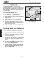
KX`cjkfZb
The tailstock (=`^li\(,) can be used to support
workpieces with a live or dead center. The lathe can drill
or bore holes in the center of a part with a drill bit held
by the tailstock. The tailstock can also be offset for cutting shallow tapers.
Quill Lock Lever
Offset
Scale
Kflj\k_\kX`cjkfZb#[fk_\j\jk\gj1
(%
Slide the tailstock to the desired position.
)%
Tighten the tailstock lock nut to lock the tailstock in
place on the ways.
*%
Loosen the quill lock lever to unlock the quill.
+%
Turn the quill feed handwheel clockwise to move
the quill towards the spindle or counterclockwise to
move away from the spindle.
,%
Tighten the quill lock lever to lock the quill in place.
FG<I8K@FEJ
;i`cc`e^N`k_k_\KX`cjkfZb
Kfj\klgk_\kX`cjkfZb]fi[i`cc`e^#[fk_\j\jk\gj1
(%
With the tailstock locknut tight, unlock the quill lock
lever.
)%
Turn the quill feed handwheel clockwise to extend
the quill about one inch.
*%
Insert the MT#3 arbor and chuck or an MT#3 tapered
drill shank into the quill until the taper is firmly
seated.
+%
Turn the quill feed handwheel clockwise to feed the
drill bit into the rotating workpiece.
,%
To remove the chuck and arbor, turn the quill feed
handle counterclockwise until the chuck is pushed
out of the tailstock taper.
-20-
Tailstock
Lock Nut
Offset
Adjustment
=`^li\(,% Tailstock and quill lock handles
in locked position.
Df[\cD('00D]^J`eZ\/&'.
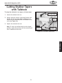
:lkk`e^J_XccfnKXg\ij
n`k_KX`cjkfZb
Kfj\klgk_\kX`cjkfZbkfZlkkXg\ij#[fk_\j\jk\gj1
Quill Lock Lever
(%
Loosen the tailstock lock nut.
)%
Using a 4mm hex wrench, alternately loosen and
tighten the left and right offset adjustment set
screws until the desired offset is indicated on the
scale (see =`^li\(-).
*%
Tighten the tailstock lock nut.
Efk\1 Kfi\kliek_\kX`cjkfZbYXZbkfk_\fi`^`eXc
gfj`k`fe#i\g\Xkk_\gifZ\jjlek`ck_\Z\ek\i\[gfj`$
k`fe`j`e[`ZXk\[fek_\jZXc\%
Offset
Scale
Tailstock
Lock Nut
Offset
Adjustment
=`^li\(-% Left offset adjustment.
FG<I8K@FEJ
-21-
Df[\cD('00D]^J`eZ\/&'.
8c`^e`e^KX`cjkfZb
The tailstock is factory aligned with the headstock. We
recommend that you take the time to ensure that the
tailstock is aligned to your own desired tolerances.
KfXc`^ek_\kX`cjkfZb#[fk_\j\jk\gj1
(%
Using a precision level on the bedways, make sure
the bedways are level side-to-side and front-to-back.
If the lathe is not level, correct this condition by
shimming the lathe base before proceeding.
)%
Get two pieces of steel round stock that are two
inches in diameter and six inches long.
*%
Center drill both ends of one piece of the round
stock. Set the round stock aside for use in Jk\g-%
+%
Using the other piece of stock, make a dead center by turning a shoulder to make a shank. Flip the
piece over in the chuck and turn a 60º point (see
=`^li\(.)%
FG<I8K@FEJ
Efk\1 8jcfe^Xjk_\[\X[Z\ek\ii\dX`ej`ek_\
Z_lZb#k_\gf`ekf]pfliZ\ek\in`cci\dX`ekil\kf
k_\jg`e[c\Xo`j%B\\g`ed`e[k_Xkk_\gf`ekn`cc
_Xm\kfY\i\]`e`j_\[n_\e\m\i`k`ji\dfm\[Xe[
i\klie\[kfk_\Z_lZb%
,%
Place the live center in the tailstock.
-%
Attach a lathe dog to the round stock and mount it
between centers%
.%
Turn approximately 0.010" off the diameter.
/%
Mount a dial indicator so the dial plunger is on the
tailstock barrel before moving the tailstock.
0%
Measure the stock diameter with a micrometer.
— If it is thicker at the tailstock end, move the
tailstock toward you half of the diameter (=`^li\j
(/20).
— If it is thinner at the tailstock end, move the
tailstock away from you half the distance of the
diameter (=`^li\(020).
('% Turn another 0.010" off of the diameter and check
for a taper. Repeat this process as necessary until
the desired amount of accuracy is achieved.
-22-
=`^li\(.% Chuck centering the dead
center.
=`^li\(/% Tailstock adjustment option #1.
=`^li\(0%Tailstock adjustment option #2.
Tailstock
Lock Nut
Offset
Scale
Left Offset
Set Screw
=`^li\20% Left offset adjustment.
Df[\cD('00D]^J`eZ\/&'.
:\ek\ij
A dead center can be used in the tailstock and lathe
spindle to support workpieces. When used in this manner, make sure to keep the dead center tip and workpiece
lubricated to prevent tip galling.
Kf`ejkXccX[\X[fic`m\Z\ek\i#[fk_\j\jk\gj1
(%
Feed the quill out about 1" and insert the dead center (=`^li\)(). The mating tapers provide the locking fit.
)%
Move the tailstock into position and lock in place.
=X`cli\kfb\\g[\X[Z\ek\igf`ekn\cc
clYi`ZXk\[n`cc^Xcck_\[\X[Z\ek\iXe[
nfibg`\Z\%
Efk\1DXb\jli\k_\i\`jXZ\ek\i[i`cc\[_fc\`ek_\
\e[f]k_\nfibg`\Z\]fik_\[\X[Z\ek\i%
*%
Feed the quill into the workpiece. +%
Lock the quill into place once the dead center and
the workpiece rotate together. The quill may need to
be adjusted during operation.
,%
To remove the dead center, retract the quill until
the dead center pops free.
=`^li\)(% Inserted dead center.
FG<I8K@FEJ
Kf`ejkXccXeDK+[\X[Z\ek\i`ek_\jg`e[c\#[fk_\j\
jk\gj1
(% DISCONNECT POWER TO THE LATHE!
)%
Remove the chuck from the spindle.
*%
Install the MT#4 dead center in the spindle.
+%
Attach the faceplate to the spindle, see =`^li\ )).
Refer to Dflek`e^:_lZbXe[=XZ\gcXk\ on GX^\(for details if required.
Efk\1 N_\elj`e^k_\[\X[Z\ek\i`ek_\jg`e[c\#
lj\XcXk_\[f^jfk_XkpfligXikn`ccifkXk\n`k_
k_\]XZ\gcXk\Xe[efkjg`efek_\[\X[Z\ek\ik`g%
-23-
=`^li\))% Faceplate and dead center
setup.
Df[\cD('00D]^J`eZ\/&'.
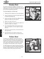
Jk\X[pI\jk
The steady rest serves as a support for long shafts. The
steady rest can should be placed along the ways where the
most support can be given to the workpiece and still allow
for all of your intended lathe operations.
Finger
Lock Nut
Adjustment
Knob
Finger
Kflj\k_\jk\X[pi\jk#[fk_\j\jk\gj1
FG<I8K@FEJ
(% Carefully place the steady rest on the lathe bedways.
)%
Loosen the finger lock nuts so the finger position can
be adjusted (see =`^li\)*).
*%
Loosen the steady rest lock nut (see =`^li\)*), and
position the steady rest where desired.
+%
Tighten the steady rest lock nut.
,%
Clamp the workpiece into the chuck and position the
tailstock to support the workpiece.
-%
Turn the adjustment knobs so the fingers are snug
against the workpiece, and then tighten the finger
lock nuts.
.%
Lubricate the finger tips with an anti-seize lubricant
during operation.
/%
After prolonged use, the fingers will show wear.
Either mill or file the tips for a new contact surface.
Steady
Rest
Lock Nut
=`^li\)*% Steady rest.
=fccfnI\jk
The follow rest in =`^li\)+ is mounted on the front
of the carriage directly above the ways and follows the
movement of the tool. The follow rest requires only two
fingers, as the cutting tool acts as the third. The follow
rest is used on long, slender parts to prevent flexing of
the workpiece from the pressure of the cutting tool.
Adjustment Knob
Finger
Lock Nut
Finger
The sliding fingers are set similar to those of the steady
rest—free of play but not binding. Always lubricate during
operation. After prolonged use, the fingers will need to
be milled or filed to clean up the contact surface.
Carriage
Cap
Screw
=`^li\)+% Follow rest.
-24-
Df[\cD('00D]^J`eZ\/&'.
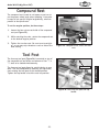
:fdgfle[I\jk
The compound rest is used to cut tapers on parts or to
set the proper infeed angle when threading. It may also
be used to cut specific lengths longitudinally, when set
parallel to the spindle axis.
Kfj\kk_\Xe^lcXigfj`k`fe#[fk_\j\jk\gj1
(%
Loosen the hex nuts on each side of the compound
rest (see =`^li\),).
)%
While watching the scale, rotate the compound rest
to the desired angular position.
*%
Tighten the two hex nuts. Be sure to not overtighten, as you may strip threads or crack or distort the
base casting.
Hex Nut
Scale
=`^li\),% Compound rest, scale, and hex
nuts.
KffcGfjk
The four-way tool post (=`^li\)-) is mounted on top of
the compound rest and allows a maximum of four 3⁄8" x
3
⁄8" tools to be loaded simultaneously.
Top Handle
=`^li\)-% Four-way tool post and top
handle.
-25-
FG<I8K@FEJ
The four-way tool post allows for quick indexing to new
tools. This is accomplished by loosening the top handle,
then rotating the tool post to the desired position.
Tighten the top handle to lock the tool into position.
Df[\cD('00D]^J`eZ\/&'.
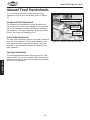
DXelXc=\\[?Xe[n_\\cj
You can manually move the cutting tool around the
workpiece using the three handwheels shown in =`^li\
)..
Compound Rest Handwheel
:fdgfle[I\jk?Xe[n_\\c
The compound rest handwheel controls the position of
the cutting tool relative to the workpiece. The graduated
dial on the handwheel indicates the depth of compound
rest movement. The angle adjustment is held by two hex
nuts on the base of the compound rest.
Cross Slide
Handwheel
Carriage
Handwheel
:ifjjJc`[\?Xe[n_\\c
The cross slide handwheel moves the top slide toward and
away from the workpiece. Turning the handwheel clockwise moves the slide toward the workpiece. The graduated dial on the handwheel indicates the depth of cross
slide movement.
FG<I8K@FEJ
:Xii`X^\?Xe[n_\\c
The carriage handwheel moves the carriage left or right
along the bed. This control is helpful when setting up the
machine for turning or when manual movement is desired
during turning operations.
-26-
=`^li\).% Manual handwheel controls.
Df[\cD('00D]^J`eZ\/&'.
;\k\id`e`e^:fii\Zk
Jg`e[c\IGD
Kf[\k\id`e\k_\Zfii\Zkjg`e[c\IGD#[fk_\j\jk\gj1
(%
Use the table in =`^li\)/to determine the cutting
speed required for the material of your workpiece.
)%
Measure the diameter of your workpiece in inches
and subtract the depth of the cut that will be taken
on the initial pass.
*%
Use the formula in =`^li\)0 to determine the
needed RPM for your operation.
Efk\1 8cnXpjifle[kfk_\Zcfj\jkIGD^`m\efek_\
jg`e[c\jg\\[Z_Xik#Xe[X[aljkpflijg\\[Xjk_\
nfibg`\Z\[`Xd\k\i[\Zi\Xj\j%
<oXdgc\(
You have a piece of 1⁄2" diameter aluminum stock,
and you are using workpiece with a HSS cutting tool.
Jk\g)1
1200 / 0.5" (Diameter of workpiece) = 2400 RPM
I\jlck1
The needed speed for this workpiece is 2400 RPM.
<oXdgc\)
You have a piece of 1" diameter stainless steel stock,
and you are using a workpiece with a carbide cutting
tool.
Jk\g(1
60 (SFM from chart) x 2 (for carbide tool) = 120
Jk\g)1
120 (determined SFM) x 4 = 480
:lkk`e^Jg\\[j]fi?`^_Jg\\[Jk\\c
?JJ :lkk`e^Kffcj
Workpiece Material
Aluminum & alloys
300
Brass & Bronze
150
Copper
100
Cast Iron, soft
80
Cast Iron, hard
50
Mild Steel
90
Cast Steel
80
Alloy Steel, hard
40
Tool Steel
50
Stainless Steel
60
Titanium
50
Plastics
300-800
Wood
300-500
Efk\1 =fiZXiY`[\Zlkk`e^kffcj#[flYc\
k_\Zlkk`e^jg\\[%K_\j\mXcl\jXi\X
^l`[\c`e\fecp% Refer to the D8:?@E$
<IPJ?8E;9FFB for more detailed
information.
=`^li\)/% Cutting speed table for HSS
cutting tools.
J=D o+
Nfibg`\Z\
;`Xd\k\i
Jk\g*1
480 / 1" (Diameter of workpiece) = 480 RPM
I\jlck1
The needed speed for this workpiece is 480 RPM.
-27-
Cutting Speed
(sfm)
4IGD
=`^li\)0% Formula to determine required
spindle speed for lathes.
FG<I8K@FEJ
Jk\g(1
300 (SFM from chart) x 4 = 1200
=X`cli\ kf ]fccfn IGD Xe[ ]\\[ iXk\
^l`[\c`e\jdXpk_i\Xk\efg\iXkfijX]\$
kp]ifd\a\Zk\[gXikjfiYifb\ekffcj%
Df[\cD('00D]^J`eZ\/&'.
Jg`e[c\IGD
This lathe has six possible spindle speeds. Shown in
=`^li\*' is an example of how you would use the chart
to get a spindle RPM of 150.
Lj\ X cfn IGD n_\e
dXZ_`e`e^ _\Xmp \ZZ\eki`Z
nfibg`\Z\j2 FYa\Zkj k_ifne
]ifd X cXk_\ ZXe ZXlj\ j\i`$
flj`ealipfi[\Xk_%
Kfj\kk_\jg`e[c\IGD#[fk_\j\jk\gj1
(%
DISCONNECT THE LATHE FROM POWER!
)%
Refer to the RPM chart in =`^li\*' and determine
which pulley combination you will need to get a particular spindle RPM.
*%
Open the side cover and install the low range belt
between pulleys 9 and : and in sheave ( as shown in
=`^li\*'.
Lj\ X d`e`dld f] k_i\\ `e[\g\e$
[\ek ZcXdg`e^ [\m`Z\j n_\e klie`e^
\ZZ\eki`Znfibg`\Z\jfek_\]XZ\gcXk\%
=X`cli\ kf gifm`[\ X[\hlXk\ ZcXdg`e^
n`ccZXlj\nfibg`\Z\kf\a\Zk%
Efk\1 K_\cfniXe^\Y\ck`jXcnXpjlj\[feglcc\pj
9Xe[:n`k_k_\k\ej`fe\i%K_`jY\ck`j).%,cfe^%
K_\_`^_iXe^\Y\ck`jXcnXpjlj\[feglcc\pj8Xe[
:n`k_flklj`e^k_\k\ej`fe\i%K_`jY\ck`j**cfe^%
FG<I8K@FEJ
+% Close the side cover and secure it shut with the cap
screw. The lathe is now ready to use at 150 RPM.
RPM Chart
:
9
4(,'IGD
Tensioner
8
=`^li\*'% Pulley combination (BC1) achieves 150 RPM at the spindle.
-28-
Df[\cD('00D]^J`eZ\/&'.
Gfn\i=\\[IXk\
Use these steps to learn how to setup your lathe for a
power feed operation. The example in =`^li\*) shows
lathe setup for a power feed rate of 0.012". Remember,
the carriage direction is reversed when spindle rotation is
reversed.
Kfj\kXe[\e^X^\k_\gfn\i]\\[#[fk_\j\jk\gj1
(%
DISCONNECT LATHE FROM POWER!
)%
Turn the feed dials to the numeral and letter indicated by the chart in=`^li\*).
*%
Using the chart in=`^li\*), gather the required
change gears.
+%
Open the side cover and use a 6mm hex wrench to
loosen the lash adjuster (=`^li\*)) and swing the
change gear assembly out of the way.
,%
Remove the spindle E-clips and cap screw, lubricate,
and swap out the change gears in the order shown
on the chart in =`^li\*)%
Move the lash adjuster so the gear backlash is
between 0.003" to 0.008", tighten the lash adjuster
cap screw, and close the side cover.
.%
Using a 5mm hex wrench, loosen the carriage lock
(=`^li\*(), and use the half nut lever to engage
and disengage the power feed when required.
Carriage Lock
Cap Screw
Half Nut
Lever
=`^li\*(% Carriage lock and feed control.
FG<I8K@FEJ
-%
=\\[iXk\`jYXj\[fejg`e[c\IGD%GXp
Zcfj\ Xkk\ek`fe kf k_\ ]\\[ iXk\ pfl
_Xm\Z_fj\eXe[Y\i\X[pkf[`j\e^X^\
k_\ ZXii`X^\% =X`cli\ kf [f k_`j dXp
ZXlj\ k_\ ZXii`X^\ kf ZiXj_ `ekf k_\
Z_lZb%
+'
Feed Chart
-'
).
,-
Change Gears
().
('+
4'%'()=\\[
Lash Adjuster
=`^li\*)% Power feed setup.
-29-
Feed Dials
Df[\cD('00D]^J`eZ\/&'.
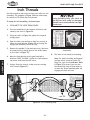
@eZ_K_i\X[j
Use these steps to learn how to setup your lathe for inch
threading. The example in =`^li\*+ shows lathe setup
for cutting 64 TPI (Teeth Per/Inch) thread.
;li`e^ k_i\X[`e^ b\\g pfli _Xe[ fe
k_\ _Xc]$elk c\m\i i\X[p kf [`j\e^X^\
k_\_Xc]elkkfXmf`[gfk\ek`XcZXii`X^\&
Z_lZbZiXj_%
Kfj\klg]fi`eZ_k_i\X[`e^#[fk_\j\jk\gj1
(%
DISCONNECT THE LATHE FROM POWER!
)%
Turn the feed dials to the numeral and letter indicated by the chart in=`^li\*+.
*%
Using the chart in=`^li\*+, gather the required
change gears.
+%
Open the side cover and use a 6mm hex wrench to
loosen the lash adjuster (=`^li\*)) and swing the
change gear assembly out of the way.
,%
Remove the spindle E-clips and cap screw, lubricate,
and swap out the change gears in the order shown
on the chart in =`^li\*)%
FG<I8K@FEJ
-%
.%
Move the lash adjuster so the gear backlash is
between 0.003" to 0.008", tighten the lash adjuster
cap screw, and close the side cover.
Using a 5mm hex wrench, make sure the carriage
lock is loose (=`^li\*().
=`^li\**% Thread dial chart and
thread dial.
/%
The lathe is now setup for threading.
Efk\1 =fi]Xjk\ik_i\X[`e^Xe[dXelXc
ZXii`X^\i\klie#YXj\[fen_`Z_KG@
Y\`e^Zlk#i\]\ikfk_\@e[`ZXkfiKXYc\
`e =`^li\**kfbefn`]pflZXelj\
k_\k_i\X[[`XcjZXc\kfj_fnn_\ekf
i\$\ek\ik_\k_i\X[dXelXccpX]k\i[`j$
\e^X^`e^k_\_Xc]elkc\m\i%
Inch
Thread
Chart
X
4-+KG@
Y
=`^li\*+% Inch threading setup.
-30-
Df[\cD('00D]^J`eZ\/&'.
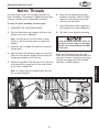
D\ki`ZK_i\X[j
Use these steps to learn how to setup your lathe for
metric threading. The example in =`^li\*, shows lathe
setup for cutting a metric thread pitch of 0.45mm.
-%
Move the lash adjuster so the gear
backlash is between 0.003" to 0.008",
tighten the lash adjuster cap screw,
and close the side cover.
.%
Using a 5mm hex wrench, make sure
the carriage lock is loose (=`^li\*().
/%
The lathe is now setup for threading.
Kfj\klg]fid\ki`Zk_i\X[`e^#[fk_\j\jk\gj1
(%
DISCONNECT THE LATHE FROM POWER!
)%
Turn the feed dials to the numeral and letter indicated by the chart in=`^li\*,.
Efk\1 PfldXp_Xm\kfifZbk_\Z_lZbYp_Xe[
jc`^_kcpkf^\kk_\^\XiYfo^\Xijkf\e^X^\fe\
Xefk_\i%
Using the chart in=`^li\*+, gather the required
change gears.
+%
Open the side cover and use a 6mm hex wrench to
loosen the lash adjuster (=`^li\*)) and swing the
change gear assembly out of the way.
,%
Remove the spindle E-clips and cap screw, lubricate,
and swap out the change gears in the order shown
on the chart in =`^li\*)%
Efk\1 8ccZ_Xe^\^\XijXi\jkXdg\[n`k_k_\eld$
Y\if]k\\k_k_\p_Xm\%
Efk\1 J`eZ\k_`jcXk_\_XjXe`eZ_c\X[
jZi\n#[fefklj\k_\k_i\X[[`Xcn_\eZlk$
k`e^d\ki`Zk_i\X[j%@ejk\X[pfldljkc\Xm\
k_\_Xc]elk\e^X^\[lek`ck_\k_i\X[`e^
fg\iXk`fe`jkfkXccpZfdgc\k\%
Metric Thread Chart
X
4'%+,dd
Y
=`^li\*,% Metric threading setup.
-31-
FG<I8K@FEJ
*%
;li`e^ k_i\X[`e^ b\\g pfli _Xe[ fe
k_\ _Xc]$elk c\m\i i\X[p kf [`j\e^X^\
k_\_Xc]elkkfXmf`[gfk\ek`XcZXii`X^\&
Z_lZbZiXj_%
Df[\cD('00D]^J`eZ\/&'.
D8@EK<E8E:<
9Xj`ZDX`ek\eXeZ\
Regular periodic maintenance of your lathe will ensure
optimum performance. Make a habit of inspecting your
machine each time you use it.
Gearbox Oil Fill
:_\Zb]fik_\]fccfn`e^Zfe[`k`fejXe[i\gX`ifi
i\gcXZ\n_\ee\Z\jjXip1
Loose mounting bolts and chuck.
Worn switch or safety features.
Worn or damaged cords or plug.
Any other condition that could hamper the safe
operation of this machine.
>\e\iXcClYi`ZXk`fe
Gearbox
Oil Level
Sight Glass
=`^li\*-% Headstock oil level sight glass.
Spindle Oil Balls
Make sure to unplug the lathe before lubrication and
cleaning.
D8@EK<E8E:<
Keep the gearbox oil level at 3⁄4 full as shown by the sight
glass (=`^li\*-). After break-in, change the oil in the
gearbox with Mobil® DTE® Heavy-Medium or an equivalent
grade of oil, then again after three months. After that,
change the oil at the same time on an annual basis or
more frequently if extreme machine use requires it.
For daily lubrication, use a manual oil gun with a general
10W machine oil to lubricate the 11 ball oilers. Refer to
=`^li\j*.-+'for ball oiler locations. Make sure you wipe
off the fittings before you oil them.
Headstock
=`^li\*.% Spindle ball oilers in headstock.
To control surface rust on machined surfaces, wipe the
unprotected metal as required with a rust inhibiting oil.
Never blow the lathe off with compressed air, otherwise
you will force metal shavings deep into mechanisms. Use
a shop vacuum instead. Never use acetone, gasoline, or
lacquer thinner to remove stains or oil from painted surfaces. These chemicals will melt the paint. Use mineral
spirits or mild household degreasers.
Ball
Oiler
Gearbox
Drain
=`^li\*/% Change gear ball oilers and
gearbox drain.
-32-
Df[\cD('00D]^J`eZ\/&'.
=`^li\*0%Apron and carriage ball oilers.
=`^li\+'%Leadscrew and tailstock ball oilers.
D8@EK<E8E:<
-33-
Df[\cD('00D]^J`eZ\/&'.
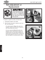
9\ck8[aljkd\ekfi
I\gcXZ\d\ek
<EK8E>C<D<EK?8Q8I;
;`jZfee\Zkk_`jcXk_\]ifdgfn\i
Xe[nX`klek`cXccjg`ee`e^gXikj
_Xm\ Zfd\ kf X Zfdgc\k\ jkfg
Y\]fi\ pfl XZZ\jj k_\ Y\ck Xe[
glcc\pj% Fk_\in`j\ pfl dXp Y\
j\m\i\cp`eali\[
:
8
Kfi\gcXZ\fiX[aljkk_\M$Y\ckj#[fk_\j\jk\gj1
(%
DISCONNECT POWER TO THE LATHE!
)%
Open the side access door to expose the belt, pulleys, and change gears.
=`^li\+(% High-range belt position (A-C).
— If the high range belt (=`^li\+() needs to be
replaced, carefully roll the belt off of pulleys 8
and : and reinstall the new one.
— If the low range belt (=`^li\+)) needs to be
replaced, use the 17mm wrench to loosen the
tensioner pulley arm that holds the pulley and
replace the belt on pulleys 9 and :% Hold the tensioner pulley against the new belt so the belt is
tight, and tighten the tensioner pulley in place.
:
9
Tensioner Pulley
J<IM@:<
=`^li\+)% Low-range belt position (B-C).
-34-
Df[\cD('00D]^J`eZ\/&'.
J<IM@:<
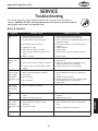
KiflYc\j_ffk`e^
This section covers the most common problems and corrections with this type of
machine. N8IE@E>;FEFKdXb\XepX[aljkd\ekjlek`cgfn\i`j[`jZfee\Zk\[Xe[
dfm`e^gXikj_Xm\Zfd\kfXZfdgc\k\jkfg
Dfkfi>\XiYfo
JPDGKFD
Motor will not
start.
GFJJ@9C<:8LJ<
:FII<:K@M<8:K@FE
1. Main power panel switch is F==.
2. Emergency switch is pushed in.
3. Circuit breaker or fuse has tripped.
4. No voltage or open connection.
5. Capacitor is at fault.
6. Motor direction switch is at fault.
7. Power switch or magnetic contactor is at
fault.
8. Motor is at fault.
Fuses or circuit
breakers trip
open.
1. Short circuit in line cord or plug.
2. Short circuit in motor or loose connections.
3. Incorrect fuses or circuit breakers in power
supply.
Excessive depth of cut.
RPM or feed rate wrong for operation.
Dull cutters.
Belt is slipping.
1. Turn the main power panel switch FE.
2. Rotate emergency switch so it pops out.
3. Seek an electrician to troubleshoot and repair the
shop power supply.
4. Test circuit, replace wires and connections as
required.
5. Replace capacitor.
6. Replace switch.
7. Replace power switch or magnetic contactor.
8. Replace motor.
1. Inspect cord or plug for damaged insulation and
shorted wires.
2. Inspect all connections on motor for loose or
shorted terminals or worn insulation.
3. Install correct fuses or circuit breakers.
1. Decrease depth of cut.
2. Refer to RPM feed rate chart for appropriate
rates.
3. Sharpen or replace cutters.
4. Remove grease or oil on belt or pulleys/tighten
belt tensioner against low range belt.
5. Replace belt.
Machine is
loud, belt slips
when cutting.
Overheats or
bogs down in the
cut.
1.
2.
3.
4.
Gear change
levers will not
shift into position.
1. Gears not aligned in headstock.
1. Rotate spindle by hand until gear falls into place.
Loud, repetitious
noise.
1. Pulley set screws or keys are missing or
loose.
2. Motor fan is hitting the cover.
1. Inspect keys and set screws. Replace or tighten if
necessary.
2. Replace fan and cover.
5. Belt is at fault.
1. Decrease depth of cut or feed rate.
2. Refer to RPM feed rate chart for appropriate
rates.
Levers will not
shift.
1. Rotate spindle by hand until gear falls into place.
3. Sharpen or replace the cutting tool.
1. Gears not aligned in headstock.
-35-
J<IM@:<
1. Excessive depth of cut or feed rate.
Motor is loud
2. RPM or feed rate wrong for cutting
when cutting.
operation.
Overheats or
bogs down in the 3. Cutting tool is dull.
cut.
Df[\cD('00D]^J`eZ\/&'.
KiflYc\j_ffk`e^
Fg\iXk`feXe[NfibI\jlckj
JPDGKFD
GFJJ@9C<:8LJ<
:FII<:K@M<8:K@FE
Lathe vibrates
excessively.
1. Workpiece is unbalanced.
2. Worn or broken gear present.
3. Chuck or faceplate has become unbalanced.
4. Spindle bearings at fault.
1. Reinstall workpiece so it is centered.
2. Inspect gears and replace if necessary.
3. Rebalance chuck or faceplate; contact a local
machine shop for help.
4. Tighten or replace spindle bearings.
Cutting tool
vibrates excessively during cutting.
1. Tool holder not tight enough.
2. Cutting tool sticks too far out of tool holder;
lack of support.
3. Gibs are out of adjustment.
4. Dull cutting tool.
5. Incorrect spindle speed or feed rate.
1. Check for debris, clean, and retighten.
2. Reinstall cutting tool so no more than 1/3 of the
total length is sticking out of tool holder.
3. Tighten gib screws at affected component.
4. Replace or re-sharpen cutting tool.
5. Use the recommended spindle speed.
Can't remove
tool from
tailstock.
1. Quill had not retracted all the way back into
the tailstock.
1. Turn the quill handwheel until it forces taper out
of quill.
Cross slide, com- 1. Gibs are out of adjustment.
pound rest, or
2. Handwheel is loose.
carriage feed has 3. Lead screw mechanism worn or out of
lash.
adjustment.
1. Tighten gib screw(s).
2. Tighten handwheel fasteners.
3. Tighten any loose fasteners on lead screw mechanism.
Cross slide, compound rest, or
carriage feed
handwheel is
hard to move.
1. Gibs are loaded up with shavings or grime.
1. Remove gibs, clean ways/dovetails, lubricate, and
readjust gibs.
2. Loosen gib screw(s) slightly, and lubricate
bedways.
3. Slightly loosen backlash setting by loosening the
locking screw and adjusting the spanner ring at
the end of the handle.
4. Lubricate bedways and handles.
Bad surface finish.
1. Wrong RPM or feed rate.
2. Dull tooling or poor tool selection.
2. Gib screws are too tight.
3. Backlash setting too tight (cross slide only).
J<IM@:<
4. Bedways are dry.
3. Too much play in gibs.
4. Tool too high.
1. Adjust RPM and feed rate.
2. Sharpen tooling or select a better tool for the
intended operation.
3. Tighten gibs.
4. Lower the tool position.
Inaccurate turning results from
one end of the
workpiece to the
other.
1. Headstock and tailstock are not properly
aligned with each other.
1. Realign the tailstock to the headstock spindle bore
center line.
Carriage won't
feed, or is hard
to move.
1.
2.
3.
4.
1.
2.
3.
4.
Gears are not all engaged or broken.
Gibs are too tight.
Loose screw on the feed handle.
Lead screw shear pin has sheared.
-36-
Adjust gear positions or replace.
Loosen gib screw(s) slightly.
Tighten.
Correct for cause of shear pin breakage, and
replace shear pin.
Df[\cD('00D]^J`eZ\/&'.
:ifjjJc`[\9XZbcXj_
8[aljkd\ek
Backlash is the amount of play found in a lead screw. It
can be found by turning the cross slide handwheel in one
direction, then turning the handwheel the other direction.
When the cross slide begins to move, the backlash has
been taken up.
1 of 3 Cross Slide Gib
Adjustment Points
Cross Slide
Backlash
Adjustment
Cap Screw
Efk\18mf`[k_\k\dgkXk`fekffm\ik`^_k\ek_\Zifjjjc`[\
YXZbcXj_jZi\n%Fm\ik`^_k\e`e^n`ccZXlj\\oZ\jj`m\n\Xi
kfk_\jc`[`e^YcfZbXe[c\X[jZi\n%
Backlash is adjusted by tightening or loosening the screw
shown in =`^li\+*.
=`^li\+*%Cross slide adjustment.
This screw draws a wedge-type nut against the lead screw
and main nut. If it is too tight, loosen the screw a few
turns and tap the cross slide a few times with a rubber or wooden mallet. Then turn the handle slowly back
and forth until the handle turns freely. To readjust the
backlash, rock the handle back and forth and tighten the
screw slowly until the backlash is at between 0.001" to
0.002" as indicated on the handwheel.
Efk\1I\[lZ`e^YXZbcXj_kfc\jjk_Xe'%''(`j`dgiXZk`ZXc
Xe[i\[lZ\jk_\c`]\f]k_\Zifjjjc`[\%
>`Y8[aljkd\ekj
3 Compound Rest Gib
Adjustment Points
=`^li\++%Gib adjustment points.
When adjusting gibs (=`^li\j++Xe[+,), the goal is to
remove sloppiness in the ways without causing the slides
or half nut to bind. Loose gibs will cause a poor finish on
the workpiece and wear the slide. Tight gibs will damage
the slide, lead screw, and half-nut. The cross slide gib is a
tapered piece of iron. When the opposing front and rear
gib adjustment screws are turned in opposing directions,
the screws force the tapered gibs to fill the void in the
way, thus tightening the play in the cross slide. If more
play is needed turn the screws the other direction.
3 Saddle Gib
Adjustment Points
=`^li\+,%Half-nut saddle gib locations.
-37-
J<IM@:<
For the three saddle gibs (=`^li\++), loosen the jam
nuts and turn the three set screws until slight tension is
felt and the gib plates are slightly pre-loaded against the
underside of the flat-way. Tighten the jam nuts when finished.
Half Nut Gib
Adjustments
Points
(Thread Dial
Removed)
Df[\cD('00D]^J`eZ\/&'.
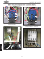
<c\Zki`ZXc:fdgfe\ek:fee\Zk`fej
=`^li\+-% Motor rotary switch and ON power
switch (SA and SB1).
J<IM@:<
=`^li\+/% Motor rotary switch and
emergency stop switch (SA and SB2).
=`^li\+0% Motor start contactor.
=`^li\+.% External motor capacitors.
-38-
Df[\cD('00D]^J`eZ\/&'.
=`^li\,(% Motor connection detail.
=`^li\,'% Motor data plate.
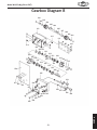
N`i`e^;`X^iXd
J<IM@:<
C<><E;
:(1:XgXZ`kfi
:)1:XgXZ`kfi
J81Dfkfi;`i\Zk`feIfkXipJn`kZ_
BD1DX^e\k`Z:fekXZkfi(('M
J9(1FEGlj_9lkkfeJn`kZ_
J9)1<d\i^\eZpJkfgGlj_9lkkfeJn`kZ_
D1Dfkfi(('M
-39-
Df[\cD('00D]^J`eZ\/&'.
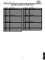
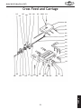
G8IKJ
Jg`e[c\Xe[;i`m\9\ck
1
2
5
6
7
8
10
11
12
13
14
15
27
28
16
26
17
29
30
22
19
25
20
21
23 24
32
31
33
42
34
43
35
40
41
49
36
37
38
39
44
45
46
G8IKJ
51
52
47
53
-40-
48
18
Df[\cD('00D]^J`eZ\/&'.
Jg`e[c\Xe[;i`m\9\ckGXikj
REF
1
2
5
6
7
8
10
11
12
13
14
15
16
17
18
19
20
21
22
23
24
25
26
27
28
PART#
XM1099001
XPS17M
XPSB06M
XPW03M
XM1099007
XM1099008
XPSB06M
XM1099011
XPK123M
XM1099013
XM1099014
XM1099015
XPSB14M
XM1099014
XPSB02M
XM1099019
XM1099020
XPVM27A
XM1099022
XPVM33
XM1099024
XM1099025
XPLW06M
XPN02M
XPW04M
DESCRIPTION
CONTROLPANELFACE
PHLPHDSCRM4-.7X6
CAPSCREWM6-1X25
FLATWASHER6MM
COMPRESSIONSPRING
CLAMP
CAPSCREWM6-1X25
SPINDLE
KEY10X10X55
SPACER
BALLBEARING(45X75X20)
HEADSTOCK
CAPSCREWM8-1.25X20
BALLBEARING(45X75X20)
CAPSCREWM6-1X20
SPACER
GEAR
V-BELTM-27.53L275
PULLEY
V-BELTM-333L330
SPANNERNUTM30X1.5
BRACKETPLATE
LOCKWASHER10MM
HEXNUTM10-1.5
FLATWASHER10MM
REF
29
30
31
32
33
34
35
36
37
38
39
40
41
42
43
44
45
46
47
48
49
51
52
53
PART#
XPSB50M
XPW02M
XM1099031
XM1099032
XP6001
XM1099034
XPR03M
XM1099036
XM1099037
XPK11M
XM1099039
XM1099040
XM1099041
XPW04M
XPN02M
XM1099044
XM1099045
XM1099046
XPR20M
XPR03M
XM1099049
XPN06M
XM1099052
XPS08M
DESCRIPTION
CAPSCREWM5-.8X10
FLATWASHER5MM
SPINDLESHAFT
COGGEDBELT263L
BALLBEARING6001
COGGEDPULLEY
EXTRETAININGRING12MM
SPACER
COGGEDPULLEY
KEY6X6X40
SPACER
STUD
PLATE
FLATWASHER10MM
HEXNUTM10-1.5
SPINDLESHAFT
BALLBEARING(12X28X8)
ROLLER
INTRETAININGRING28MM
EXTRETAININGRING12MM
COVER
HEXNUTM5-.8
COVER
PHLPHDSCRM5-.8X12
G8IKJ
-41-
Df[\cD('00D]^J`eZ\/&'.
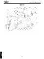
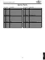
8gife
113
111
112
110
114
109
108
107
106
105
104
115
116
103
117
118
119
102
120
121
122
123
124
101
125
126
127
128
129
132
131
134
136
140
138
142
135 137
141
139
G8IKJ
130
133
-42-
Df[\cD('00D]^J`eZ\/&'.
8gifeGXikj
REF
101
102
103
104
105
106
107
108
109
110
111
112
113
114
115
116
117
118
119
120
121
PART#
XPRP19M
XM1099102
XPRP59M
XM1099104
XM1099105
XPRP73M
XM1099107
XPSB23M
XM1099109
XPRP76M
XPSS34M
XPSS12M
XPN06M
XPSS04M
XM1099115
XM1099116
XM1099117
XM1099118
XPSB85M
XM1099120
XM1099121
DESCRIPTION
ROLLPIN4X14
HALFNUT
ROLLPIN5X12
GEARSHAFT
GEAR
ROLLPIN4X30
APRONCASTING
CAPSCREWM4-.7X12
GIB
ROLLPIN4X16
SETSCREWM5-.8X16
SETSCREWM6-1X25
HEXNUTM5-.8
SETSCREWM6-1X12
LEVERHUB
LEVER
LEVERHANDLE
STEELBALL
CAPSCREWM6-1X6
DIAL
RIVET2X5
REF
122
123
124
125
126
127
128
129
130
131
132
133
134
135
136
137
138
139
140
141
142
PART#
XM1099122
XM1099123
XPK39M
XPSB83M
XM1099126
XM1099127
XPW01M
XPN03M
XPSS02M
XM1099131
XM1099132
XM1099133
XPRP04M
XM1099135
XM1099136
XPFH43M
XPW03M
XM1099139
XM1099140
XM1099141
XM1099142
DESCRIPTION
POINTER
SHAFT
KEY3X3X10
CAPSCREWM6-1X55
THREADDIALBODY
SIDEGEAR
FLATWASHER8MM
HEXNUTM8-1.25
SETSCREWM6-1X6
COMPRESSIONSPRING
HANDLE
HANDWHEEL
ROLLPIN4X24
POINTEDSETSCRM6-1X12
GEARSHAFT
FLATHDSCRM6-1X10
FLATWASHER6MM
INDICATORPLATE
SHAFT
THREADEDDIALPLATE
LOCKINGCAM
G8IKJ
-43-
Df[\cD('00D]^J`eZ\/&'.
Kffc?fc[\iXe[:fdgfle[I\jk
218
219
222
212
221
207
211
220
201
210
215
216
208
208
203
202
206
217A
217A-1
209
228
224
204
229
226
227
205
214
213
G8IKJ
223
225 230
231
REF
PART#
DESCRIPTION
REF
PART#
DESCRIPTION
201
202
203
204
205
206
207
208
209
210
211
212
213
214
215
216
XM1099201
XM1099202
XM1099203
XM1099204
XM1099205
XM1099206
XM1099207
XM1099208
XPW01M
XM1099210
XM1099211
XM1099212
XPSB31M
XPSB26M
XPSS34M
XPN06M
COMPOUNDREST
SWIVELBASE
GIB
CLAMPINGRING
GRADUATEDDIAL
BARRELNUT
DOWELPIN
TOOLPOSTSTUD
FLATWASHER8MM
DOWELPIN
COMPRESSIONSPRING
BULLNOSECAPSCRM8-1.25X30
CAPSCREWM8-1.25X25
CAPSCREWM6-1X12
SETSCREWM5-.8X16
HEXNUTM5-.8
217A
217A-1
218
219
220
221
222
223
224
225
226
227
228
229
230
231
XPSS19M
XPN03M
XM1099218
XM1099219
XM1099220
XM1099221
XM1099222
XM1099223
XM1099224
XM1099225
XM1099226
XM1099227
XPK03M
XM1099229
XM1099230
XPSS17M
SETSCREWM8-1.25X30
HEXNUTM8-1.25
HANDLE
HANDLEHUB
TOOLREST
RUBSPACER
SLIDEPLATE
LEADSCREW
LEADSCREWMOUNT
GRADUATEDDIAL
HANDWHEEL
HANDLE
KEY3X3X8
POINTER
THREADEDCOLLAR
SETSCREWM8-1.25X6
-44-
Df[\cD('00D]^J`eZ\/&'.
KX`cjkfZb
306
307
308
320
319
304
317
301
302
316
303
309
312
310
305
322
311
318
313
325
324
315
314
321
314
319
323
326
REF
301
302
303
304
305
306
307
308
309
310
311
312
313
PART#
XM1099301
XM1099302
XM1099303
XM1099304
XM1099305
XM1099306
XM1099307
XPSS04M
XM1099309
XM1099310
XM1099311
XM1099312
XM1099313
DESCRIPTION
TAILSTOCKQUILL
LEADSCREW
BUSHING
HANDWHEELSCALEPLATE
HANDWHEEL
LEVERBOLTM12-1.75X50
BARRELNUT
SETSCREWM6-1X12
GRADUATEDDIAL
POINTER
SPACER
TAILSTOCKBODY
TAILSTOCKBASE
REF
314
315
316
317
318
319
320
321
322
323
324
325
326
PART#
XPSS21M
XM1099315
XM1099316
XM1099317
XPLN05M
XM1099319
XM1099320
XM1099321
XPN09M
XPB158M
XPW06M
XPSS26M
XM1099326
DESCRIPTION
SETSCREWM8-1.25X25
HANDLE
OFFSETSCALEPLATE
LEADSCREWKEY
LOCKNUTM10-1.5
RIVET2X5
BALLOILER
CLAMPINGPLATE
HEXNUTM12-1.75
HEXBOLTM12-1.75X90
FLATWASHER12MM
SETSCREWM5-.8X6
PLATE
G8IKJ
-45-
Df[\cD('00D]^J`eZ\/&'.
9\[Xe[C\X[jZ\n
413
414
409
412
411
410
401
402
403
415
404 407 406
PART#
XM1099401
XM1099402
XPSB33M
XM1099404
XM1099405
XM1099406
XPSB02M
XPLN05M
DESCRIPTION
BED
RACK
CAPSCREWM5-.8X12
LEADSCREW
BRACKET
BALLOILER
CAPSCREWM6-1X20
LOCKNUTM10-1.5
REF
409
410
411
412
413
414
415
G8IKJ
REF
401
402
403
404
405
406
407
408
-46-
405
PART#
XM1099409
XM1099410
XPN02M
XPSS44M
XPW01M
XPN03M
XM1099415
408
DESCRIPTION
SPLASHGUARD
STUDM10-1.5X35
HEXNUTM10-1.5
SETSCREWM8-1.25X40
FLATWASHER8MM
HEXNUTM8-1.25
CHIPPAN
Df[\cD('00D]^J`eZ\/&'.
Jk\X[pI\jkXe[=fccfnI\jk
506
503
504
505
501
502
510
509
514
507 508
512
513
516
511
515
517
518
REF PART#
DESCRIPTION
REF PART#
DESCRIPTION
501
502
503
504
505
506
507
508
509
STEADYRESTCASTING
FINGER
T-BOLTM6-1
LOCKWASHER6MM
HEXNUTM6-1
ADJUSTINGSCREW
CLAMPINGPLATE
HEXBOLTM12-1.75X65
FLATWASHER10MM
510
511
512
513
514
515
516
517
518
HEXNUTM10-1.5
FOLLOWRESTCASTING
FINGER
T-BOLTM6-1
ADJUSTINGSCREW
HEXNUTM6-1
LOCKWASHER6MM
CAPSCREWM8-1.25X35
FLATWASHER8MM
XM1099501
XM1099502
XM1099503
XPLW03M
XPN01M
XM1099506
XM1099507
XPB125M
XPW04M
XPN02M
XM1099511
XM1099512
XM1099503
XM1099514
XPN01M
XPLW03M
XPSB40M
XPW01M
G8IKJ
-47-
Df[\cD('00D]^J`eZ\/&'.
DfkfiXe[<c\Zki`ZXc
611-5
611-3
604
610
611-4
612
611
602
611-6
603
601
617
611-1
607
608
611-2
615
616
DESCRIPTION
CABINET
CAPSCREWM6-1X25
LOCKWASHER6MM
COVER
STRAINRELIEFNUT
STRAINRELIEF
PHLPHDSCRM5-.8X10
REVERSIBLEMOTOR110V
FAN
REF
611-2
611-3
611-4
611-5
611-6
612
615
616
617
G8IKJ
REF PART#
601 XM1099601
602 XPSB06M
603 XPLW03M
604 XM1099604
607 XM1099607
608 XM1099608
610 XPS09M
611 XM1099611
611-1 XM1099611-1
-48-
PART#
XM1099611-2
XM1099611-3
XM1099611-4
XM1099611-5
XM1099611-6
XPLW03M
XM1099615
XM1099616
XM1099617
DESCRIPTION
FANCOVER
STARTCAPACITOR150MFD/125VAC
RUNCAPACITOR20MFD/400VAC
CAPACITORCOVERW/CAP
POWERCORD
LOCKWASHER6MM
STRAINRELIEF
STRAINRELIEFNUT
CONTACTOR3TB4122E110V
Df[\cD('00D]^J`eZ\/&'.
>\XiYfo;`X^iXd8
701
708
707
706
704
703 702
719
718 714
717
716
735
736
737
739
740
741
728
729
730
731
732
733
734
725
724
723
722
715
712
713
721
711
720
726
727
G8IKJ
-49-
Df[\cD('00D]^J`eZ\/&'.
>\XiYfo;`X^iXd8GXikj
REF PART #
DESCRIPTION
REF PART #
DESCRIPTION
701
702
703
704
706
707
708
711
712
713
714
715
716
717
718
719
720
721
722
SET SCREW M6-1 X 10
BUSHING
PLASTIC DRIVE GEAR (60-TOOTH)
CAST-IRON GEAR 27T
SHAFT
KNURELD KEEPER
BALL OILER
BRACKET
T-NUT
SPACER WASHER
SHAFT
BUSHING
GEAR 127T
GEAR 56T
KNURELD KEEPER
BALL OILER
BUSHING
KEY 4 X 4 X 14
SPACING RING
723
724
725
726
727
728
729
730
731
732
733
734
735
736
737
739
740
741
GEAR 104T
FLAT WASHER 6MM
CAP SCREW M6-1 X 6
LOCK WASHER 8MM
CAP SCREW M8-1.25 X 40
CHANGE GEAR (36-TOOTH)
CHANGE GEAR (36-TOOTH)
CHANGE GEAR (40-TOOTH)
CHANGE GEAR (44-TOOTH)
CHANGE GEAR (46-TOOTH)
CHANGE GEAR (48-TOOTH)
CHANGE GEAR (52-TOOTH)
CHANGE GEAR (45-TOOTH)
CHANGE GEAR (56-TOOTH)
CHANGE GEAR (60-TOOTH)
CHANGE GEAR (104-TOOTH)
CHANGE GEAR (120-TOOTH)
CHANGE GEAR (127-TOOTH)
G8IKJ
XPSS01M
XM1099702
XM1099703
XM1099704
XM1099706
XM1099707
XM1099708
XM1099711
XM1099712
XM1099713
XM1099714
XM1099715
XM1099716
XM1099717
XM1099707
XM1099719
XM1099720
XPK97M
XM1099722
-50-
XM1099723
XPW03M
XPSB85M
XPLW04M
XPSB12M
XM1099728
XM1099729
XM1099730
XM1099731
XM1099732
XM1099733
XM1099734
XM1099735
XM1099736
XM1099737
XM1099739
XM1099740
XM1099741
Df[\cD('00D]^J`eZ\/&'.
>\XiYfo;`X^iXd9
801
802 803
804
805
806
813
805
812
808
802 809
811
810
814
833
807
826
832
825
820
831
822
823
823
822
820
824
822
830
821
819
818
817
815
822
829
854
835
828
816
827
834
851
836
853 852
837
846
838
841
839
844 845
843
842
847 848
849
850
840
G8IKJ
-51-
Df[\cD('00D]^J`eZ\/&'.
>\XiYfo;`X^iXd9GXikj
REF PART#
DESCRIPTION
REF PART#
DESCRIPTION
801
802
803
804
805
806
807
808
809
810
811
812
813
814
815
816
817
818
819
820
821
822
823
824
825
826
827
PLUG
O-RING
BUSHING
CLUSTERGEAR30-36-33T
KEY4X4X50
SHAFT
BUSHING
CLUSTERGEAR22-44-33T
PLUG
CAPSCREWM5-.8X10
COVER
PLUG
GEARBOXCASE
DRAINPLUG
SHEARPIN5X20
COLLAR
SHEARPIN5X20
CAPSCREWM6-1X12
FLANGE
BALLBEARING6202
GEAR33T
EXTRETAININGRING12MM
KEY4X4X8
GEARSHAFT22T
GEAR44T
COLLAR
KEY4X4X10
828
829
830
831
832
833
834
835
836
837
838
839
840
841
842
843
844
845
846
847
848
849
850
851
852
853
854
SHAFT
GEAR33T
GEAR30T
GEAR35T
FLANGE
CAPSCREWM6-1X16
SHIFTFORK
COVER
ROLLPIN5X30
COMPRESSIONSPRING
SIGHTGLASS
POINTERDISK
SETSCREWM6-1X10
STEELBALL
SHIFTHUB
SETSCREWM6-1X10
CAPSCREWM6-1X50
CAPSCREWM6-1X20
O-RING
SHAFT
ROLLPIN5X20
SHIFTLEVER
SHIFTFORK
EMERGENCYOFFSWITCH
ONPUSHBUTTONSWITCH
MOTORROTATIONSWITCH
CONTROLPANEL
G8IKJ
XM1099801
XM1099802
XM1099803
XM1099804
XPK133M
XM1099806
XM1099807
XM1099808
XM1099809
XPSB50M
XM1099811
XM1099812
XM1099813
XM1099814
XM1099815
XM1099816
XM1099815
XPSB26M
XM1099819
XP6202
XM1099821
XPR03M
XPK29M
XM1099824
XM1099825
XM1099826
XPK05M
-52-
XM1099828
XM1099829
XM1099830
XM1099831
XM1099832
XPSB01M
XM1099834
XM1099835
XPRP05M
XM1099837
XM1099838
XM1099839
XPSS01M
XM1099841
XM1099842
XPSS01M
XPSB37M
XPSB02M
XM1099846
XM1099847
XPRP03M
XM1099849
XM1099850
XM1099851
XM1099852
XM1099853
XP0602854
Df[\cD('00D]^J`eZ\/&'.
:ifjj=\\[Xe[:Xii`X^\
915
910
907 908
909
906
903
920V2 919
902
921
922
923
904
905
918
924
925
926
934
935
933
916
939
914
913
912
911
917
938
936
937
929
901
928 927
930
931
932
G8IKJ
-53-
Df[\cD('00D]^J`eZ\/&'.
:ifjj=\\[Xe[:Xii`X^\GXikj
PART #
DESCRIPTION
REF PART #
DESCRIPTION
XM1099901
XM1099902V2
XM1099903
XM1099904
XM1099905
XM1099906
XPSB31M
XM1099908
XM1099909
XM1099910
XPK105M
XM1099912
XM1099913
XM1099914
XPSS17M
XM1099916
XM1099917
XM1099918
XPSB26M
XPSS11M
SADDLE
CROSS SLIDE V2.08.07
GIB
CROSS SLIDE NUT
LEAD SCREW
HOUSING
CAP SCREW M8-1.25 X 25
PLATE
RIVET 2 X 5
GRADUATED DIAL
KEY 3 X 3 X 6
LEAF SPRING
HANDWHEEL
SPECIAL HEX NUT
SET SCREW M8-1.25 X 6
HANDLE
SLIDE BLOCK
CHIP GUARD
CAP SCREW M6-1 X 12
SET SCREW M6-1 X 16
921
922
923
924
925
926
927
928
929
930
931
932
933
934
935
936
937
938
939
DOWEL PIN
SET SCREW M5-.8 X 16
HEX NUT M5-.8
APRON TENSION BAR
FLAT WASHER 6MM
CAP SCREW M6-1 X 16
CLIP
SET SCREW M6-1 X 20
HEX NUT M6-1
CAP SCREW M6-1 X 35
WIPER
WIPER CLAMP
PHLP HD SCR M4-.7 X 8
WAY COVER
COVER MOUNT
OIL PORT
CAP SCREW M8-1.25 X 35
CAP SCREW M6-1 X 35
SPECIAL SHOULDER BOLT
G8IKJ
REF
901
902V2
903
904
905
906
907
908
909
910
911
912
913
914
915
916
917
918
919
920
-54-
XM1099921
XPSS34M
XPN06M
XM1099924
XPW03M
XPSB01M
XM1099927
XPSS25M
XPN01M
XPSB48M
XM1099931
XM1099932
XPS07M
XM1099934
XM1099935
XM1099936
XPSB40M
XPSB48M
XM1099939
Df[\cD('00D]^J`eZ\/&'.
N8II8EKP
N8II8EKP
Nff[jkfZb@ek\ieXk`feXc#@eZ%nXiiXekjXccJ_fg=fodXZ_`e\ipkfY\]i\\f][\]\Zkj]ifdnfibdXej_`g
Xe[dXk\i`Xcj]fiXg\i`f[f]knfp\Xij]ifdk_\[Xk\f]fi`^`eXcgliZ_Xj\Ypk_\fi`^`eXcfne\i%
K_`jnXiiXekp[f\jefkXggcpkf[\]\Zkj[l\[`i\Zkcpfi`e[`i\Zkcpkfd`jlj\#XYlj\#e\^c`^\eZ\fi
XZZ`[\ekj#cXZbf]dX`ek\eXeZ\#fii\`dYlij\d\ekf]k_`i[gXikp\og\ej\j`eZlii\[%
Nff[jkfZb@ek\ieXk`feXc#@eZ%n`cci\gX`ifii\gcXZ\#Xk`kj\og\ej\Xe[Xk`kjfgk`fe#k_\J_fg=fo
dXZ_`e\fidXZ_`e\gXik#n_`Z_`eefidXclj\_Xjgifm\ekfY\[\]\Zk`m\#gifm`[\[k_Xkk_\fi`^`eXc
fne\ii\kliejk_\gif[lZkgi\gX`[kfXJ_fg=fo]XZkfipj\im`Z\Z\ek\in`k_giff]f]k_\`igliZ_Xj\
f]k_\gif[lZkn`k_`eknfp\Xij#Xe[gifm`[\jNff[jkfZb@ek\ieXk`feXc#@eZ%i\XjfeXYc\fggfikle`kpkf
m\i`]pk_\Xcc\^\[[\]\Zkk_ifl^_`ejg\Zk`fe%@]`k`j[\k\id`e\[k_\i\`jef[\]\Zk#fik_Xkk_\[\]\Zk
i\jlck\[]ifdZXlj\jefkn`k_`ek_\jZfg\f]Nff[jkfZb@ek\ieXk`feXc@eZ%jnXiiXekp#k_\ek_\fi`^`eXc
fne\idljkY\Xik_\Zfjkf]jkfi`e^Xe[i\klie`e^k_\gif[lZk%
K_`j`jNff[jkfZb@ek\ieXk`feXc#@eZ%jjfc\ni`kk\enXiiXekpXe[XepXe[XccnXiiXek`\jk_XkdXp
Y\`dgc`\[YpcXn#`eZcl[`e^Xepd\iZ_XekXY`c`kpfi]`ke\jj#]fiXepgXik`ZlcXigligfj\#Xi\_\i\Yp
c`d`k\[kfk_\[liXk`fef]k_`jni`kk\enXiiXekp%N\[fefknXiiXekk_XkJ_fg=fodXZ_`e\ipZfdgc`\j
n`k_k_\gifm`j`fejf]XepcXnfiXZkj%@eef\m\ekj_XccNff[jkfZb@ek\ieXk`feXc#@eZ%jc`XY`c`kple[\i
k_`jnXiiXekp\oZ\\[k_\gliZ_Xj\gi`Z\gX`[]fik_\gif[lZk#Xe[Xepc\^XcXZk`fejYifl^_kX^X`ejk
Nff[jkfZb@ek\ieXk`feXc#@eZ%j_XccY\ki`\[`ek_\JkXk\f]NXj_`e^kfe#:flekpf]N_XkZfd%N\j_Xcc
`eef\m\ekY\c`XYc\]fi[\Xk_#`eali`\jkfg\ijfejfigifg\ikpfi]fi`eZ`[\ekXc#Zfek`e^\ek#jg\Z`Xcfi
Zfej\hl\ek`Xc[XdX^\jXi`j`e^]ifdk_\lj\f]fligif[lZkj%
<m\ip\]]fik_XjY\\edX[\kf\ejli\k_XkXccJ_fg=fodXZ_`e\ipd\\kj_`^_hlXc`kpXe[[liXY`c`kp
jkXe[Xi[j%N\i\j\im\k_\i`^_kkfZ_Xe^\jg\Z`]`ZXk`fejXkXepk`d\Y\ZXlj\f]fliZfdd`kd\ekkf
Zfek`elfljcp`dgifm\k_\hlXc`kpf]fligif[lZkj%
Df[\cD('00D]^J`eZ\/&'.
FOLD ALONG DOTTED LINE
Place
Stamp
Here
NFF;JKF:B@EK<IE8K@FE8C@E:%
G%F%9FO)*'0
9<CC@E>?8D#N80/)).$)*'0
FOLD ALONG DOTTED LINE
TAPE ALONG EDGES--PLEASE DO NOT STAPLE
=^\]FjVa^inBVX]^cZhVcYIddah
LddYhidX`>ciZgcVi^dcVa!>cX#XVgg^Zhi]djhVcYhd[egdYjXihYZh^\cZY
idbZZii]ZcZZYhd[idYVnhlddYldg`ZghVcYbZiValdg`Zgh#
6h`ndjgYZVaZgVWdjii]ZhZ[^cZegdYjXih/