1
BD9:AB&%(.
&'"HE::99G>AAEG:HH
DLC:GHB6CJ6A
E]dcZ/(+%,()"()-'Dc"A^cZIZX]c^XVaHjeedgi/iZX]"hjeedgi5h]de[dm#W^o
8DENG><=I;:7GJ6GN!'%%+7NLDD9HID8@>CI:GC6I>DC6A!>C8#G:K>H:9?JAN!'%%-IG
,-.)?@
L6GC>C</CDEDGI>DCD;I=>HB6CJ6AB6N7:G:EGD9J8:9>C6CNH=6E:DG;DGBL>I=DJI
I=:LG>II:C6EEGDK6AD;LDD9HID8@>CI:GC6I>DC6A!>C8#
Eg^ciZY^c8]^cV
K_`jdXelXcgifm`[\jZi`k`ZXcjX]\kp`ejkilZk`fejfek_\gifg\ij\klg#
fg\iXk`fe#dX`ek\eXeZ\Xe[j\im`Z\f]k_`jdXZ_`e\&\hl`gd\ek%
=X`cli\kfi\X[#le[\ijkXe[Xe[]fccfnk_\`ejkilZk`fej^`m\e`ek_`j
dXelXcdXpi\jlck`ej\i`fljg\ijfeXc`ealip#`eZcl[`e^XdglkXk`fe#
\c\ZkifZlk`fefi[\Xk_%
K_\fne\if]k_`jdXZ_`e\&\hl`gd\ek`jjfc\cpi\jgfej`Yc\]fi`kjjX]\
lj\%K_`ji\jgfej`Y`c`kp`eZcl[\jYlk`jefkc`d`k\[kfgifg\i`ejkXccX$
k`fe`eXjX]\\em`ifed\ek#g\ijfee\ckiX`e`e^Xe[ljX^\Xlk_fi`qX$
k`fe#gifg\i`ejg\Zk`feXe[dX`ek\eXeZ\#dXelXcXmX`cXY`c`kpXe[
Zfdgi\_\ej`fe#Xggc`ZXk`fef]jX]\kp[\m`Z\j#YcX[\&Zlkk\i`ek\^i`kp#
Xe[k_\ljX^\f]g\ijfeXcgifk\Zk`m\\hl`gd\ek%
K_\dXel]XZkli\in`ccefkY\_\c[c`XYc\]fi`ealipfigifg\ikp
[XdX^\]ifde\^c`^\eZ\#`dgifg\ikiX`e`e^#dXZ_`e\df[`]`ZXk`fejfi
d`jlj\%
Jfd\[ljkZi\Xk\[Ypgfn\ijXe[`e^#jXn`e^#^i`e[`e^#[i`cc`e^#Xe[
fk_\iZfejkilZk`feXZk`m`k`\jZfekX`ejZ_\d`ZXcjbefnekfk_\JkXk\f]
:Xc`]fie`XkfZXlj\ZXeZ\i#Y`ik_[\]\Zkjfifk_\ii\gif[lZk`m\_Xid%
Jfd\\oXdgc\jf]k_\j\Z_\d`ZXcjXi\1
C\X[]ifdc\X[$YXj\[gX`ekj%
:ipjkXcc`e\j`c`ZX]ifdYi`Zbj#Z\d\ekXe[fk_\idXjfeipgif[lZkj%
8ij\e`ZXe[Z_ifd`ld]ifdZ_\d`ZXccp$ki\Xk\[cldY\i%
Pflii`jb]ifdk_\j\\ogfjli\jmXi`\j#[\g\e[`e^fe_fnf]k\epfl
[fk_`jkpg\f]nfib%Kfi\[lZ\pfli\ogfjli\kfk_\j\Z_\d`ZXcj1
Nfib`eXn\ccm\ek`cXk\[Xi\X#Xe[nfibn`k_Xggifm\[jX]\kp\hl`g$
d\ek#jlZ_Xjk_fj\[ljkdXjbjk_XkXi\jg\Z`Xccp[\j`^e\[kf]`ck\i
flkd`ZifjZfg`ZgXik`Zc\j%
<C<:KI@:8C
J<KLG
FG<I8K@FEJ
D8@EK<E8E:<
J<IM@:<
G8IKJ
LJ<K?<HL@:B>L@;<G8><C89<CJKFJ<8I:?FLK@E=FID8K@FE=8JK
J8=<KP
@EKIF;L:K@FE%%%%%%%%%%%%%%%%%%%%%%%%%%%%%%%%%%%%%%%%%%%%%%%%%%%%%%%%%%%%%%%%%%%%%%%%%%%%%%%%%%%%%%%%%%%%%%%%%%*
Woodstock Technical Support ............................................................................ 3
About Your New 12-Speed Drill Press ................................................................... 3
Specifications ............................................................................................... 4
J8=<KP%%%%%%%%%%%%%%%%%%%%%%%%%%%%%%%%%%%%%%%%%%%%%%%%%%%%%%%%%%%%%%%%%%%%%%%%%%%%%%%%%%%%%%%%%%%%%%%%%%%%%%%%%%%%Additional Safety Instructions for Drill Presses ........................................................ 8
<C<:KI@:8C%%%%%%%%%%%%%%%%%%%%%%%%%%%%%%%%%%%%%%%%%%%%%%%%%%%%%%%%%%%%%%%%%%%%%%%%%%%%%%%%%%%%%%%%%%%%%%%%%%%%%%0
110V/220V Operation...................................................................................... 9
Extension Cords ............................................................................................ 9
Grounding ................................................................................................... 9
J<KLG%%%%%%%%%%%%%%%%%%%%%%%%%%%%%%%%%%%%%%%%%%%%%%%%%%%%%%%%%%%%%%%%%%%%%%%%%%%%%%%%%%%%%%%%%%%%%%%%%%%%%%%%%% ('
Unpacking ................................................................................................. 10
Inventory .................................................................................................. 10
Machine Placement ...................................................................................... 11
Cleaning Machine......................................................................................... 11
Mounting to Shop Floor.................................................................................. 12
Column and Base ......................................................................................... 13
Table Bracket ............................................................................................. 13
Headstock ................................................................................................. 15
Drill Chuck and Arbor .................................................................................... 16
Downfeed Handles and Belt Cover Knob ............................................................. 17
Light (110V Only)......................................................................................... 17
Table ....................................................................................................... 17
Recommended Adjustments ............................................................................ 18
Test Run.................................................................................................... 18
FG<I8K@FEJ%%%%%%%%%%%%%%%%%%%%%%%%%%%%%%%%%%%%%%%%%%%%%%%%%%%%%%%%%%%%%%%%%%%%%%%%%%%%%%%%%%%%%%%%%%%%%%%%%%% (0
General .................................................................................................... 19
Installing/Removing Bits ................................................................................ 19
Choosing Speeds .......................................................................................... 20
Changing Speeds ......................................................................................... 20
Drilling ..................................................................................................... 23
Depth Stop ................................................................................................ 23
Adjusting Table ........................................................................................... 24
Arbor Removal ............................................................................................ 25
D8@EK<E8E:<%%%%%%%%%%%%%%%%%%%%%%%%%%%%%%%%%%%%%%%%%%%%%%%%%%%%%%%%%%%%%%%%%%%%%%%%%%%%%%%%%%%%%%%%%%%%%%%%% )General .................................................................................................... 26
Cleaning ................................................................................................... 26
Table, Column, & Base .................................................................................. 26
Lubrication ................................................................................................ 26
V-Belts ..................................................................................................... 26
J<IM@:<%%%%%%%%%%%%%%%%%%%%%%%%%%%%%%%%%%%%%%%%%%%%%%%%%%%%%%%%%%%%%%%%%%%%%%%%%%%%%%%%%%%%%%%%%%%%%%%%%%%%%%%%% ).
General .................................................................................................... 27
Depth Stop Calibration .................................................................................. 27
Feed Shaft Spring Tension .............................................................................. 28
Electrical Components .................................................................................. 29
Wiring Diagram ........................................................................................... 30
Troubleshooting........................................................................................... 31
Table/Column Breakdown............................................................................... 33
@EKIF;L:K@FE
:fek\ekj
@EKIF;L:K@FE
J8=<KP
G8IKJ
J<IM@:<
D8@EK<E8E:<
FG<I8K@FEJ
J<KLG
<C<:KI@:8C
G8IKJ%%%%%%%%%%%%%%%%%%%%%%%%%%%%%%%%%%%%%%%%%%%%%%%%%%%%%%%%%%%%%%%%%%%%%%%%%%%%%%%%%%%%%%%%%%%%%%%%%%%%%%%%%%% **
Headstock Breakdown ................................................................................... 34
Parts List................................................................................................... 35
Safety Label Placement ................................................................................. 36
N8II8EKP%%%%%%%%%%%%%%%%%%%%%%%%%%%%%%%%%%%%%%%%%%%%%%%%%%%%%%%%%%%%%%%%%%%%%%%%%%%%%%%%%%%%%%%%%%%%%%%%%%%%% */
LJ<K?<HL@:B>L@;<G8><C89<CJKFJ<8I:?FLK@E=FID8K@FE=8JK
@EKIF;L:K@FE
Nff[jkfZbK\Z_e`ZXcJlggfik
We stand behind our machines! In the event that questions arise about your machine, parts are missing, or a defect is found, please contact Woodstock International Technical Support at (360) 734-3482 or
send e-mail to: k\Z_$jlggfik7j_fg]fo%Y`q. Our knowledgeable staff will help you troubleshoot problems and send out parts for warranty claims.
If you need the latest edition of this manual, you can download it from _kkg1&&nnn%j_fg]fo%Y`q.
If you have comments about this manual, please contact us at:
Nff[jkfZb@ek\ieXk`feXc#@eZ%
8kke1K\Z_e`ZXc;fZld\ekXk`feDXeX^\i
G%F%9fo)*'0
9\cc`e^_Xd#N80/)).
8YflkPfliE\n()$Jg\\[;i`ccGi\jj
Your new E:AB8AJ® 12-Speed Drill Press has been specially designed to provide many years of troublefree service. Close attention to detail, ruggedly built parts and a rigid quality control program assure
safe and reliable operation.
This drill press has a moveable table and headstock, both capable of 360º rotation around the column.
The Model M1039 has a 20" swing and is capable of drilling 11⁄4" steel. Spindle speeds range from 210
RPM to 3300 RPM, and speeds are easily changed via the V-belt pulley system.
Woodstock International, Inc. is committed to customer satisfaction in providing this manual. It is our
intent to include all the information necessary for safety, ease of assembly, practical use and durability
of this product.
-3-
@EKIF;L:K@FE
D('*0()$Jg\\[;i`ccGi\jj
@EKIF;L:K@FE
D('*0()$Jg\\[;i`ccGi\jj
Jg\Z`]`ZXk`fej
Gif[lZk;`d\ej`fej1
Approximate Machine Weight ...................................................................... 320 lbs.
Length/Width/Height ....................................................................343⁄4 x 21 x 703⁄4"
Footprint .............................................................................................. 23 x 18"
Dfkfi1
Type ....................................................................... TEFC Capacitor Start Induction
Horsepower ............................................................................................ 11⁄2 HP
Voltage .......................................................... 110/220V (prewired 110V), Single-Phase
Amps.................................................................................................. 15A/7.5A
Speed ................................................................................................ 1725 RPM
Cycle ...................................................................................................... 60 Hz
Number of Speeds ........................................................................................... 1
Power Transfer .................................................................................. V-Belt Drive
Bearings ............................................................................Shielded and Lubricated
Jg`e[c\@e]fidXk`fe1
Spindle Taper .............................................................................................MT#4
Spindle Travel .............................................................................................43⁄4"
Distance fom Spindle to Column......................................................................... 10"
Distance fom Spindle to Table ........................................................................ 281⁄2"
Distance fom Spindle to Base ......................................................................... 501⁄4"
KXYc\@e]fidXk`fe1
Table Length/Width/Thickness ....................................................... 183⁄4 x 163⁄4 x 11⁄2"
Vertical Table movement ........................................................ Crank Handle Operation
Table Swing .......................................................................................... 360 deg.
Table Tilt .............................................................................Left and Right 90 deg.
Table Swivel Around Center ........................................................................270 deg.
Table Swivel Around Column ...................................................................... 360 deg.
Maximum Movement of Worktable ...................................................................... 22"
T-Slots ......................................................................................................... 3
T-Slot Length/Width ............................................................................. 141⁄2 x 11⁄2"
Fg\iXk`fe@e]fidXk`fe1
Swing ........................................................................................................ 20"
Drilling Capacity ................................................................................ 11⁄4" in Steel
Spindle Speeds .............210, 310, 400, 440, 630, 670, 1260, 1430, 1650, 2050, 2350, 3300 RPM
Chuck Type/Size .............................................................. JT3 16mm (5⁄8") Key Chuck
Fk_\i@e]fidXk`fe1
Column Diameter ...................................................................................... 3.642"
Illumination ................................................................................110V, 60W Socket
-4-
@EKIF;L:K@FE
D('*0()$Jg\\[;i`ccGi\jj
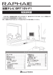
:fekifcjXe[=\Xkli\j
A
B
C
C
D
F
G
E
=`^li\(% M1039 headstock controls.
H
I
K
J
=`^li\)% M1039 table controls.
8%
9%
:%
;%
<%
=%
>%
?%
@%
A%
B%
Light Switch (110V only)
Power Switch
Belt Tension Lock
Torsion Spring
Lash Screw
Depth Stop
-5-
Belt Tension Lever
Scale
Table Height Crank Handle
Small Lock Lever
Large Lock Lever
D('*0()$Jg\\[;i`ccGi\jj
J8=<KP
J8=<KP
I<8;D8EL8C9<=FI<FG<I8K@E>D8:?@E<%
=8@CLI<KF=FCCFN@EJKIL:K@FEJ9<CFNN@CC
I<JLCK@EG<IJFE8C@EALIP%
Indicates an imminently hazardous situation which, if not avoided, WILL
result in death or serious injury.
Indicates a potentially hazardous situation which, if not avoided, COULD
result in death or serious injury.
Indicates a potentially hazardous situation which, if not avoided, MAY
result in minor or moderate injury.
EFK@:<
This symbol is used to alert the user to useful information about proper
operation of the equipment, and/or a situation that may cause damage
to the machinery.
(% I<8;K?IFL>?K?<<EK@I<D8EL8C9<=FI<JK8IK@E>D8:?@E<IP% Machinery presents serious
injury hazards to untrained users.
)% 8CN8PJLJ<8EJ@8GGIFM<;J8=<KP>C8JJ<JN?<EFG<I8K@E>D8:?@E<IP% Everyday eyeglasses only have impact resistant lenses—they are NOT safety glasses.
*% 8CN8PJN<8I8E@FJ?8GGIFM<;I<JG@I8KFIN?<EFG<I8K@E>D8:?@E<IPK?8KGIF;L:<J
;LJK% Wood dust is a carcinogen and can cause cancer and severe respiratory illnesses.
+% 8CN8PJLJ<?<8I@E>GIFK<:K@FEN?<EFG<I8K@E>D8:?@E<IP% Machinery noise can cause
permanent hearing damage.
,% N<8IGIFG<I8GG8I<C% DO NOT wear loose clothing, gloves, neckties, rings, or jewelry which
may get caught in moving parts. Wear protective hair covering to contain long hair and wear nonslip footwear.
-% E<M<IFG<I8K<D8:?@E<IPN?<EK@I<;#FILE;<IK?<@E=CL<E:<F=;IL>JFI8C:F?FC%
Be mentally alert at all times when running machinery.
.% FECP8CCFNKI8@E<;8E;GIFG<ICPJLG<IM@J<;G<IJFEE<CKFFG<I8K<D8:?@E<IP% Make
sure operation instructions are safe and clearly understood.
/% B<<G:?@C;I<E8E;M@J@KFIJ8N8P% Keep all children and visitors a safe distance from the work
area.
0% D8B<NFIBJ?FG:?@C;GIFF=% Use padlocks, master switches, and remove start switch keys.
('% E<M<IC<8M<N?<ED8:?@E<@JILEE@E>% Turn power F== and allow all moving parts to come
to a complete stop before leaving machine unattended.
-6-
D('*0()$Jg\\[;i`ccGi\jj
((%;FEFKLJ<@E;8E><IFLJ<EM@IFED<EKJ% DO NOT use machinery in damp, wet locations, or
where any flammable or noxious fumes may exist.
()%B<<GNFIB8I<8:C<8E8E;N<CCC@K% Clutter and dark shadows may cause accidents.
(+% 8CN8PJ;@J:FEE<:K=IFDGFN<IJFLI:<9<=FI<J<IM@:@E>D8:?@E<IP% Make sure switch is
in OFF position before reconnecting.
(,% D8@EK8@ED8:?@E<IPN@K?:8I<% Keep blades sharp and clean for best and safest performance.
Follow instructions for lubricating and changing accessories.
(-%D8B<JLI<>L8I;J8I<@EGC8:<8E;NFIB:FII<:KCP9<=FI<LJ@E>D8:?@E<IP%
(.%I<DFM<8;ALJK@E>B<PJ8E;NI<E:?<J% Make a habit of checking for keys and adjusting
wrenches before turning machinery FE.
(/% :?<:B=FI;8D8><;G8IKJ9<=FI<LJ@E>D8:?@E<IP% Check for binding and alignment of
parts, broken parts, part mounting, loose bolts, and any other conditions that may affect machine
operation. Repair or replace damaged parts.
(0% LJ<I<:FDD<E;<;8::<JJFI@<J% Refer to the instruction manual for recommended accessories.
The use of improper accessories may cause risk of injury.
)'%;FEFK=FI:<D8:?@E<IP% Work at the speed for which the machine or accessory was designed.
)(% J<:LI<NFIBG@<:<% Use clamps or a vise to hold the workpiece when practical. A secured
workpiece protects your hands and frees both hands to operate the machine.
))% ;FEFKFM<II<8:?% Keep proper footing and balance at all times.
)*% D8EPD8:?@E<JN@CC<A<:KK?<NFIBG@<:<KFN8I;K?<FG<I8KFI% Know and avoid conditions that cause the workpiece to "kickback."
)+% 8CN8PJCF:BDF9@C<98J<J@=LJ<; 9<=FI<FG<I8K@E>D8:?@E<IP%
),%9<8N8I<K?8K:<IK8@E;LJKD8P9<?8Q8I;FLJKFK?<I<JG@I8KFIPJPJK<DJF=
G<FGC<8E;8E@D8CJ#especially fine dust. Make sure you know the hazards associated with the
type of dust you will be exposed to and always wear a respirator approved for that type of dust.
-7-
J8=<KP
(*% LJ<8>IFLE;<;<OK<EJ@FE:FI;I8K<;=FIK?<D8:?@E<8DG<I8><% Undersized cords
overheat and lose power. Replace extension cords if they become damaged. DO NOT use extension
cords for 220V machinery.
D('*0()$Jg\\[;i`ccGi\jj
J8=<KP
8[[`k`feXcJX]\kp@ejkilZk`fej]fi;i`ccGi\jj\j
I<8;Xe[le[\ijkXe[k_`j
\ek`i\ `ejkilZk`fe dXelXc
Y\]fi\lj`e^k_`jdXZ_`e\%
J\i`flj g\ijfeXc `ealip
dXp fZZli `] jX]\kp Xe[
fg\iXk`feXc`e]fidXk`fe`j
efk le[\ijkff[ Xe[ ]fc$
cfn\[% ;F EFK i`jb pfli
jX]\kpYpefki\X[`e^
LJ<k_`jXe[fk_\idXZ_`e\ipn`k_ZXlk`fe
Xe[ i\jg\Zk% 8cnXpj Zfej`[\i jX]\kp ]`ijk#
Xj `k Xggc`\j kf pfli `e[`m`[lXc nfib`e^
Zfe[`k`fej%Efc`jkf]jX]\kp^l`[\c`e\jZXe
Y\ Zfdgc\k\Ç\m\ip j_fg \em`ifed\ek `j
[`]]\i\ek%=X`cli\kf]fccfn^l`[\c`e\jZflc[
i\jlck `e j\i`flj g\ijfeXc `ealip# [XdX^\
kf\hl`gd\ekfigffinfibi\jlckj%
(% <P<&=8:<&?8E;GIFK<:K@FE% A face shield used with safety glasses is recommended. Always
keep hands and fingers away from the drill bit. Never hold a workpiece by hand while drilling! DO
NOT wear gloves when operating the drill.
)% J<:LI@E>9@K% Properly tighten and securely lock the drill bit in the chuck.
*% :FII<:K9@K% Use only round, hex, or triangular shank drill bits, or tapered shank drill bits mated
with the appropriate sleeve.
+% 8;ALJK@E>B<PJ8E;NI<E:?<J% Remove all adjusting keys and wrenches before turning the
machine FE.
,% ;I@CC@E>J?<<KD<K8C% Never drill sheet metal unless it is securely clamped to the table.
-% JLI=8:<&NFIBG@<:<GI<G8I8K@FE% Never turn the drill press FE before clearing the table
of all objects (tools, scrap wood, etc.) DO NOT drill material that does not have a flat surface,
unless a suitable support is used.
.% ;8D8><;KFFCJ% Never use tools in poor condition. Dull or damaged cutting tools are hard to
control and may cause serious injury.
/% ;I@CCFG<I8K@FE% Never start the drill press with the drill bit pressed against the workpiece.
Feed the drill bit evenly into the workpiece. Back the bit out of deep holes. Turn the machine
F== and clear chips and scrap pieces with a brush. Shut power F==, remove drill bit, and clean
table before leaving the machine.
0% FG<I8K@E>JG<<;% Always operate your drill press at speeds that are appropriate for the drill bit
size and the material that you are drilling.
('% D8@EK<E8E:<&JG<<;:?8E><J% Never do maintenance or change speeds with the machine
plugged in.
((% DFLEK@E>NFIBG@<:<J% Use clamps or vises to secure workpiece before drilling. Position work
so you avoid drilling into the table.
()% K89C<CF:B% Make sure the table lock is tightened before starting the drill press.
-8-
D('*0()$Jg\\[;i`ccGi\jj
<C<:KI@:8C
(('M&))'MFg\iXk`fe
<C<:KI@:8C
The E:AB8AJ ModelM1039 is prewired for 110V operation, but may be rewired for 220V operation. To do this,
consult the wiring diagram in the back of this manual.
Always connect this machine to a dedicated circuit (wire,
breaker, plug, receptacle) with a verified ground, using
the recommended circuit breakers and plugs/receptacles
listed at the bottom of this page.
Never replace a circuit breaker with one of higher amperage without consulting a qualified electrician to ensure
compliance with wiring codes.@]pflXi\lejli\XYflk
k_\n`i`e^Zf[\j`epfliXi\XfigcXekfZfee\Zkpfli
dXZ_`e\kfXj_Xi\[Z`iZl`k#pfldXpZi\Xk\X]`i\_Xq$
Xi[ÇZfejlckXhlXc`]`\[\c\Zki`Z`Xekfi\[lZ\k_`ji`jb%
6-15 P
<ok\ej`fe:fi[j
6-15 R
=`^li\*% NEMA 5-15 and 6-15 plug wiring.
We do not recommend using an extension cord for 220V
operation. When it is necessary to use an extension cord,
use the following guidelines:
•
•
•
•
K_`j \hl`gd\ek dljk Y\ ^ifle[\[%
Le[\i ef Z`iZldjkXeZ\j j_flc[ k_\
^ifle[`e^ g`e Y\ i\dfm\[ ]ifd Xep
k_i\\$gife^\[ gcl^ fi j\i`flj `ealip
dXpfZZli%
Use cords rated for Standard Service
Never exceed a length of 50 feet
Ensure cord has a ground wire and pin
Do not use cords in need of repair
>ifle[`e^
This machine must be grounded! The electrical cord supplied with this machine comes with a grounding pin. Do
not remove it. If converting to 220V operation, always
use a plug with a ground pin. If your outlet does not
accommodate a ground pin, have it replaced by a qualified electrician or have an appropriate adapter installed.
Efk\1 N_\elj`e^XeX[Xgk\i#k_\X[Xgk\idljkY\
^ifle[\[%
Fg\iXk`e^MfckX^\
8dg;iXn
9i\Xb\iJ`q\
Gcl^&I\Z\gkXZc\
<ok\ej`fe:fi[
110V Operation
15 Amps
20A
NEMA 5-15
12 Gauge, NEMA 5-15
220V Operation
7.5 Amps
15A
NEMA 6-15
14 Gauge, NEMA 6-15
-9-
D('*0()$Jg\\[;i`ccGi\jj
J<KLG
LegXZb`e^
The E:AB8AJ Model M1039 has been carefully packaged for safe transporting. If you notice the machine has
been damaged, please contact your authorized E:AB
8AJ dealer immediately.
If any parts are missing, examine the packaging for the missing parts. For any missing
parts, find the part number in the back
of this manual and contact Woodstock
International, Inc. at (360) 734-3482 or at
k\Z_$jlggfik7j_fg]fo%Y`q
@em\ekfip
JL==F:8K@FE?8Q8I;
@dd\[`Xk\cp [`jZXi[ Xcc
gcXjk`Z YX^j Xe[ gXZb$
`e^ dXk\i`Xcj kf \c`d`$
eXk\Z_fb`e^&jl]]fZXk`fe
_XqXi[j]fiZ_`c[i\eXe[
Xe`dXcj%
The following is a description of the main components
shipped with the E:AB8AJ® Model M1039. Lay the
components out to inventory them.
J<KLG
Efk\1 Jfd\gXikjXe[_Xi[nXi\dXpXci\X[pY\
`ejkXcc\[fek_\dXZ_`e\%DXb\jli\kfZ_\Zbk_\
dXZ_`e\n_\epfllj\k_`j`em\ekfipc`jk%
9fo@em\ekfip=`^li\+ Hkp
8% Base ......................................................... 1
9% Table ........................................................ 1
:% Table Bracket .............................................. 1
;% Headstock .................................................. 1
<% Column ..................................................... 1
?Xi[nXi\Xe[KffcjEfkJ_fne • Large Lock Lever ..........................................1
• Small Lock Lever ..........................................1
• Crank handle ...............................................1
• Handle .......................................................1
• Arbor ........................................................1
• Drift Key ....................................................1
• Chuck ........................................................1
• Chuck Key ...................................................1
• Downfeed Handles.........................................3
• Lock Wrench ................................................1
• Pinion ........................................................1
• Belt Cover Knob............................................1
• Hex Wrench 3mm ..........................................1
• Hex Wrench 4mm ..........................................1
• Hex Wrench 5mm ..........................................1
• Hex Bolt M12-1.75 x 45mm ..............................4
LEGCL> gfn\i Zfi[ Y\]fi\ pfl [f
Xep Xjj\dYcp fi X[aljkd\ek kXjbj
Fk_\in`j\# j\i`flj g\ijfeXc `ealip kf
pflfifk_\ijdXpfZZli
B
A
C
D
E
=`^li\+% Large component inventory.
-10-
D('*0()$Jg\\[;i`ccGi\jj
DXZ_`e\GcXZ\d\ek
=cffiCfX[1 This machine distributes a
heavy load in a small footprint. Some floors
may require additional bracing to support
both machine and operator.
Nfib`e^:c\XiXeZ\j1 Consider existing and
anticipated needs, size of material to be
processed through the machine, and space
for auxiliary stands, work tables or other
machinery when establishing a location for
your drill press.
C`^_k`e^1 Lighting should be bright enough
to eliminate shadow and prevent eye strain.
:c\Xe`e^DXZ_`e\
The table and other unpainted parts of your
machine type are coated with a waxy grease
that protects them from corrosion during shipment. Clean this grease off with a solvent cleaner or citrus-based degreaser. DO NOT use chlorine-based solvents such as brake parts cleaner
or acetone—if you happen to splash some onto a
painted surface, you will ruin the finish.
LJ<_\cg\ijfigfn\ic`]k$
`e^\hl`gd\ekkfc`]kk_`j
[i`cc gi\jj% Fk_\in`j\#
j\i`flj g\ijfeXc `ealip
dXpfZZli%
8CN8PJ nfib `e n\cc$
m\ek`cXk\[Xi\Xj]Xi]ifd
gfjj`Yc\ `^e`k`fe jfliZ\j
n_\e lj`e^ jfcm\ekj kf
Zc\Xe dXZ_`e\ip% DXep
jfcm\ekj Xi\ kfo`Z n_\e
`e_Xc\[fi`e^\jk\[%Lj\
ZXi\ n_\e [`jgfj`e^
f] nXjk\ iX^j Xe[
kfn\cj kf Y\ jli\ k_\p
;F EFK Zi\Xk\ ]`i\ fi
\em`ifed\ekXc_XqXi[j%
D8B< pfli j_fg ÈZ_`c[
jX]\%É <ejli\ k_Xk pfli
nfibgcXZ\ `j `eXZZ\jj`Yc\
kf pfle^jk\ij Yp Zcfj`e^
Xe[ cfZb`e^ Xcc \ekiXeZ\j
n_\epflXi\XnXp%E<M<I
Xccfn lekiX`e\[ m`j`kfij `e
pfli j_fg n_\e Xjj\d$
Yc`e^# X[aljk`e^ fi fg\iXk$
`e^\hl`gd\ek%
-11-
J<KLG
E<M<I lj\ ^Xjfc`e\ fi
fk_\i g\kifc\ld$YXj\[
jfcm\ekj kf Zc\Xe n`k_%
Dfjk _Xm\ cfn ]cXj_
gf`ekj# n_`Z_ dXb\ k_\d
\oki\d\cp ]cXddXYc\%
8 i`jb f] \ogcfj`fe Xe[
Ylie`e^ \o`jkj `] k_\j\
gif[lZkjXi\lj\[%J\i`flj
g\ijfeXc`ealipdXpfZZli
`]k_`jnXie`e^`j`^efi\[
D('*0()$Jg\\[;i`ccGi\jj
Dflek`e^kfJ_fg=cffi
Although not required, we recommend that you mount
your new machine to the floor. Because this is an
optional step and floor materials may vary, floor mounting hardware is not included. Generally, you can either
bolt your machine to the floor or mount it on machine
mounts. Both options are described below. Whichever
option you choose it will be necessary to use a precison
level to level your machine.
9fck`e^kf:feZi\k\=cffij
J<KLG
Lag shield anchors with lag bolts (=`^li\,) and anchor
studs (=`^li\-) are two popular methods for anchoring
an object to a concrete floor. We suggest you research
the many options and methods for mounting your
machine and choose the best that fits your specific application.
=`^li\,% Typical lag shield anchor and lag
bolt.
EFK@:<
8eZ_fijkl[jXi\jkife^\iXe[dfi\g\idXe\ekXck\i$
eXk`m\jkfcX^j_`\c[XeZ_fij2_fn\m\i#k_\pn`ccjk`Zb
flkf]k_\]cffi#n_`Z_dXpZXlj\Xki`gg`e^_XqXi[`]
pfl[\Z`[\kfdfm\pflidXZ_`e\XkXcXk\igf`ek%
Lj`e^DXZ_`e\Dflekj
Using machine mounts, shown in =`^li\., gives the
advantage of fast leveling and vibration reduction. If you
choose to use machine mounts, attach them to the base
before assembling the drill press.
=`^li\ -% Typical anchor stud.
=`^li\.% Machine mount example.
-12-
D('*0()$Jg\\[;i`ccGi\jj
:fcldeXe[9Xj\
The column must be secured on the base to properly
assemble your drill press.
Kfj\Zli\k_\Zfcldekfk_\YXj\#[fk_\j\jk\gj1
(%
Place the column on the base and align the mounting holes.
)%
Secure the column to the base with the four M12-1.75
x 45 hex bolts, as shown in =`^li\/.
Hex Bolts
KXYc\9iXZb\k
The table bracket must be installed as described to properly assemble your drill press.
=`^li\/% Column secured to base.
Kf`ejkXcck_\kXYc\jlggfik#[fk_\j\jk\gj1
Place the pinion in the table bracket, as shown in
=`^li\0, so the pinion and gear teeth mesh together.
)%
Mark the top of the rack, as shown in =`^li\(', to
keep track of which end is up.
*%
Remove the column ring by loosening the setscrew,
and remove the rack.
J<KLG
(%
Continued on next page
=`^li\0% Pinion correctly installed in
table bracket.
Column
Ring
Marking
Location
Rack
=`^li\('% Marking the top of the rack.
-13-
D('*0()$Jg\\[;i`ccGi\jj
+%
Place the rack inside of the table bracket, mesh it
together with the pinion, and slide the table support/rack assembly over the column, as shown in
=`^li\((.
,%
Slide the column ring over the column with the beveled edge facing down (=`^li\()), fit the beveled
edge of the column ring over the rack, and tighten
the setscrew.
J<KLG
Efk\1 DXb\jli\k_\iXZb`jj\Xk\[]`idcp`ek_\
cfn\ii`e^Y\]fi\k`^_k\e`e^k_\j\kjZi\n%;fefk
fm\i$k`^_k\ek_\j\kjZi\nfipfldXpjgc`kk_\Zfc$
ldei`e^%
-%
Install the crank handle over the pinion shaft, and
tighten the setscrew in the crank handle against the
flat part of the pinion shaft.
.%
Thread the handle into the crank handle.
/%
Thread the large lock lever into the back of the
table bracket approximately three turns, for now.
0%
Thread the small lock lever into the front part of
the table bracket approximately three turns, for
now. The assembly should now be assembled as
shown in =`^li\(*.
=`^li\((% Sliding table bracket and rack
over column.
=`^li\()% Correct column ring
orientation.
Large Lock
Lever
Crank Handle
Small Lock
Lever
=`^li\(*% Handles and lock levers
installed.
-14-
D('*0()$Jg\\[;i`ccGi\jj
?\X[jkfZb
The headstock must be mounted on the column/base
assembly before the drill press can be operated. Moving
and installing the headstock is a two-person job, at the
very least. Although the headstock can be lifted directly
onto the column while upright, doing so is difficult and
potentially dangerous because of the heavy weight
involved. We recommend sliding the column into the
headstock, then tilting the entire assembly fully upright,
as described and shown in this section.
Kfdflekk_\_\X[jkfZbfekfk_\Zfclde#[fk_\j\
jk\gj1
Set the top piece of the headstock styrofoam packing approximately six feet away from the column/
base assembly.
)%
Remove the headstock from the box and place it on
the styrofoam packing piece you laid out in Jk\g(.
Efk\1 KfXmf`[[XdX^`e^k_\dXZ_`e\#Y\ZXi\]lc
efkkf_fc[k_\_\X[jkfZbYpk_\jn`kZ_fik_\kfg
gXikf]k_\Y\ckZfm\in_\ec`]k`e^%
*%
Carefully lay the column/base on its side.
+%
Slide the column all the way into the bottom of the
headstock (approximately 4"—6").
,%
Tilt the entire assembly up (see =`^li\(+) and
carefully position the drill press on its base in the
fully upright position.
-%
Center a tape or ruler on the base, and suspend a
plumb bob from the center of the headstock spindle
so it is over the tape/ruler as shown in =`^li\(,.
.%
Center the headstock directly over the base as indicated by the plumb bob and ruler.
/%
Tighten the two headstock setscrews to the column,
as shown in =`^li\(-.
=`^li\(+% Mounting the headstock.
=`^li\(,% Aligning headstock with base.
=`^li\(-% Securing the headstock.
-15-
J<KLG
(%
D('*0()$Jg\\[;i`ccGi\jj
;i`cc:_lZbXe[8iYfi
Chuck Key
The drill chuck attaches to the spindle by means of the
arbor, shown in =`^li\(.. Matched tapers on the arbor
and the inside of the chuck create a semi-permanent
assembly when properly joined.
MT4/JT3
Arbor
fXjj\dYc\k_\[i`ccZ_lZbXe[dflek`kkfk_\jg`e$
K
[c\#[fk_\j\jk\gj1
J<KLG
(%
Use mineral spirits to thoroughly clean the drill
chuck, arbor, and spindle sockets and dry all surfaces before assembly. Follow all safety warnings
on the container of the mineral spirits.=X`cli\kf
Zc\Xek_\dXk`e^jli]XZ\jdXpZXlj\k_\kXg\i\[
]`kkfcffj\e[li`e^fg\iXk`fe#i\jlck`e^`ej\gXiX$
k`feXe[XelejX]\Zfe[`k`fe%
)%
Use the chuck key to adjust the jaws of the drill
chuck until they are inside the drill chuck body.
*%
Place the drill chuck face down on a workbench.
The arbor has a short taper and a long taper. Place
the short taper into the socket in the back of the
drill chuck and tap it with a rubber or wooden mallet, as shown in =`^li\(/. If the chuck fails to
remain secure on the arbor, repeat Jk\gj( & *.
+%
Slide the arbor into the spindle socket while slowly
rotating the drill chuck. The socket has a rectangular pocket into which the tang (or flat portion of the
arbor shown in =`^li\(/) will fit.
,%
JT3 Drill
Chuck
Drift Key
=`^li\(.% Chuck components and tools.
Tang-Side
Up
=`^li\(/% Seating the arbor into the
chuck.
Using a rubber mallet, seat the chuck as shown in
=`^li\(0.
;FEFKlj\Xjk\\c_Xdd\ifek_\[i`ccZ_lZbkf
j\Xkk_\XiYfi`ekfk_\jg`e[c\%Pfln`cc[XdX^\k_\
Z_lZbXe[&fijg`e[c\#n_`Z_dXpdXb\k_\dlelj$
XYc\filejX]\%
=`^li\(0% Seating the arbor and chuck
into the spindle.
-16-
D('*0()$Jg\\[;i`ccGi\jj
;fne]\\[?Xe[c\jXe[
9\ck:fm\iBefY
The downfeed handles must be installed to properly operate the drill press.
Spindle
Hub
Belt Cover
Knob
Kf`ejkXcck_\[fne]\\[_Xe[c\j#[fk_\j\jk\gj1
(%
Thread the handles into the pinion hub, as shown in
=`^li\)', and tighten.
)%
Remove the screw that fastens the belt cover in
place and install the belt cover knob in its place (see
=`^li\)' for location).
=`^li\)'% Downfeed handles and belt
cover knob installed.
KXYc\
J<KLG
The table must be installed to properly support the
workpiece during operation.
Kf`ejkXcck_\kXYc\#[fk_\j\jk\gj1
(%
Insert the table shaft into the table bracket.
)%
Tighten the small locking lever to secure the table
in the table bracket. The table should now be
installed as shown in =`^li\)(.
C`^_k(('MFecp
=`^li\)(% Table installed.
The Model M1039 includes a light socket, [\j`^e\[]fi
(('Mlj\fecp. When the drill press is shipped from the
factory, a dust plug is installed in the socket.
Kf`ejkXccXc`^_kYlcY`ek_\[i`ccgi\jj#[fk_\j\jk\gj1
(%
Remove the dust plug from the light socket.
)%
Install a 60W or smaller light bulb in the location
shown in =`^li\)).
Light Socket
Access Here
K_\c`^_kjfZb\k`eZcl[\[n`k_
k_`j[i`ccgi\jj`j]fi(('MLJ<
FECP%@]k_\c`^_kjfZb\k`jlj\[
n_`c\fg\iXk`e^Xk))'M#k_\c`^_k
YlcYN@CC<OGCF;<#gfk\ek`Xccp
ZXlj`e^j\i`fljg\ijfeXc`ealip%
-17-
=`^li\))% Light socket access
(110V only).
D('*0()$Jg\\[;i`ccGi\jj
K\jkIle
Before installing a drill bit, test run the machine to isolate any problems that may occur.
(%
Plug the drill press into the power supply.
)%
Turn the drill press FE; if there is a problem, turn
the drill press F== immediately.
The drill press should run smoothly, with little or no
vibration or rubbing noises. Strange or unusual noises
should be investigated and corrected before operating
the machine further. See GX^\*' for troubleshooting
instructions.
J<KLG
I\Zfdd\e[\[
8[aljkd\ekj
For your convenience, the adjustments listed below have
been performed at the factory and no further setup is
required to operate your machine.
However, because of the many variables involved with
shipping, some of these adjustments may need to be
repeated to ensure optimum results. Keep this in mind as
you start to use your new drill press.
Step-by-step instructions for these adjustments can be
found in theJ<IM@:<section of this manual.
(% ;\gk_Jkfg:Xc`YiXk`feGX^\))% =\\[J_X]kJgi`e^K\ej`feGX^\).
-18-
D('*0()$Jg\\[;i`ccGi\jj
FG<I8K@FEJ
>\e\iXc
The Model M1039 will perform many types of operations
that are beyond the scope of this manual. Many of these
operations can be dangerous or deadly if performed
incorrectly.
The instructions in this section are written with the
understanding that the operator has the necessary knowledge and skills to operate this machine. @]XkXepk`d\
pflXi\\og\i`\eZ`e^[`]]`Zlck`\jg\i]fid`e^Xepfg\iX$
k`fe#jkfglj`e^k_\dXZ_`e\
If you are an inexperienced operator, we strongly recommend that you read books, trade articles, and/or seek
training from an experienced drill press operator before
performing any unfamiliar operations. 8Yfm\Xcc#pfli
jX]\kpj_flc[Zfd\]`ijk
I<8;Xe[le[\ijkXe[k_`j\ek`i\`ejkilZ$
k`fe dXelXc Y\]fi\ lj`e^ k_`j dXZ_`e\%
J\i`flj g\ijfeXc `ealip dXp fZZli `]
jX]\kpXe[fg\iXk`feXc`e]fidXk`fe`jefk
le[\ijkff[ Xe[ ]fccfn\[% ;F EFK i`jb
pflijX]\kpYpefki\X[`e^
@ejkXcc`e^&I\dfm`e^9`kj
Kf`ejkXccX[i`ccY`k#[fk_\j\jk\gj1
(%
UNPLUG THE DRILL PRESS!
)%
Open the drill chuck wide enough to accept the
shank of the drill bit.
*%
Insert the drill bit as far as possible into the chuck
WITHOUT allowing the chuck jaws to touch the fluted portion of the bit, and hand tighten the chuck.
8cnXpjn\XijX]\kp^cXjj\jn_\efg\i$
Xk`e^k_\[i`ccgi\jj%=X`cli\kfZfdgcp
dXpi\jlck`ej\i`fljg\ijfeXc`ealip%
Efk\1 DXb\jli\jdXccY`kjXi\efkkiXgg\[Y\kn\\e
k_\\[^\jf]knfaXnj2`]k_\pXi\#i\`ejkXcck_\
[i`ccY`kfi`kn`ccefkY\j\Zli\\efl^_kflj\%
+%
Final tighten the drill bit with the chuck key.
Kfi\dfm\X[i`ccY`k#[fk_\j\jk\gj1
(%
UNPLUG THE DRILL PRESS!
)%
Use the chuck key to open the drill chuck, and catch
the drill bit with a rag to protect your hands.
-19-
;FEFK`em\jk`^Xk\gifYc\djfiX[aljk
k_\ [i`cc gi\jj n_`c\ `k `j ilee`e^%
NX`klek`ck_\dXZ_`e\`jklie\[F==#
legcl^^\[ Xe[ Xcc nfib`e^ gXikj
_Xm\Zfd\kfXZfdgc\k\jkfgY\]fi\
gifZ\\[`e^
FG<I8K@FEJ
Any drill bit you install in the chuck must be tight enough
that it will not come loose during operation.
D('*0()$Jg\\[;i`ccGi\jj
:_ffj`e^Jg\\[j
Lj`e^k_\;i`cc9`kJg\\[:_Xikj
The charts shown on GX^\)' & GX^\)(are intended as
guides only. Always follow the manufacturer's speed recommendations if provided with your drill bits, cutters, or
hole saws. Exceeding the recommended speeds may be
dangerous.
8cnXpj\ejli\Y`kjXi\`ejkXcc\[gifg$
\icp9<=FI<klie`e^k_\dXZ_`e\FE%
=X`cli\kf]fccfnZfii\Zk[i`ccY`k`ejkXc$
cXk`fe gifZ\[li\j ZXe c\X[ kf j\i`flj
g\ijfeXc`ealip%
The speeds shown are intended to get you started. The
optimum speed will always depend on various factors,
including tool diameter, drilling pressure, material hardness, material quality, and desired finish.
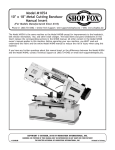
:_Xe^`e^Jg\\[j
The belts in the head of the drill press must be rearranged to change speeds. A chart under the belt cover
shows the belt positions needed to make the drill press
run at the desired speed.
FG<I8K@FEJ
KfZ_Xe^\jg\\[j#[fk_\j\jk\gj1
=`^li\)*% Loosening the lock knobs
(both sides).
(%
UNPLUG THE DRILL PRESS!
)%
Loosen the belt tension lock knobs (shown in =`^li\
)*) on both sides of the headstock, so the motor is
free to move.
*%
Rotate the belt tension lever counterclockwise, as
shown in =`^li\)+, to take tension off the V-belts.
+%
Locate the desired speed on the speed chart under
the belt cover and move the V-belts to the desired
V-grooves on the motor, idler, and spindle pulleys.
=fi<oXdgc\1 As indicated on the drill press speed
chart on GX^\)(, a belt combination of A-2 creates
670 RPM.
Efk\1 9fk_Y\ckjdXp_Xm\kfY\i\dfm\[Y\]fi\
Z\ikX`ejg\\[Z_Xe^\jZXeY\dX[\%
,%
Rotate the belt tension lever until the belts are
tight. Tighten both lock knobs.
-%
Close the cover before plugging in the machine.
-20-
=`^li\)+% Using the belt tension lever.
D('*0()$Jg\\[;i`ccGi\jj
FG<I8K@FEJ
-21-
FG<I8K@FEJ
D('*0()$Jg\\[;i`ccGi\jj
9
8
7
6
&
'
(
)
-/$%,-
30%%$$2),,02%33
HE>C9A:HE::9H:II>C<HGEB
&'&%GEB7:AI6")
'(&%GEB7:AI7")
()%%GEB7:AI6"(
)))%GEB7:AI8")
*+(%GEB7:AI7"(
++,%GEB7:AI6"'
,&'+%GEB7:AI9"(
-&)(%GEB7:AI8"'
.&+*%GEB7:AI7"&
&%'%*%GEB7:AI9"'
&&'(*%GEB7:AI8"&
&'((%%GEB7:AI9"&
=`^li\),. Belt configuration and speed settings.
-22-
D('*0()$Jg\\[;i`ccGi\jj
;i`cc`e^
Depth Nut
The Model M1039 is designed for drilling holes in wood
or metal. The basic operation of a drill press is lining up
your drill bit with the intended hole location, turning the
drill press FE, and using the down feed levers to move
the spinning drill bit into the workpiece.
=fijX]\fg\iXk`feXe[fgk`dldi\jlckj#`k`jm\ip
`dgfikXekkf]fccfnk_\j\^l`[\c`e\jXe[k_fj\feGX^\
)' n_\e[i`cc`e^1
:C<8I@E>:?@GJ1 Raise the drill bit often to clear chips
and cool the drill bit. This will ease the work of the drill
press motor and extend the life of your drill bits.
Depth
Stop Stud
Upper
Jam Nut
Depth Stop
Bracket
Lower
Jam Nut
=`^li\)-% Depth stop components.
J<:LI@E>NFIBG@<:<KFK89C<1 Secure the workpiece
to the table or in a vise that is secured to the table
before drilling.
GIFK<:K@E>K89C<1 Protect the table by placing the
workpiece on scrap wood, or center the location of the
hole to be drilled over the pocket in the table when
through drilling. Also, make use of the depth stop so that
the drill bit goes no deeper than necessary.
;\gk_Jkfg
The Model M1039 has a depth stop that allows you to drill
repeated non-through holes of same depth every time.
The depth stop consists of a stud attached to the quill,
with two hex nuts that can be lowered or raised on the
stud so the lower nut (depth nut) hits a stop bracket
when the drill bit is lowered. The upper hex nut (upper
jam nut) is then used to secure the depth nut in place
so it doesn't move with repeated operations. =`^li\)shows the various depth stop components.
Kfj\kk_\[\gk_jkfg#[fk_\j\jk\gj1
(%
Lower the drill bit to the required height.
)%
Thread the depth nut against the stop bracket.
-23-
FG<I8K@FEJ
LJ@E>:FII<:KJG<<;J1 Use the correct speed for the
diameter of the drill bit being used and the type of material being drilled. Refer to the ;i`cc9`kJg\\[:_Xikj on
GX^\)' & GX^\)(to help you choose the correct speed
for your application.
D('*0()$Jg\\[;i`ccGi\jj
*%
Lower the upper jam nut against the depth nut.
+%
Using wrenches, hold the depth nut in place and
tighten the upper jam nut against the depth nut.
Large Lock
Lever
Small Lock
Lever
Efk\1 K_\jZXc\fek_\[\gk_jkfgZXeY\i\ZXc`YiXk$
\[`]`k^\kjdfm\[fi_XjZ_Xe^\[j`eZ\k_\]XZkfip
j\kk`e^%I\]\ikf;\gk_Jkfg:Xc`YiXk`fefeGX^\
)-]fi`ejkilZk`fejfe_fnk_`j`j[fe\%
Location
Pin Nut
8[aljk`e^KXYc\
The table can be raised/lowered, rotated, and tilted
90º left or right. Table adjustment controls are shown in
=`^li\)..
FG<I8K@FEJ
KXYc\?\`^_k
(%
Loosen the large lock lever.
)%
Adjust the height.
*%
Lock the large lock lever.
KXYc\IfkXk`fe
(%
Loosen the small lock lever.
)%
Rotate the table as necessary.
*%
Lock the table small lock lever.
KXYc\K`ck
(%
Crank
Handle
Tighten the location pin nut to draw the location pin
out of the hole.
Efk\1 K_\cfZXk`feg`e`j]i`Zk`fe]`k`ek_\_fc\
kfcfZbk_\kXYc\Xk'²%N_\ei\`ejkXcc`e^#j\kk_\
kXYc\kf'²#YXZbk_\elkf]]#Xe[kXgk_\g`eYXZb
`ek_\_fc\%
)%
Loosen the lock bolt and tilt the table to the desired
angle (make sure table lock lever is locked, so the
table won't fall out).
*%
Tighten the lock nut bolt.
-24-
Lock
Bolt
=`^li\).% Typical table adjustment
controls.
D('*0()$Jg\\[;i`ccGi\jj
8iYfiI\dfmXc
The arbor can be removed to install other Morse Taper
tooling in the spindle. A drift key is included to help
remove the arbor or other tooling from the spindle.
Usually, once the chuck and arbor have been properly
mounted together, they are considered semi-permanent connections. (If you would like to install a different chuck, we recommend getting a new arbor for that
chuck.)
Both Slots
Aligned
Kfi\dfm\k_\[i`ccZ_lZbXe[XiYfi#[fk_\j\jk\gj1
(%
UNPLUG THE DRILL PRESS!
)%
Rotate the spindle handles until the drift key slot is
exposed in the side of the quill.
*%
Tighten the lower jam nut against the depth stop
bracket. The quill should not return up into the
head casting when the depth stop is adjusted this
way.
+%
Rotate the spindle until the inner drift key slot is
aligned with the outer slot, as shown in =`^li\)/.
You will see through the spindle when the slot is
properly aligned.
,%
Insert the drift key into the drift key slot.
-%
Hold a downfeed handle with one hand, and slightly
loosen the lower jam nut with the other hand. This
will allow the quill to rise, trapping the drift key.
.%
Hold the drill chuck with one hand, and tap on the
drift key with a rubber or wooden mallet, as shown
in =`^li\)0, until the arbor releases from the spindle taper.
/%
Hold a downfeed handle with one hand, and loosen
the lower jam nut with the other hand.
0%
Carefully retract the quill into the head stock.
=`^li\)/% Drift key slots aligned.
Drift Key
FG<I8K@FEJ
-25-
=`^li\)0% Arbor removal.
D('*0()$Jg\\[;i`ccGi\jj
D8@EK<E8E:<
>\e\iXc
Regular periodic maintenance on your E:AB8AJ®
Model M1039 will ensure its optimum performance. Make
a habit of inspecting your machine each time you use it.
:_\Zb]fik_\]fccfn`e^Zfe[`k`fejXe[i\gX`ifi
i\gcXZ\n_\ee\Z\jjXip1
Loose mounting bolts.
Loose chuck and/or arbor.
Worn switch.
Worn or damaged cords and plugs.
Damaged V-belt.
Any other condition that could hamper the safe
operation of this machine.
:c\Xe`e^
ClYi`ZXk`fe
Frequently blow-off sawdust with compressed air. This is
especially important for the internal working parts and
motor. Dust build-up around the motor is a sure way to
decrease its life span.
D8@EK<E8E:<
D8B< JLI< k_Xk pfli dXZ_`e\ `j
legcl^^\[ [li`e^ Xcc dX`ek\eXeZ\ gif$
Z\[li\j@]k_`jnXie`e^`j`^efi\[#j\i`$
fljg\ijfeXc`ealipdXpfZZli%
Occasionally it will become necessary to clean the internal parts with more than compressed air. To do this,
remove the table top and clean the internal parts with
a citrus cleaner or mineral spirits and a stiff wire brush
or steel wool. Make sure the internal workings are dry
before using the saw again, so that wood dust will not
accumulate. If any essential lubrication is removed during cleaning, relubricate those areas.
KXYc\#:fclde#9Xj\
Tables can be kept rust-free with regular applications
of products like SLIPIT. For long term storage you may
want to consider products like Boeshield T-9.
-26-
Since all bearings are sealed and permanently lubricated, simply leave them
alone until they need to be replaced. Do
not lubricate them.
M$9\ckj
Inspect regularly for tension and wear.
Check pulleys to ensure that they are
properly aligned. See :_Xe^`e^Jg\\[j
on GX^\(0 for more information about
removing/installing belts if you need help
replacing the belts.
D('*0()$Jg\\[;i`ccGi\jj
J<IM@:<
>\e\iXc
This section covers the most common service adjustments
or procedures that may need to be made during the life
of your machine.
If you require additional machine service not included
in this section, please contact Woodstock International
Technical Support at (360) 734-3482 or send e-mail to:
k\Z_$jlggfik7j_fg]fo%Y`q.
;\gk_Jkfg:Xc`YiXk`fe
The drill press comes fitted with a depth stop to use
when drilling multiple holes at the same depth. The scale
on this depth stop can be calibrated if it ever becomes
incorrect.
D8B< JLI< k_Xk pfli dXZ_`e\ `j
legcl^^\[ [li`e^ Xcc j\im`Z\ gifZ\$
[li\j @] k_`j nXie`e^ `j `^efi\[# j\i`$
fljg\ijfeXc`ealipdXpfZZli%
KfZXc`YiXk\k_\[\gk_jkfg#[fk_\j\jk\gj1
(%
Loosen the lower jam nut and calibration nut shown
in=`^li\*'.
)%
Use the calibration nut to zero the depth stop scale
with the depth stop bracket.
*%
Hold the depth stop at zero, and tighten the lower
jam nut to hold the depth stop in position.
+%
Test the depth stop by measuring how far the spindle actually moves with respect to where you set
the depth stop.
Depth Stop
Bracket
Calibration
Nut
Lower
Jam Nut
=`^li\*'% Depth stop calibration.
J<IM@:<
-27-
D('*0()$Jg\\[;i`ccGi\jj
=\\[J_X]kJgi`e^
K\ej`fe
Spring
Cover Lock
Slot
The feed shaft return spring is adjusted at the factory;
however, during the life of the drill press you may want
to adjust the feed shaft return spring so the return pressure suits your operating needs.
J<IM@:<
Kf X[aljk k_\ ]\\[ j_X]k jgi`e^ k\ej`fe# [f k_\j\
jk\gj1
Spring lock
cover
(%
UNPLUG THE DRILL PRESS!
)%
Wipe off any oil on the spring lock cover (=`^li\*()
so it does not slip in your fingers when you hold the
cover from spinning.
*%
While holding the spring lock cover against the side
of the head stock so the cover stays splined with the
locking lug; loosen the jam nut and loosen the cover
nut approximately 1⁄4" (see =`^li\*)).
+%
Put on heavy leather gloves to protect your hands
from possible lacerations if the spring uncoils during
the next step.
,%
Pull the cover outward just enough to disengage the
spring-cover lock slot from the locking lug.
Jam nut and
cover nut
=`^li\*(% Feed shaft spring.
Efk\1 @k`j`dgfikXekkfb\\gX^ff[^i`g[li`e^k_`j
jk\g%C\kk`e^^ff]k_\Zfm\in`ccZXlj\k_\jgi`e^
kfiXg`[cpleZf`c%
=`^li\*)% Loosening spring nut.
-%
Rotate the cover counterclockwise to increase spring
tension, or let the cover slowly unwind in the clockwise direction to reduce spring tension.
.%
Engage the next available spring-cover lock slot with
the locking lug and hold the spring lock cover tightly
against the side of the head stock.
8 _`^_ k\ej`fe Zf`c\[ jgi`e^ `j le[\i$
e\Xk_k_\Zfm\i%Glkfe_\Xmpc\Xk_\i
^cfm\j kf gifk\Zk pflij _Xe[j ]ifd
gfjj`Yc\ cXZ\iXk`fej n_\e i\dfm`e^
k_\Zfm\i%
/%
Snug the cover nut against the spring cover just
until the nut stops, and then back off the nut
approximately 1⁄3 turn, or just enough so there is no
binding at complete spindle travel.
0% Hold the cover nut and tighten the jam nut against
the cover nut.
-28-
D('*0()$Jg\\[;i`ccGi\jj
<c\Zki`ZXc:fdgfe\ekj
=`^li\**% Power and light switch wiring.
=`^li\*,% Motor junction box wiring.
=`^li\*+% 110V light socket.
=`^li\*-% Wiring diagram on inside of junction
box cover.
J<IM@:<
-29-
-30-
Hot
220 VAC
Hot
NEMA 6-15 Plug
(As recommended)
G
Hot
110 VAC
Ground
NEMA 5-15 Plug
(As recommended)
W
G
Neutral
Ground
<c
7`
Li
7`
Li
<c
L=>I:
<G::C
Li
Li
7g
GY
G:9
7a
7`
Li
LIGHT
SOCKET
7`
Li
LIGHT SOCKET
AND PLUG
220V WIRING
POWER SWITCH
7GDLC
7AJ:
Li
Li
110V WIRING
POWER SWITCH
LIGHT SWITCH
7`
Li
LIGHT SWITCH
COLOR KEY
Li
Li
7A68@
7`
7`
<c
Li
GY
<c
7c
Li
7a
GY
<c
7c
7a
(
)
'
&
)
(
'
&
MOTOR
1-1/2 HP, 1725 RPM
MOTOR
1-1/2 HP, 1725 RPM
XcnXpjlj\k_\[`X^iXdfek_\`ej`[\f]k_\aleZk`feYfoZfm\in_\ei\n`i`e^pflidfkfi
EFK@:<1K_\j\dfkfin`i`e^[`X^iXdjXi\Zlii\ekXkk_\k`d\f]gi`ek`e^2_fn\m\i#
7`
Li
7`
Li
J<IM@:<
D('*0()$Jg\\[;i`ccGi\jj
D('*0()$Jg\\[;i`ccGi\jj
KiflYc\j_ffk`e^
This section covers the most common problems and corrections with this type of
machine. N8IE@E>;FEFKdXb\XepX[aljkd\ekjlek`cgfn\i`j[`jZfee\Zk\[Xe[
dfm`e^gXikj_Xm\Zfd\kfXZfdgc\k\jkfg
GIF9C<D
GFJJ@9C<:8LJ<
:FII<:K@M<8:K@FE
Machine does not
start or a breaker
trips.
1.
1.
2.
3.
4.
5.
6.
7.
Machine stalls or is
underpowered.
Plug or receptacle at fault or wired
incorrectly.
Start capacitor is faulty.
Motor connection is wired Incorrectly.
Power supply is faulty, or is switched
OFF.
Safety switch key at fault.
6.
7.
8.
Motor is at fault.
8.
1.
2.
Incorrect spindle speed.
Bit is too large for task.
1.
2.
3.
4.
Bit is dull.
Low power supply voltage.
5.
6.
Belt(s) is slipping.
Plug or receptacle is at fault.
7.
8.
9.
Motor connection wired incorrectly.
Pulley slipping on shaft.
Motor bearings are at fault.
11. Motor at fault.
Re-check spindle speed.
Use smaller drill bits. Reduce feed rate and spindle speed.
3.
Sharpen/replace bit.
4.
Make sure hot lines and grounds are operational
w/correct voltage.
5.
Replace bad belts, align pulleys, and re-tension.
6.
Test power plug and receptacle for good contact
and correct wiring.
7.
Correct motor wiring (see GX^\)0).
8.
Replace loose pulley and shaft.
9.
Rotate motor shaft for noisy or burnt bearings,
repair/replace as required.
10. Clean inside/outside of motor, let cool, and
reduce workload on machine.
11. Test, repair or replace motor.
1.
2.
Belt is loose or worn.
Pulley for spindle shaft or motor is
slipping on shaft.
1.
2.
3.
Bit slips in chuck.
3.
1.
2.
Motor or component is loose.
Belts are slapping belt cover.
1.
2.
3.
4.
V-belt(s) is worn or is loose.
Motor fan is rubbing on fan cover.
3.
4.
5.
Pulley is loose.
5.
6.
6.
7.
Machine is incorrectly mounted to
floor.
Chuck is at fault.
8.
Motor bearings are at fault.
8.
9.
Spindle bearings at fault.
9.
-31-
7.
Replace and/or adjust belt.
To resecure pulley, do these steps:
a. UNPLUG DRILL PRESS.
b. Remove setscrew on slipping pulley.
c. Align flats on pulley shaft with
setscrew hole.
d. Reinstall and tighten setscrew.
Tighten bit; inspect bit for burrs or other obstructions that might interfere with clamping surface.
Inspect, replace damaged bolts/nuts. Re-tighten.
Replace/realign belts with a new matched set,
and retension belts (refer to GX^\(0).
Replace belts.
Replace/repair dented fan cover, and replace
loose or damaged fan.
Remove pulley, replace with key as required, and
re-install securely.
Re-check floor mounting hardware; tighten.
Replace out-of-round chuck, use appropriate feed
rate and drilling RPM.
Check bearings, replace motor or bearings as
required.
Replace bearing.
J<IM@:<
Machine has vibration or noisy operation.
5.
ON/OFF switch is faulty.
Cable or wiring is open or has high
resistance.
10. Motor has overheated.
Drilling stops, but
motor still operates.
2.
3.
4.
Test power plug and receptacle for good contact
and correct wiring.
Replace capacitor.
Correct motor wiring (see GX^\)0).
Make sure all hot lines and grounds are operational and have correct voltage on all legs.
Install or replace safety key, or replace switch
assembly.
Replace faulty switch.
Troubleshoot wires for internal or external breaks,
check for disconnected or corroded connections
and repair or replace wiring.
Test, repair or replace motor.
D('*0()$Jg\\[;i`ccGi\jj
GIF9C<D
GFJJ@9C<:8LJ<
:FII<:K@M<8:K@FE
Chuck wobbles or
is loose on spindle
shaft.
1.
Foreign material is stuck between
chuck-to-spindle mating surface.
1.
2.
Damaged chuck.
2.
1.
1.
2.
Quill shaft is gummy with sawdust and
oil.
Feed shaft return spring is weak.
3.
Quill deflection screw is binding quill.
3.
Quill has excessive
deflection.
1.
2.
Quill shaft is at fault.
Quill and/or bearings are worn.
1.
2.
Adjust quill screw.
Replace quill and/or bearings.
Holes drilled at an
angle.
1.
Table is not at 90 degrees.
1.
Adjust table angle (see GX^\)*).
Drill bit wobbles,
holes are oversized.
1.
Drill bit incorrectly installed.
1.
Remove drill bit and reinstall.
J<IM@:<
Spindle does not
retract completely
in uppermost position or it binds.
-32-
2.
Remove chuck and clean and de-burr tapered
chuck and spindle mating surfaces, then reassemble.
Replace.
Clean gummy substance with penetrating oil and
lubricate with a light coat of oil.
Increase feed shaft return spring tension as
described on GX^\)..
Loosen jam nut, and slightly turn out screw where
quill binds. Retighten jam nut and recheck for
binding and looseness at all spindle locations.
D('*0()$Jg\\[;i`ccGi\jj
KXYc\&:fclde9i\Xb[fne
('0
(',
('*
('('/
(.
('.
()'
())
((('
((. ((/
((-
((0
()(
(((
((*
(*
()*
(()
((+
((,
(,
(+
()+
G8IKJ
-33-
D('*0()$Jg\\[;i`ccGi\jj
?\X[jkfZb9i\Xb[fne
-,
-*
)
-(/
,0
,+
-+
,) ,(
-'
,'
+*
+)
*
,*
+(
()
,-
+'
,.
,/
))
((
(' 0
-(
-)
,,
+,"*
+0
*
+,"&
*0
)
+,"'
+,")
+,"(
(
/
'
-.
+,
,
()
.
+.
.+
+/
*/
..
.*
++
.-
-0
-/
/.
.)
//
/+
(0
/*
/)
0' .( /0
0)
)+
/(
//,
)'
0(
)(
./$(
./$)
.0
./
('+
.'
0*
0+
**
*.
(
+-
)*
/'
)0.
(''
('(
0-
(')
)-$(
)-$)
.,
),
./$*
*)
+
*-
('+
*(
/'
00
*'
).
0/
0,$(
)0
0,
)/
*+
G8IKJ
*,
-34-
D('*0()$Jg\\[;i`ccGi\jj
GXikjC`jk
PART#
DESCRIPTION
REF
PART#
DESCRIPTION
XLABEL04
XM1039002
XLABEL08H
XLABEL06
XPSB14M
XM1039006
XPN03M
XM1039008
XM1039009
XPW02M
XPS05M
XPN31M
XPLW10
XPN03M
XPSS21M
XM1039016
XM1039017
XPR21M
XM1039019
XM1039020
XM1039021
XM1039022
XM1039023
XM1039024
XM1039025
XPWRCRD110L
XM1039026-1
XM1039026-2
XM1039027
XPAW04M
XPAW03M
XM1039030
XM1039031
XM1039032
XM1039033
XM1039034
XM1039035
XM1039036
XM1039037
XP6206
XM1039039
XM1039040
XP6206
XM1039042
XM1039043
XPR37M
XP6207
XM1039046
XP6207
XPR26M
XM1039049
XM1039050
XM1039051
XPVA32
XM1039053
ELECTRICITYLABEL
CLOSEDOORHORIZLABEL
READMANUALLABEL
RESP/GLASSESLABEL
CAPSCREWM8-1.25X20
QUILLCLAMP
HEXNUTM8-1.25
DEPTHSTOPSCALESTUD
DEPTHSTOPBRACKET
FLATWASHER5MM
PHLPHDSCRM5-.8X8
HEXNUTM12-1.5
LOCKWASHER3/4
HEXNUTM8-1.25
SETSCREWM8-1.25X25
INDICATOR
DEGREESCALE
INTRETAININGRING35MM
STRAINRELIEF
UNPLUGLABEL
DPLIGHTSLABEL
SHOPFOXBLACK/ALLABEL
SPEEDCHARTM1039
MACHINEIDLABEL
SLEEVEMT#4
POWERCORD110V,LONG
WIREGASKET
MOTORCORD
DRIFTKEY
HEXWRENCH4MM
HEXWRENCH3MM
LIGHTDUSTPLUG
LIGHTSOCKET
LIGHTBASE
SWITCHBOX
CHUCKKEY
CHUCKJT3X1-16MM
ARBORJT3xMT#4
SPINDLE
BALLBEARING6205
SPINDLESLEEVE
RUBBERWASHER
BALLBEARING6206
TABWASHER
ROUNDNUT
EXTRETAININGRING32MM
BALLBEARING6207
SPACER
BALLBEARING6207
INTRETAININGRING52MM
PULLEYINSERT
SPINDLEPULLEY
PULLEYNUT
V-BELTA-324L320
PULLEYCOVER
54
55
56
57
58
59
60
61
62
63
64
65
66
67
67-1
67-2
67-3
67-4
67-5
68
69
70
71
72
73
74
75
76
77
78
78-1
78-2
78-3
79
80
81
82
83
84
85
86
87
88
89
90
91
92
93
94
95
95-1
96
97
98
99
XM1039054
XPW02M
XPS09M
XPS14M
XPW03M
XM1039059
XPR02M
XP6202
XM1039062
XPVA26
XPSS01M
XPK23M
XM1039066
XM1039067
XM1039067-1
XM1039067-2
XM1039067-3
XM1039067-4
XM1039067-5
XPN02M
XPW04M
XM1039070
XM1039071
XM1039072
XM1039073
XPB03M
XM1039075
XM1039076
XPS14M
XPSW08
XM1039078-1
XPHTEK6M
XM1039078-3
XM1039079
XPS08M
XM1039081
XM1039082
XM1039083
XPN31M
XM1039084
XPN02M
XPN03M
XPW01M
XPB07M
XM1039091
XM1039092
XPR05M
XM1039088
XM1039089
XPB01M
XM1039095-1
XM1039096
XM1039097
XM1039098
XM1039099
ROUNDKNOBM5-.8
FLATWASHER5MM
PHLPHDSCRM5-.8X10
PHLPHDSCRM6-1X12
FLATWASHER6MM
CENTERPULLEY
EXTRETAININGRING14MM
BALLBEARING6202
CENTERSHAFT
V-BELTA-264L260
SETSCREWM6-1X10
KEY5X5X25
MOTORPULLEY
MOTOR1-1⁄2HP
MOTORFAN
CAPACITORCOVER
SCAPACITOR400MFD250VAC
WIRINGBOXCOVER
FANCOVER
NUTM10-1.5
FLATWASHER10MM
MOTORBASE
SLIDEBAR(RIGHT)
SLIDEBAR(LEFT)
SHIFTER
HEXBOLTM8-1.25X16
HEADSTOCK
CLAMPCORD
PHLPHDSCRM6-1X12
SWITCH110VWITHKEY
SWITCHPLATE
TAPSCREWM4X16
SWITCHKEY
SWITCH(LIGHT)
PHLPHDSCRM5-.8X12
SPRINGCOVER
FLATCOILSPRING
SPRINGCAP
HEXNUTM12X1.5
SPECSETSCREWM10-1.5X30
HEXNUTM10-1.5
HEXNUTM8-1.25
FLATWASHER8MM
HEXBOLTM8-1.25X25
KNOBBOLTM10-1.5X35
SHIFTERBAR
EXTRETAININGRING15MM
ROLLPIN8X105MM
SETSCREWM10-1.5X30
HEXBOLTM10-1.5X30
PLASTICLOCKCAP
STAFFGAUGE
FEEDHANDLEKNOBM12-1.75
HANDLE
HANDLEBODY
-35-
G8IKJ
REF
1
2
3
4
5
6
7
8
9
10
11
12
13
14
15
16
17
18
19
20
21
22
23
24
25
26
26-1
26-2
27
28
29
30
31
32
33
34
35
36
37
38
39
40
41
42
43
44
45
46
47
48
49
50
51
52
53
D('*0()$Jg\\[;i`ccGi\jj
REF
PART#
DESCRIPTION
REF
PART#
DESCRIPTION
100
101
102
103
104
105
106
107
108
109
110
111
112
XPK07M
XM1039101
XM1039102
XPSS01M
XPRP04M
XM1039105
XM1039106
XM1039107
XM1039108
XM1039109
XM1039110
XM1039111
XM1039112
KEY6X6X20
SCALERING
FEEDSHAFT
SETSCREWM6-1.0X10
ROLLPIN4X24
RACKRING
WORMGEAR
GEAR
LARGELOCKINGLEVER
TABLE
TABLEARMBRACKET
SMALLLOCKINGLEVER
HEXBOLTM20-2.5x45
113
114
115
116
117
118
119
120
121
122
123
124
XPW13
XM1039114
XPN01M
XM1039116
XPSS01M
XM1039118
XM1039119
XM1039120
XM1039121
XM1039122
XPB27M
XM1039124
FLATWASHER3/4
PIN
HEXNUTM6-1
SHAFT
SETSCREWM6-1X10
HANDLEARM
HANDLE
TABLEBRACKET
COLUMN
RACK
HEXBOLTM12-1.75X30
BASE
JX]\kpCXY\cGcXZ\d\ek
G8IKJ
K_\jX]\kpcXY\cjfek_`jdXZ_`e\nXieXe[`e[`ZXk\_fnkfgifk\Zkk_\fg\iXkfifiYpjkXe[\i]ifd
dXZ_`e\_XqXi[j%K_\dXZ_`e\fne\iDLJKdX`ekX`ek_\fi`^`eXccXY\ccfZXk`feXe[i\X[XY`c`kp%@]
XcXY\c`ji\dfm\[fiY\Zfd\jlei\X[XYc\#I<GC8:<k_\cXY\cY\]fi\lj`e^k_\dXZ_`e\%=fie\n
cXY\cj#ZfekXZkNff[jkfZb@ek\ieXk`feXcXk*-' .*+$*+/)finnn%j_fg]fo%Y`q%
-36-
-37-
NXiiXekp
N8II8EKP
Nff[jkfZb@ek\ieXk`feXc#@eZ%nXiiXekjXccJ_fg=fodXZ_`e\ipkfY\]i\\f][\]\Zkj]ifdnfibdXej_`g
Xe[dXk\i`Xcj]fiXg\i`f[f]knfp\Xij]ifdk_\[Xk\f]fi`^`eXcgliZ_Xj\Ypk_\fi`^`eXcfne\i%
K_`jnXiiXekp[f\jefkXggcpkf[\]\Zkj[l\[`i\Zkcpfi`e[`i\Zkcpkfd`jlj\#XYlj\#e\^c`^\eZ\fi
XZZ`[\ekj#cXZbf]dX`ek\eXeZ\#fii\`dYlij\d\ekf]k_`i[gXikp\og\ej\j`eZlii\[%
Nff[jkfZb@ek\ieXk`feXc#@eZ%n`cci\gX`ifii\gcXZ\#Xk`kj\og\ej\Xe[Xk`kjfgk`fe#k_\J_fg=fo
dXZ_`e\fidXZ_`e\gXik#n_`Z_`eefidXclj\_Xjgifm\ekfY\[\]\Zk`m\#gifm`[\[k_Xkk_\fi`^`eXc
fne\ii\kliejk_\gif[lZkgi\gX`[kfXJ_fg=fo]XZkfipj\im`Z\Z\ek\in`k_giff]f]k_\`igliZ_Xj\
f]k_\gif[lZkn`k_`eknfp\Xij#Xe[gifm`[\jNff[jkfZb@ek\ieXk`feXc#@eZ%i\XjfeXYc\fggfikle`kpkf
m\i`]pk_\Xcc\^\[[\]\Zkk_ifl^_`ejg\Zk`fe%@]`k`j[\k\id`e\[k_\i\`jef[\]\Zk#fik_Xkk_\[\]\Zk
i\jlck\[]ifdZXlj\jefkn`k_`ek_\jZfg\f]Nff[jkfZb@ek\ieXk`feXc@eZ%jnXiiXekp#k_\ek_\fi`^`eXc
fne\idljkY\Xik_\Zfjkf]jkfi`e^Xe[i\klie`e^k_\gif[lZk%
K_`j`jNff[jkfZb@ek\ieXk`feXc#@eZ%jjfc\ni`kk\enXiiXekpXe[XepXe[XccnXiiXek`\jk_XkdXp
Y\`dgc`\[YpcXn#`eZcl[`e^Xepd\iZ_XekXY`c`kpfi]`ke\jj#]fiXepgXik`ZlcXigligfj\#Xi\_\i\Yp
c`d`k\[kfk_\[liXk`fef]k_`jni`kk\enXiiXekp%N\[fefknXiiXekk_XkJ_fg=fodXZ_`e\ipZfdgc`\j
n`k_k_\gifm`j`fejf]XepcXnfiXZkj%@eef\m\ekj_XccNff[jkfZb@ek\ieXk`feXc#@eZ%jc`XY`c`kple[\i
k_`jnXiiXekp\oZ\\[k_\gliZ_Xj\gi`Z\gX`[]fik_\gif[lZk#Xe[Xepc\^XcXZk`fejYifl^_kX^X`ejk
Nff[jkfZb@ek\ieXk`feXc#@eZ%j_XccY\ki`\[`ek_\JkXk\f]NXj_`e^kfe#:flekpf]N_XkZfd%N\j_Xcc
`eef\m\ekY\c`XYc\]fi[\Xk_#`eali`\jkfg\ijfejfigifg\ikpfi]fi`eZ`[\ekXc#Zfek`e^\ek#jg\Z`Xcfi
Zfej\hl\ek`Xc[XdX^\jXi`j`e^]ifdk_\lj\f]fligif[lZkj%
<m\ip\]]fik_XjY\\edX[\kf\ejli\k_XkXccJ_fg=fodXZ_`e\ipd\\kj_`^_hlXc`kpXe[[liXY`c`kp
jkXe[Xi[j%N\i\j\im\k_\i`^_kkfZ_Xe^\jg\Z`]`ZXk`fejXkXepk`d\Y\ZXlj\f]fliZfdd`kd\ekkf
Zfek`elfljcp`dgifm\k_\hlXc`kpf]fligif[lZkj%
-38-
D('*0()$Jg\\[;i`ccGi\jj
NXiiXekpI\^`jkiXk`fe
Name ___________________________________________________________________________________
Street __________________________________________________________________________________
City _________________________ State ___________________________Zip ________________________
Phone # ______________________ Email___________________________Invoice # ___________________
Model #_________Serial #______________Dealer Name__________________Purchase Date___________
K_\]fccfn`e^`e]fidXk`fe`j^`m\efeXmfclekXipYXj`j%@kn`ccY\lj\[]fidXib\k`e^gligfj\jkf_\cglj
[\m\cfgY\kk\igif[lZkjXe[j\im`Z\j%F]Zflij\#Xcc`e]fidXk`fe`jjki`ZkcpZfe]`[\ek`Xc%
(%
)%
CUT ALONG DOTTED LINE
*%
How did you learn about us?
_____ Advertisement
_____ Mail Order Catalog
_____ Friend
_____ Website
____ Local Store
____ Other:
How long have you been a woodworker/metalworker?
_____ 0-2 Years
_____ 2-8 Years
____ 8-20 Years
_____ 20+ Years
How many of your machines or tools are EZab8aj?
_____ 0-2
_____ 3-5
____ 6-9
_____ 10+
+%
Do you think your machine represents a good value?
_____ Yes
____ No
,%
Would you recommend EZab8aj products to a friend?
_____ Yes
____ No
-%
What is your age group?
_____ 20-29
_____ 50-59
.%
/%
What is your annual household income?
_____ $20,000-$29,000
_____ $30,000-$39,000
_____ $50,000-$59,000
_____ $60,000-$69,000
____ 40-49
____ 70+
____ $40,000-$49,000
____ $70,000+
Which of the following magazines do you subscribe to?
____
____
____
____
____
____
____
____
____
____
0%
_____ 30-39
_____ 60-69
Cabinet Maker
Family Handyman
Hand Loader
Handy
Home Shop Machinist
Journal of Light Cont.
Live Steam
Model Airplane News
Modeltec
Old House Journal
____
____
____
____
____
____
____
____
____
____
Popular Mechanics
Popular Science
Popular Woodworking
Practical Homeowner
Precision Shooter
Projects in Metal
RC Modeler
Rifle
Shop Notes
Shotgun News
____
____
____
____
____
____
____
____
____
Today’s Homeowner
Wood
Wooden Boat
Woodshop News
Woodsmith
Woodwork
Woodworker West
Woodworker’s Journal
Other:
Comments:VVVVVVVVVVVVVVVVVVVVVVVVVVVVVVVVVVVVVVVVVVVVVVVVVVVVVVVVVVVVVVVVVV
VVVVVVVVVVVVVVVVVVVVVVVVVVVVVVVVVVVVVVVVVVVVVVVVVVVVVVVVVVVVVVVVVVVVVVVVVVVVV
VVVVVVVVVVVVVVVVVVVVVVVVVVVVVVVVVVVVVVVVVVVVVVVVVVVVVVVVVVVVVVVVVVVVVVVVVVVVV
VVVVVVVVVVVVVVVVVVVVVVVVVVVVVVVVVVVVVVVVVVVVVVVVVVVVVVVVVVVVVVVVVVVVVVVVVVVVV
VVVVVVVVVVVVVVVVVVVVVVVVVVVVVVVVVVVVVVVVVVVVVVVVVVVVVVVVVVVVVVVVVVVVVVVVVVVVV
FOLD ALONG DOTTED LINE
Place
Stamp
Here
NFF;JKF:B@EK<IE8K@FE8C@E:%
G%F%9FO)*'0
9<CC@E>?8D#N80/)).$)*'0
FOLD ALONG DOTTED LINE
TAPE ALONG EDGES--PLEASE DO NOT STAPLE