1
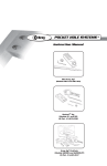
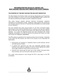
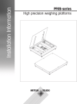
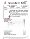
®
ROUTER TABLE
ITEM W2000
OPERATING MANUAL
P.O. Box 2309
Bellingham, WA 98227
COPYRIGHT © 1995 BY WOODSTOCK INTERNATIONAL, INC., REG.# TX 3 360-515
WARNING: NO PORTION OF THIS MANUAL MAY BE REPRODUCED IN ANY SHAPE
OR FORM WITHOUT THE WRITTEN APPROVAL OF WOODSTOCK INTERNATIONAL, INC.
PRINTED IN TAIWAN
REVISED FEBRUARY 2004
TABLE OF CONTENTS
I.
II.
III.
IV.
INTRODUCTION ....................................................................................................................................2
A.
SAFETY INSTRUCTIONS FOR ALL TOOLS ............................................................................2
B.
ADDITIONAL SAFETY RULES FOR THE REBEL® ................................................................3
C.
COMMENTARY ............................................................................................................................4
D.
UNPACKING ..................................................................................................................................5
E.
PIECE INVENTORY ......................................................................................................................5
ASSEMBLY ..............................................................................................................................................6
A.
STAND ............................................................................................................................................6
B.
FENCE ............................................................................................................................................7
C.
SAFETY GUARD ..........................................................................................................................8
D.
MITER GAUGE ..............................................................................................................................9
E.
ELECTRICAL SWITCH (OPTIONAL) ........................................................................................9
F.
MOUNTING THE ROUTER..........................................................................................................9
G.
WIRING THE ROUTER ..............................................................................................................10
ADJUSTMENTS ....................................................................................................................................11
A.
ROUTER TABLE INSERT ..........................................................................................................11
B.
FENCE ADJUSTMENT................................................................................................................12
C.
SAFETY GUARD ........................................................................................................................13
D.
MITER GAUGE ............................................................................................................................14
OPERATIONS ........................................................................................................................................15
A.
SITE PLANNING..........................................................................................................................15
B.
WORKING HEIGHT ....................................................................................................................15
C.
SAFETY ........................................................................................................................................16
D.
GENERAL OPERATIONS ..........................................................................................................16
E.
STRAIGHT EDGE SHAPING......................................................................................................17
F.
MITER GAUGE WORK ..............................................................................................................17
G.
FREEHAND WORK ....................................................................................................................18
H.
USING STOP BLOCKS................................................................................................................20
V.
MAINTENANCE ....................................................................................................................................21
VI.
PARTS BREAKDOWN ........................................................................................................................22
VII.
PARTS LIST ..........................................................................................................................................23
VIII.
WARRANTY AND RETURNS ............................................................................................................24
I. I ntroduction
For Your Own Safety, Read Instructions Before Using The Rebel®
•
Always wear eye protection
•
Keep fingers away from rotating cutters
•
Always feed against the rotation of the cutter
•
Do not use awkward hand positions
•
Use overhead guard when fence is not in place
A. Safety Instructions For All Tools
These safety rules cannot cover every situation in a workshop. Consider your individual workshop conditions
when setting up or operating any machine.
1.
KNOW YOUR POWER TOOL. Read the
owner’s manual carefully. Learn the tool’s
applications and limitations, as well as its particular hazards.
2.
KEEP ALL GUARDS IN PLACE and in
working order.
3.
GROUND ALL POWER TOOLS. If an
adapter is used to accommodate a two-prong
receptacle, the adapter plug must be attached
to a known ground. Never remove the grounding prong.
4.
REMOVE ADJUSTING KEYS AND
WRENCHES. Make it a habit to check that
keys and adjusting wrenches are removed from
the machine before turning it on.
7.
KEEP CHILDREN AND VISITORS AWAY.
All children and visitors should be kept a safe
distance away from your work area.
8.
MAKE WORKSHOP CHILD-PROOF with
padlocks, master switches, or by removing
starter keys.
9.
DO NOT FORCE TOOL. Tools work better and
more safely when they are allowed to work at
their own speed.
10. WEAR PROPER APPAREL. Do not wear loose
clothing, gloves, neckties, or jewelry that might
get caught in moving parts. Non-slip footwear
should be worn. Wear a hat or other protective
head wear if your hair is long.
11. NEVER STAND OR LEAN ON TOOL.
5.
6.
KEEP WORK AREA CLEAN. Cluttered
areas and benches invite accidents.
AVOID DANGEROUS ENVIRONMENTS.
Do not use power tools in damp or wet locations or expose them to rain. Keep your work
area well lighted.
2 – W2000 Rebel®
12. USE SAFETY GLASSES AND EAR PROTECTION. Also use a DUST MASK if the cutting operation is dusty.
13. DO NOT OVERREACH. Keep proper footing
and balance at all times.
14. MAINTAIN TOOLS IN TOP CONDITION.
Keep tools sharp and clean for best and safest
performance. Follow instructions for lubricating
and changing accessories.
15. DISCONNECT TOOLS FROM POWER before
servicing and when changing accessories, such
as blades, bits, and cutters.
16. AVOID ACCIDENTAL STARTING. Make
sure the switch is in the “OFF” position before
plugging in the cord.
17. CHECK DAMAGED PARTS. Do not operate
the machine until you are certain it is in perfect
running condition.
18. NEVER LEAVE THE TOOL RUNNING
UNATTENDED - TURN POWER OFF. Do not
leave the tool until it comes to a full stop.
19. DO NOT OPERATE THE TOOL IF USING
DRUGS, ALCOHOL, OR MEDICATION.
20. DO NOT WORK IN HASTE or operate machine
if you are mentally or physically fatigued.
21. IF THERE IS SOMETHING YOU DO NOT
KNOW OR UNDERSTAND, DO NOT OPER ATE MACHINE! Ask for help first. Confusion
is dangerous.
22. BAD HABITS ARE DANGEROUS. Review all
safety procedures often.
B. Additional Safety Rules For The Rebel®
The following are important safety considerations when using The Rebel®.
1.
Always feed against the rotation of the cutter.
For most routers and bits, the direction of feed
is from right to left as you face The Rebel®.
2.
Always cut the end grain first before putting an
edge all the way around any stock such as a
table top or raised panel to guard against grain
tear-out as the workpiece clears the bit.
3.
4.
5.
Use quality material. Wood that is cupped,
warped, bent or split will not machine properly and can present many safety hazards. Do not
shape or rout material that contains loose or
unsound knots.
The router collet must be securely tightened
against the router bit. A loose router bit can
cause serious injury. Periodically check to see
if the router bit is held securely in the collet.
Always use the safety guard and incorporate
feather boards, hold downs or other safety
devices when using your router table.
6.
When shaping end grain there is a greater tendency for kick-back. Hold the workpiece firmly using clamps, jigs or fixtures and feed evenly.
7.
Wear ANSI approved safety equipment such as
eye, face, ear and respiratory protection.
8.
Use sharp router bits. The old adage is true: A
sharp tool is a safe tool.
9.
Plan your work. Figure your steps out before
you start cutting
10.
Do not shape material that is too small to be
safely processed without a jig or fixture to hold
the piece
11.
Make sure that all fasteners used in assembly
have not vibrated loose.
12.
A starting pin or starting block must be used
when shaping irregular workpieces.
W2000 Rebel® – 3
C. Commentary
Woodstock International, Inc. is proud to offer the
W2000 Rebel® Router Table. The Rebel®, named
because of its radical design and construction features,
is substantially different to what is currently available
in the market place. You won’t find any tin, plastic or
wood construction that looks as if it’s been hammered
out in someone’s garage. Instead you will find an
inherent ruggedness which denotes strength and durability. The Rebel® represents countless hours of
research, development and hands-on testing by skilled
woodworkers. The effort that went into the development of this router table will be appreciated every time
you use it.
The Rebel®, in conjunction with your router is truly a
versatile woodworking tool. This combination will
allow you to utilize the full potential of your router.
The Rebel® will allow you to joint, rabbet, slot, flute
cove, bead, miter, mold, tenon and perform many other
tasks that are necessary for fine quality woodworking.
Best of all, The Rebel® can be used by anyone at any
level of woodworking. The beginner as well as the
master craftsman will appreciate its versatility and will
come to depend upon its quality construction, ruggedness and durability.
Woodstock is committed to offering top quality
products and supporting them through customer service and technical documentation. The manual you
now have represents our latest effort to produce the
best documentation possible. If you have any criticisms or comments you feel we should pay attention to
in our next printing, please write us at the address
below.
Manager, Technical Documentation
Woodstock International, Inc.
P.O. Box 2309
Bellingham, WA 98227
FAX 1-800-647-8801
Phone 360-734-3482
If you have any parts problems or requests, please contact your Woodstock distributor or call Woodstock
International at 1-800-840-8420 between 8am and 5pm
Pacific Standard Time, Monday through Friday.
4 – W2000 Rebel®
To operate this, or any tool, safely and efficiently,
it is essential to become as familiar with its characteristics as possible. Take as much time as neces sary to become acquainted with the W2000 Rebel®
Router Table. The time you invest before you begin
to use it will be time well spent. Also, read all of
the safety procedures. If you do not understand
them, DO NOT use your Router Table. Serious
personal injury may occur.
The specifications, drawings, and photographs illustrated in this manual represent the Model W2000 as
supplied when the manual was prepared. But owing to
Woodstock’s policy of continuous improvement,
changes to the Model W2000 may occur at any time
with no obligation on the part of Woodstock. Should
you receive a manual update, please insert it into the
manual and keep it for reference.
We have included some important safety measures
which we believe to be essential to this tool’s
operation. While most safety measures are generally
universal, Woodstock reminds you that each work
environment is different and safety rules should be
considered as they apply to your situation.
We also believe additional information sources are
very important to better realize the full potential of this
tool. Trade journals, woodworking magazines, and
your local library are good places to start.
The Model W2000 was designed for shaping. It must
never be modified and/or used for any other purpose.
Modifications or improper use of this tool will void all
warranties. If you are confused about any aspect of the
Rebel®, DO NOT use it until you have resolved any
questions you might have.
D. Unpacking
E. Piece Inventory
The Rebel® is designed for heavy-duty use, yet it
weighs only 35 pounds and is completely portable.
However, when lifting, we must caution against
improper lifting techniques. Always keep your back
straight and lift with your legs. If you are limited by the
amount of weight you can lift and carry, please refrain
from moving The Rebel® until you get the necessary
assistance.
Carefully remove the items packed in the carton. It
may be a good idea to save the carton and packing
material in case it might be needed in the future. Upon
removal of all items from the package, you should
have:
At this time, slide the solid foam packing out. The parts
are arranged in two layers of packing. Remove the
parts in an orderly fashion. This will simplify identification and make inventory and assembly that much
easier. When removing the parts, please take care not
to destroy the foam and cardboard carton. It is a good
idea to save the carton for future storage or shipment if
necessary. After you have completed your inventory,
inspect all the parts (especially the contact areas) for
burrs and other irregularities which might hinder the
assembly process. If you find any burrs or flash left
over from the machining or casting process, simply
sand or file them flat. Please note that while this is not
a common occurrence, it is possible that one or more of
the parts could have been missed during the machining
and deburring process.
1 Plastic Insert Assembly
1 Starting Pin
1 Safety Guard
1 Safety Guard Bracket
1 Safety Guard Rod
1 Lock Knob
1 Miter Gauge
1 Miter Gauge Handle
1 Bolt Bag
1 Working Table
4 Legs
4 Rubber Feet
2 Short Side Panels
2 Long Side Panels
2 Aluminum Fences
2 Wood Facings
4 Fence Lock Handles
4 T-Nuts (Bagged)
1 Arm
Contents of the bolt bag.
Description:
Cap Screws:
Setscrews:
Hex Nuts:
Flat Washers:
Flat Head Screws:
Hex Bolt:
Wrench:
Size:
/4'' - 28 x 5/8''
1
/4'' - 28 x 1''
10 - 32 x 3/4''
10 - 32
1
/4'' - 20
1
/4''
5
/16''
1
/4'' - 20 x 11/4''
5
/16'' - 18 x 3/4''
3
/16''
5
/64''
1
Qty:
20
2
4
4
4
4
1
4
1
1
1
In the event that any non-propriety parts are missing
(e.g. a bolt or nut etc..) we would be glad to replace it.
For expediency, replacements can be obtained from
your local hardware store.
Figure 1. Rebel® parts ready for assembly.
W2000 Rebel® – 5
II. A ssembly
Assembly of The Rebel® is extremely straight forward
and can be accomplished with just a few simple hand
tools. In fact, the only tools you will need are a regular
screwdriver, Phillips® screwdriver, adjustable wrench,
3
⁄16" Allen® wrench and a good quality straight edge.
The design of The Rebel® is such that most of the parts
are joined together with socket head cap screws. We
recommend that you assemble The Rebel® in the order
presented here. Use the exploded parts diagram for
visual reference during assembly. We suggest that you
use a table or work bench that has sufficient surface
area to hold all of your tools and the finished Rebel®
safely and securely. It is also best to have a well lighted area to reduce eye strain during assembly.
A. Stand
Figure 2. Mounting legs and side panels to the working table.
The stand is made up of four legs, two side pieces and
a front piece and back piece. All similar parts are interchangeable with one another.
Step 1 - Turn the working table up side down and
loosely bolt on all four legs using the 1⁄4"-28 x
5
⁄8" socket head cap screws provided.
Step 2 - Mount the short and long side panels between
the legs using the 1⁄4"-28 x 5⁄8" socket head cap
screws provided. Figure 2.
Step 3 - Use a 3⁄16" Allen® wrench to assist in starting
and tighten all cap screws down.
Step 4 - Attach the feet to the legs. Figure 3.
Step 5 - Turn the stand assembly over and move on to
the next section.
6 – W2000 Rebel®
Figure 3. Attaching the feet to the legs.
B. Fence
The Rebel® has a two-part, split fence designed for
either straight-line or offset shaping. Assembling the
fence is quite simple and straightforward.
Step 1 - Choose one of the fence halves. Select two
fence lock handles and insert the threaded
ends into the 1/4'' flat washers and two holes
on the bottom of the fence. Select two T-nuts
and loosely thread onto the ends of the lock
knobs. Line up the T-nuts with the slots in the
router table and slide the fence onto the router
table. Figure 4. Roughly lock the fence in
position. Repeat this process for the other
fence half.
Step 2 - Attach the wood facings to the fence using the
flat head screws, flat washers and hex nuts
provided. Figure 5. Tighten for now; however, you will notice that there are slots in the
back of the fence for side to side adjustment.
Side to side adjustment of the wood facings is
dependent upon the overall diameter of the
router bit. For maximum safety and support,
adjust the wood facings as close to the router
bit as possible. Check clearance before starting the router.
Figure 5. Attaching the wood facing.
Figure 4. Attaching the fence.
W2000 Rebel® – 7
C. Safety Guard
The safety guard system consists of a clear plastic
guard and arm which have been assembled at the factory. There is also a height adjustment bar, mounting
bracket with lock knob and bolt and washer. The clear
plastic guard has been designed to fit over the router bit
during operation and can be connected to a 3" flexhose for dust collection purposes.
Step 1 - Mount the safety guard mounting bracket to
the back of The Rebel® table with the two 1⁄4"28 x 1" socket head cap screws provided.
Figure 6.
Figure 7. Safety guard installed.
D. Miter Gauge
The miter gauge has been pre-assembled at the factory,
except for the handle. The handle greatly aids in miter
gauge control. To assemble the handle:
Thread the handle into the hole located on top of the
miter gauge body and tighten down. Figure 8.
Figure 6. Mounting safety guard bracket.
Step 2 - Insert the height adjustment bar into the
mounting bracket so the threaded hole is facing up. Tighten the lock knob to secure the
height adjustment bar.
Step 3 - Slide the 5⁄16"-18 x 3⁄4" hex head bolt through
the 5⁄16" flat washer and loosely thread into the
hole on top of the height adjustment bar.
Step 4 - Slide the slotted end of the safety guard arm
under the washer and tighten the hex head
bolt. Figure 7.
Figure 8. Attaching the miter gauge handle.
8 – W2000 Rebel®
E. Electrical Switch (optional)
Although the power switch on your router can be
turned on and off each time you use The Rebel®, the
optional switch (Item Number W2001) offers greater
convenience and safety. The optional switch is available through your retailer.
Grounding
Ring
Terminals
The switch assembly consists of a guarded rocker type
switch with removable key, three prong 110 volt
female cord and three prong 110 volt male power cord.
Step 1 - Mount the electrical switch in the right front
leg opening. To mount the switch, feed the
male and female cords through the leg opening and snap the switch plate into place.
Figure 9.
Figure 10. Attaching the grounding ring terminals.
F. Mounting the Router
Attaching your router to The Rebel® is very easy.
When using your router in The Rebel® you must
follow all safety recommendations by the router manufacturer.
Step 1 - Remove the existing router sub-base that is
attached to your router base. Figure 11.
Figure 9. Installing the switch.
Step 2 - The two grounding terminals must be
attached to the Rebel® frame. Remove any
convenient socket head cap screw attaching
the leg to the tabletop. Overlap the two ring
terminals connected to the end of the two
grounding (green) wires. Insert the socket
head cap screw through the ring terminals and
re-fasten to the tabletop. Figure 10.
The Rebel® must be electrically grounded when
using the optional switch. Failure to attach the
grounding terminal to the Rebel® frame may result
in serious personal injury.
Figure 11. Removing sub-base from router.
W2000 Rebel® – 9
Step 2 - Center the sub-base on the table insert and
mark the screw mounting locations on the
table insert. Figure 12. To find the center of
the table insert, position the sub-base on the
table insert so the distance from edge to edge
on the right and left side are the same and the
distance from edge to edge on the top and
bottom are the same.
Your existing sub-base mounting screws may be
too short to safely secure your router to the table
insert. Ensure that your mounting screws are sufficiently long enough to safely hold your router in an
inverted position. If necessary, purchase longer
mounting screws of the same thread size to secure
your router to the table insert.
Step 4 - Make sure all router mounting screws are fastened securely and slip the router with the
router table insert into The Rebel® table.
G. Wiring the Router
Figure 12. Marking insert for drilling.
Step 3 - Drill and counter sink the screw holes in the
table insert. Fasten the router base to the
router table insert using the screws from the
router sub-base. Figure 13.
Figure 13. Drill and counter sink insert.
10 – W2000 Rebel®
If using the optional safety switch, make sure it is in
the off position. You can now plug your router into the
cord connected to the back of the switch. Turn the
router switch on. Refer to the router instruction manual. If everything is secure, including router collet and
all loose tools and bits are put away, you can now test
the optional switch. Plug the 110V plug from The
Rebel® switch into the wall outlet. Turn the safety lock
switch on and the router should start up.
If using The Rebel® without the optional switch,
observe all safety procedures, plug your router power
cord into an outlet and switch the router on. Some
routers have a simple toggle switch while others have
a trigger switch with locking device for hands-free
operation. If your router has a spring loaded locking
devise, depress the trigger, depress the locking devise
and then release the trigger. To turn the router off, simply depress the router switch to release the locking
device. Please refer to the instruction manual supplied
with your router for more information regarding your
particular switch.
Always wear safety glasses and follow all safety
procedures. If using an extension cord, it must be
rated “Hard Service Grade S” — or better.
Conductor size must be 12 AWG, or larger, and the
cord must contain a grounding wire and plug pin.
Repair or replace the extension cord if damaged.
III. A djustments
A. Router Table Insert
Located in the four corners of the insert ledge on the
table are four holes. These holes are threaded to accept
the 10-32 x 3⁄4" setscrews provided. Figure 14. The
setscrews are turned in or out from underneath to
adjust router table insert flush with the table.
To adjust the router table insert:
Step 1 - Use a good quality straightedge and place it
on the table surface so it rests above one corner of the router table insert. Figure 15.
Step 2 - Loosen the jam nut and turn the leveling
setscrew in or out so that the router table
insert just touches the straightedge.
Step 3 - Repeat this procedure for the other three
corners.
Step 4 - Re-check each corner and make fine adjustments if necessary. Once the insert is level,
tighten down all four jam nuts.
Figure 14. Leveling setscrew and jam nut.
Figure 15. Checking insert for flushness.
W2000 Rebel® – 11
B. Fence Adjustment
The Rebel® uses a two-piece fence adjusting system.
Each fence can be independently controlled. This system has the advantage of allowing the two fences to be
offset from one another. In certain applications, such
as edge jointing, this offset is necessary to safely and
precisely machine your workpiece. In other instances
where the outfeed bearing surface is the same as the
infeed bearing surface, the two fences must be perfectly aligned in the same plane. The split fence arrangement gives you the flexibility to do both.
For applications where the entire edge of the workpiece is being shaped, the outfeed fence must be offset
by the same amount of material that you are removing.
Use a sample piece at least 12" long as a test piece.
Read and follow all safety procedures covered in this
manual before cutting a sample.
To move the fence, simply loosen the two fence lock
handles and slide the fence either forward or backward
and lock in position.
Adjust your infeed fence accordingly. Feed the sample
far enough so that the end of the workpiece extends
well beyond the cutter and overlaps with the outfeed
fence. Figure 17. With the uncut end still supported by
the infeed fence, adjust the outfeed fence so that it supports the other end of the workpiece. After the outfeed
fence contacts the workpiece and is securely locked in
position, begin again with your test piece and make a
full length sample cut. If your workpiece catches on
the edge of the outfeed fence, then the fence must be
set back slightly for the workpiece to clear. On the
other hand, if everything clears but your are getting
snipe on the end of your workpiece, then the edge of
the outfeed fence needs to be brought forward.
Depending on the size of the router bit and the amount
of material to be removed, adjust the infeed fence. The
infeed fence is the right hand fence as you are facing
the front of The Rebel®. Slide the infeed fence to the
back or to the front depending upon the desired depth
of cut. Use a good quality rule to measure the distance
between the miter gauge slot and the maximum arc of
the router bit. Transfer this measurement, less the
desired depth of cut, to both ends of the infeed fence.
Do not make fence adjustments while the router is
running.
You can also gauge the infeed fence by placing a sample piece of wood against the fence and sliding it up to
the router bit. Figure 16.
Gap
Figure 17. Gap indicates amount fence should be
adjusted.
Figure 16. Gauge position of infeed fence with a
sample piece of wood.
12 – W2000 Rebel®
Both fences must also be perfectly parallel with each
other. Check each fence with a precision rule against
the miter slot. Add the offset amount, if any and measure the outfeed fence at both ends. If each end of the
infeed and outfeed measurements are the same, then
the two fences are parallel.
C. Safety Guard
For applications where an adequate bearing surface
remains after edge shaping, the fences must be in a
straight line in relation to one another. One of the easiest ways to do this is to remove the existing wood facings and put on a one piece unit. Make sure the piece
you use is rigid enough so it does not flex as you push
your workpiece along. We recommend using 3⁄4" hardwood plywood for stability and strength. Of course,
most species of solid hardwoods are just as suitable
(birch, maple, etc.). For some applications it may be
necessary to notch the bottom of the auxiliary wood
fence so it will clear the router bit.
If you would rather use the fence as is, then you must
adjust the outfeed fence so it lies in the same plane as
the infeed fence. To adjust the two fences, simply take
a good quality machined straightedge and place it
against the infeed fence. Adjust the outfeed fence up to
the straightedge and lock in position. Figure 18.
The safety guard’s primary purpose is to keep your fingers away from the router bit. The secondary function
is to serve as a dust pickup. Always use the safety
guard! Adjust the safety guard as follows:
Step 1 - Loosen the 5⁄16" hex bolt. Center the safety
guard over the router collet and re-tighten the
hex bolt.
Step 2 - Loosen the lock knob and lower the safety
guard as close to the workpiece as possible
without restricting stock movement. Figure
19. After the guard has been positioned,
securely tighten the lock knob on the back of
The Rebel® table.
Step 3 - A dust collector or shop type vacuum can be
connected to the top of the safety guard. Use
a 3" flex hose and secure with a hose clamp.
Figure 19. When connecting a dust collection
unit, make sure that the hose and other dust
pickup devices do not hamper your movement or stock feeding. Please note that the
safety guard is not intended to be used as a
hold down. All hold downs and other safety
devices must be used correctly so they will
work as intended.
Figure 18. Fence alignment.
Please take the time to adjust your fence correctly. You
will avoid frustration and the chance of ruining your
workpiece. Remember to always use a sample and
make a test cut before using a finish piece. Always
double check yourself and make sure that the lock
knobs are securely tightened so the fence will not move
during the routing process.
Figure 19. Safety guard adjusted properly.
W2000 Rebel® – 13
D. Miter Gauge
In order to make straight, predictable miter cuts, the
miter gauge must be properly adjusted. There are 3
adjustable stops built into the miter gauge (two at 45°
and one at 90°) that are engaged by pushing in the stop
pin. These stops make it easier to make changes in the
miter gauge angle.
To adjust the miter gauge stops:
Step 1 - Insert the miter gauge into its slot and adjust
the blade angle to 90°. Pull out the miter
gauge stop pin.
Step 2 - Place an accurate square against the miter
gauge bar and the face of the miter gauge.
.
Step 3 - If there is a gap between the miter gauge bar
and the square, loosen the miter gauge lock
knob and move the face of the miter gauge
into the square until the gap is eliminated. Retighten the lock knob.
Step 6 - Adjust the 90° miter gauge stop bolt so it rests
against the pin. Re-tighten the jam nut. Be
careful not to alter the position of the stop
bolt.
Step 7 - Re-check the squareness of the miter gauge to
the miter slot using your square. If it is not
square, repeat steps 1-6.
Repeat steps 1-7 for the two 45° miter gauge stop bolts.
lock knob
Stop pin
Step 4 - Push in the miter gauge stop pin.
Step 5 - Loosen the jam nut on the stop bolt.
Stop bolt
Jam nut
Figure 20. Miter gauge.
14 – W2000 Rebel®
IV. O perations
A. Site Planning
B. Working Height
Although The Rebel® is completely portable and can
be set up and used just about anywhere, we would like
to discuss some basic considerations. When choosing a
location for The Rebel®, ensure that there is adequate
room for maneuverability and safety. Give yourself
enough room for the longest piece that you anticipate
shaping. Keep the area clean and open so that you can
access The Rebel® from all four sides. This not only
gives you plenty of elbow room, but it makes adjusting
and using The Rebel® that much safer and easier. If
you plan to process long stock, we suggest that you
pick up a couple of roller stands to support the infeed
and outfeed end of the workpiece during machining.
Finally, when choosing a location, make sure that you
have adequate lighting so that you can clearly see what
you are doing.
The Rebel® was designed to be used with a fabricated
stand to raise the height to a comfortable distance
above the floor.
When transporting The Rebel® to the job site, take
measures to protect it from damage. Do not stack other
equipment or lumber on top of the table. Secure The
Rebel® so it will not bounce around and cause nicks,
dents and/or casting cracks. Once at the job site,
observe the same considerations as you would for stationary use. Always give yourself plenty of room.
The recommended working table height above the
floor ranges between 32" and 36", depending on your
personal preference. The Rebel® is 17" tall, so the
stand should be between 15" and 19" tall.
Minimum stand width and depth are 26" and 20"
respectively. The width and depth can, of course, be
increased to suit your needs.
The stand should be strong enough and have the stability to support the anticipated weight of material and
the hold-down pressure of the operator. Please follow
all safety procedures when constructing a new or
adapting an existing stand or bench top. We also caution against temporary support surfaces such as a thin
piece of plywood on top of a couple of saw horses.
While this is certainly quick, we do recommend that if
you use plywood and saw horses, make sure that the
top is strong and stable enough and will not flex or
shift under load.
Do not operate The Rebel® in a position that will
compromise comfort and safety. Serious personal
injury may occur.
Adjust the foot pads to compensate for any irregular
stand surface. It is very important that The Rebel® is
stable and supported by all four legs. If machining long
or unstable stock, we recommend removing the feet
and securing The Rebel® directly to the table surface.
It may be necessary to shim under the legs to compensate for an irregular stand surface before permanently
securing The Rebel®. Mount The Rebel® to the work
surface with screws, lag bolts or clamps - whichever is
easier.
W2000 Rebel® – 15
C. Safety
Before you use your Rebel®, Please review the general
safety rules for all power tools listed in the beginning
of this manual.
Please observe all safety rules specified in your
router owners manual. Make sure you fully understand your capabilities and that you have a complete
understanding of your router and the inherent hazards associated with it. You must follow all safety
procedures and perform each operation in the safest
way possible. Failure to do so may result in serious
personal injury.
Figure 22. Feather board.
There are many after-market hold-down devises available that increase the safety factor when processing
material. These hold-down devises include springloaded pressure wheels and feather boards. Figure 21
and 22.
When adjusting the fence, replacing router bits or
performing any maintenance or inspection, always
turn the router off, make sure it has come to a com plete stop and pull the plug from the outlet BEFORE
performing such duties.Serious personal injury may
occur.
D. General Operations
Figure 21. Pressure rollers.
16 – W2000 Rebel®
The general operating procedures are just that: “general in nature”. They are not the final word on performing any one of the many functions that are possible
with The Rebel®. If you are a beginning woodworker,
gather as much information as you can and understand
all safety procedures about woodworking relating to
your particular operation. There are plenty of information sources available, from public TV, books and
video’s to the high school shop instructor or woodworking club in your area. Do not jump right in and
attempt to perform something beyond your capabilities. Instead, start by making simple projects to gain
the experience necessary to do more complex tasks. No
matter what your skill level, always practice good safety procedures and follow the recommendations listed
in this manual.
E. Straight Edge Shaping
Straight edge shaping requires the use of the fence
assembly. Although many edge shaping router bits
have a guide bearing, the fence should still be used to
provide maximum support and safety during the routing operation. Please review the Fence Adjustment
Section on Page 13. Remember use a sample piece of
wood and make a test cut. For straight edge shaping,
proceed as follows:
Step 1 - Position the miter gauge in the miter slot.
Always feed against the direction of router bit
rotation. Adjust the miter gauge angle if necessary. See Miter Gauge Adjustment on
Page 15.
Step 1 - Select the appropriate router bit and mount it
securely into the router collet. Follow the
router manufacturer’s recommended procedure.
Step 2 - Since the miter gauge supports the work
through the entire cut, slide the outfeed fence
out of the way. Failure to do so may cause a
dangerous kick-back situation. The infeed
fence in conjunction with a wood block may
be used as a workpiece positioning guide
when using the miter gauge.
Step 2 - Adjust the router and router bit height in relation to your workpiece. Lock the router
height adjustment mechanism into position.
Again follow the manufacturer’s recommended procedure.
Step 3 - Determine the depth of cut and position the
workpiece against the miter gauge. Firmly
hold the workpiece against the miter gauge
body and slide the miter gauge and workpiece
past the router bit. Figure 23.
If removing a lot of material, it is best to run your
stock through in multiple passes, each time setting
the router to cut deeper until reaching the desired
depth.
Step 3 - Position the infeed fence for the correct depth
of cut. Please refer to the Fence Adjustment
Section.
When shaping end grain, the router bit will tend to
tear-out the wood as the bit clears the workpiece. To
prevent tear-out, use a back-up piece of wood positioned between the workpiece and the miter gauge.
You may also fasten a wood face piece against the
miter gauge body with screws through the two slots.
Ensure that the face piece is long enough to support the
end of the workpiece but not so long that it won’t slide
past the router bit.
Step 4 - Select a sample piece of wood for testing.
Make sure the sample you choose is at least
12'' long. As with your finish piece, the test
piece must be processed using all safety measures and safety devices. After you have completed your test cut, re-adjust the router bit
height, the fences, the hold downs or other
safety devises if necessary. Please refer to the
appropriate sections in this manual.
F. Miter Gauge Work
The miter gauge is used to control narrow workpieces
when shaping or routing end grain such as door rails,
tenons and profiling edges. To use the miter gauge:
Figure 23. Using the miter gauge.
W2000 Rebel® – 17
G. Freehand Work
The Rebel® is ideally suited to performing freehand
work. Freehand shaping enables you to profile the edge
of curved or irregular shaped wood. In order to freehand shape on The Rebel®: The fence must be
removed, a starting pin or starting block and a router
bit with a guide bearing must be used.
In many cases it is advantageous to use a jig or fixture
during freehand shaping. When properly designed, a
jig or fixture will: Keep the workpiece firmly in position, speed production runs, provide a guide for pattern
work and provide greater safety for the operator. When
freehand shaping, we recommend the use of a jig or
fixture whenever possible.
When making a jig or fixture, use a material that is
dimensionally stable and is easy to fasten such as a
good quality plywood or MDF. If the fixture will
incorporate a pattern, use a material that will smoothly
follow the guide bearing. Figure 24.
The workpiece should rest flat on the surface of the
table and must not chatter inside the jig. There are a
number of shaper handbooks available that describe
many types of jigs, fixtures, hold-downs and patterns
that are used in the cabinetmaking industry. These
same books apply to router shaping as well. When
using any fixture, always test it to ensure that it functions as it was intended before turning your router on.
To freehand shape, proceed as follows:
Step 1 - Remove the two part fence assembly from
The Rebel®.
Step 2 - Place the starting pin in the router insert or
clamp a starting block to the table surface.
Figures 25 and 26.
Figure 25. Using the starting pin. Note: safety guard
has been raised to demonstrate pin positioning.
Figure 24. Inverted Fixture with workpiece.
Do not use rough wood composites such as oriented
strand board or a plywood with inner voids for a pattern edge. The jig or fixture should also be stable, comfortable to use and designed with safety in mind.
Secure your workpiece with blocks, screws or wedges.
If using screws, make sure they don’t protrude through
the finish face of your workpiece.
18 – W2000 Rebel®
Figure 26. Using a starting block.
Figure 27. Work is supported by the guide bearing.
Step 3 - Insert a desired router bit with support bearing into your router and securely tighten the
router collet. See your router owner’s manual
for correct procedure.
Step 6 - Once the workpiece or fixture is contacting
the guide bearing on the router bit, move the
workpiece or fixture away from the starting
pin or starting block and continue feeding
against the guide bearing. Figure 27. It is
important that you feed the work smoothly
and evenly in order to reduce tear-out and
burning. In some cases it may be desirable to
start and end the cut in waste portions of the
workpiece in order to avoid these types of
problems.
It may be necessary to lift the router insert with
router out of The Rebel® to safely and efficiently
install or remove router bits.
Step 4 - Set the depth of cut by raising or lowering the
router in its mounting base. Refer to your
router owner’s manual.
Step 5 - Follow all safety procedures and turn the
router on. Firmly support the workpiece
against the starting pin or starting block AND
THEN gently swing the work into the router
bit.
Step 7 - As you approach the end of a squared off cut,
control the workpiece or fixture so that the
corner of the workpiece or fixture does not
ride around the guide bearing. Slide the workpiece smoothly past the guide bearing.
There is a tremendous cutting force on the work piece. Fixtures must be stable, solid and designed
for safety. Please follow all recommended safety
procedures.
W2000 Rebel® – 19
H. Using Stop Blocks
If a particular application requires that you precisely
and consistently start and/or stop multiple workpieces
at the same place, it may be beneficial to use stop
blocks. Stop blocks are positioned so that when the end
of the workpiece contacts the stop block, travel is
restricted. Figure 28. For example, if cutting mortises
with a router, they must be precise in length so that the
tenons will fit properly. In some instances, it may be
desirable to precisely start and/or stop while doing
edge work such as chamfering. Stop blocks can be simple scraps of wood that clamp to the fence or table or
they can be adjustable, after-market stop blocks that
attach to the top of the fence. To use stop blocks, determine their position and secure to the fence or table.
The amount of offset between the stop block and router
bit is dependent upon the distance between the end of
the cut and the end of the workpiece. Test your setup
with a scrap piece of wood and adjust if necessary.
Once the stop blocks are properly adjusted, it is a simple matter to produce consistent, multiple cuts.
20 – W2000 Rebel®
Figure 28. Stop block in position.
V. Maintenance
Because there are no moving parts, maintenance is virtually eliminated. However, we do make the following
recommendations:
•
Give the table a shot of some type of protective coating. Many types of machine table
coatings are available on the market today.
These will keep the table surface in prime
condition and reduces friction when feeding
material.
•
Periodically check all bolts and fasteners to
make sure that they are tight.
•
Periodically check the router insert and
ensure that it is flush to The Rebel® table.
Ensure that the router is firmly mounted to
the router insert.
•
Inspect the router, especially the collet.
Ensure that the collet tightens securely
around the router bit.
Any maintenance performed on The Rebel® should
be only done after the router has been turned off and
the cutter has come to a complete stop and the plug
pulled from the outlet. Failure to do so may result in
serious personal injury.
W2000 Rebel® – 21
VI. P arts Breakdown
22 – W2000 Rebel®
VII. Parts List
Ref. #
1
2
3
4
5
7
8
9
10
11
12
13
14
16
17
18
19
20
21
22
23
24
25
Description
TABLE TOP
LEG
PANEL
SIDE PANEL
CAP SCREW 1/4"-28 X 5/8''
SETSCREW 10-32 X 5/8''
FOOT
FENCE
FENCE LOCK
FLAT WASHER 1/4''
HEX NUT 1/4"-20
FLAT HEAD SCREW 1/4"-20 X 11/4''
T-NUT
GUARD
ARM
POST
BRACKET
LOCK KNOB
PHILLIPS® HD SCREW 6-32 X 1/2''
HEX NUT 6-32
HEX BOLT 5/16"-18 X 3/4''
FLAT WASHER 5/16''
MITER BODY
Ref. #
26
27
28
31
32
33
34
35
36
37
38
39
40
41
42
43
44
45
46
47
48
49
Description
HEX NUT 10-24
PHILLIPS® HD SCREW 10-24 X 3/4''
PUSH HANDLE
LOCK KNOB
FLAT WASHER 1/4''
FIBER WASHER 1/4''
STUD
PHILLIPS® HD SCREW 10-24 X 1/4''
FLAT WASHER #10
SCALE
GUIDE STUD
STOP PIN
STOP BLOCK
FLAT HEAD SCREW 10-20 X 3/8''
MITER BAR
HEX NUT 10-32
FLAT HEAD SCREW 1/4"-28 X 3/4''
SMALL INSERT
LARGE INSERT
STARTING PIN
ALUMINUM INSERT
CAP SCREW 1/4"-28 X 1''
W2000 Rebel® – 23
VIII. Warranty and Returns
Woodstock International, Inc. (Woodstock) warrants
this product against defects in workmanship and materials under normal use and service for a period of one
year. This warranty extends to the original purchaser
from the date of purchase. This warranty does not
apply to defects due directly or indirectly to misuse,
abuse, negligence, accidents, repairs or alterations or
lack of maintenance.
We shall in no event be liable for death, injuries to persons or property or for incidental, contingent, special
or consequential damages arising from the use of our
products.
This is Woodstock’s sole written warranty and any and
all warranties that may be implied by law, including
any merchantability or fitness, for any particular
purpose, are hereby limited to the duration of this written warranty. We do not warrant or represent that the
merchandise complies with the provisions of any law
or acts. In no event shall Woodstock’s liability under
this warranty exceed the purchase price paid for the
product and any legal actions brought against
Woodstock shall be tried in the State of Washington,
County of Whatcom.
Woodstock reserves the right to change specifications
at any time since we constantly strive to achieve better
quality equipment.
24 – W2000 Rebel®
To take advantage of this warranty, the product or part
must be returned to the original place of purchase.
Proof of purchase must accompany the merchandise.
We make every effort to ensure that our products meet
high quality and durability standards and we hope you
never need to use this warranty.