1
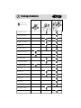
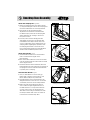
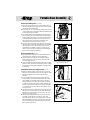
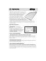
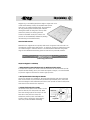
4-
4-
Kreg Jig
®
K3 Pocket Hole System
K3 Master System
INSTRUCTIONAL MANUAL
K3 Standard Pack
Item# K3MS
Item# K3SP
K3 Upgrade Kit
Products covered by one or
more of the following patents:
4,955,766
5,676,500
6,481,937
6,726,411
Other patents pending.
Item# K3UP
The Blue Mark of Quality.
Version 2005701
NK3022
1
Table of Contents
4-
Table of Contents
1
Warnings and Cautions
2
Package Contents
3
Parts Identification
4
Benchtop Base Assembly
5
Portable Base Assembly
6
Quickstart Guide To Building Your First Pocket Hole Joint
Getting To Know Your K3 System
Selecting The Correct Screw
Self-Tapping Screw FAQ’s
7-8
9-16
17-19
20
Face Frames
21-22
Leg and Rail
23-24
Mitered Joints
25-26
Angled Joints/Curves
27-28
Edgebanding
29
Edgejoining
30
Plugging A Pocket Hole
31
General FAQ’s
Warranty and Contact Information
32-33
34
4-
Warnings and Cautions
2
Thank you for your purchase! Kreg Tool Company is proud to
manufacture top quality tools and accessories that are surpassed only by
our commitment to customer service. If after reviewing this manual you
still have a question or concern that you would like addressed please
visit our website at www.kregtool.com, call 800-447-8638 or email
[email protected]. This manual covers the basics of
pocket hole joinery including the Kreg Jig® K3 Pocket Hole System. In
addition, a joinery guide located towards the back of the manual details the
basics for producing a variety of wood joints utilizing pocket hole joinery.
We offer various educational materials to help you get the most out
of your Pocket Hole tools. In addition to educational videos, we also offer
a plan CD which contains 15 Pocket Hole project plans in a PDF format that
can be printed from your home computer. Video titles include...
• The Pocket Hole Solution to Cabinetmaking
• The Pocket Hole Solution to Tables
• The Pocket Hole Solution to Building Your Own Router Table
• The Pocket Hole Solution to Home Improvements
Warnings and Cautions
CAUTION! : Handle drill bit carefully - Like any cutting tool, flutes
of drill bit are extremely sharp.
Never hold a pocket hole jig by hand while drilling holes. Always
secure jig and workpiece to an immovable object before drilling.
Always check drilling depth in scrap material before producing final
pocket holes and driving screws.
Make sure material is securely clamped into jig before drilling.
Always allow drill bit to reach full speed before plunging into the
workpiece.
3
Package Contents
K3 Upgrade Kit
- Indicates what is
included in package.
3/8” Step Drill Bit (KJD)
3”-#2 Square Driver Bit (D3)
6”-#2 Square Driver Bit (D6)
Allen Wrench - 1/8” (AW18)
Depth Collar (KJSC)
Premium Face Clamp (PFC)
Material Support Stop (KJSS)
Dust Collection Shroud (NK3005)
Portable Base (NK3036)
K3 Drill Guide Block (NK3003)
Benchtop Base (NK3035)
SPS-C1 Screws
SML-F125 Screws
SML-C125 Screws
SML-C150 Screws
SML-C2 Screws
SML-C250 Screws
Standard Pack Case (NK3031)
Master System Case (NK3023)
4-
K3 Standard Pack
K3 Master System
Parts Identification
4-
Benchtop
Base
K3 Drill Guide Block
Brass
Index Pin
Brass
Index Pin
Portable
Base
Depth Collar/Allen Wrench
3”-#2 Square
Driver Bit
3/8” Step Drill Bit
Dust
Collection
Shroud
Material
Support
Stop
6”-#2 Square Driver Bit
Premium
Face Clamp
Part Number
Description
KJD ................................. 3/8” Step Drill Bit
D3 ................................... 3”-#2 Square Driver Bit
D6 ................................... 6”-#2 Square Driver Bit
AW18 ............................. Allen Wrench - 1/8”
KJSC................................ Depth Collar
PFC ................................. Premium Face Clamp
KJSS ................................ Material Support Stop
NK3005 ......................... Dust Collection Shroud
NK3009 ......................... Brass Index Pin
NK3036 ......................... Portable Base
NK3003 ......................... Drill Guide Block
NK3035 ......................... Benchtop Base
NK3031.......................... Standard Pack Case
NK3023 ......................... Master System Case
Standard Pack Case
Master System Case
4
5
Benchtop Base Assembly
Attach the Clamping Pad (Fig. 5A&B)
1. Attach the Clamping Pad to the Clamp Follower
by simply threading the shaft of the Clamping Pad
into the threaded insert of the Clamp Follower.
2. The position of the Clamping Pad will be
adjusted for the thickness of the material to
be drilled. Proper position of the Clamping Pad
will be outlined in the “Getting to Know Your
K3 System” section.
3. You may notice that the Clamping Pad will
angle slightly upward once the Clamping Pad
is installed into the Clamp Follower. This is the
correct configuration of the Clamping Pad. The
Clamping Pad is angled slightly upward to assist
the clamping mechanism to insure the work
piece is seated tight against the Drill Guide Block
and flush with the Benchtop Base surface.
Attach the Index Pin (Fig. 5C)
1. Thread the Brass Index Pin into the threaded
insert contained in the upright of the
Benchtop Base.
2. Back off the Brass Index Pin so that the rounded
point of the Brass Index Pin is flush with the inside
of the upright surface.
3. The Brass Index Pin will be seated fully when the
Drill Guide Block has been inserted in the opening of
the upright and used to hold the Drill Guide Block
in position prior to clamping.
Store the Allen Wrench (Fig. 5D)
1. The 1/8” Allen Wrench is used to lock the
Depth Collar in position on the Kreg Jig® Drill
Bit for different depths of pocket holes.
2. The Allen Wrench may be stored either in the
designated location in the case or it can be held
conveniently in the rear of the Clamp Follower.
3. When using the Clamp Follower location be
sure to rotate the right-angled extension of
the Allen Wrench to a clock position between
9 o’clock and 3 o’clock. This will prevent the
Allen Wrench from being accidentally lost when
the Clamp Follower slides across the center rib
in the bottom of the Benchtop Base.
4-
Fig. 5A
Hex nut on threaded shaft.
Fig. 5B
Clamping Pad clamped against board.
Fig. 5C
Inserting the Brass Index Pin.
Fig. 5D
Storage for the Allen Wrench.
4-
Portable Base Assembly 6
Attach the Locking Tabs (Fig. 6A&B)
1. Align the center-hole of each of the Locking Tabs to
the corresponding mounting hole on the rear vertical
surface of the Portable Base.
2. Insert a #6 x 3/8” screw through center-hole of each
of the Locking Tabs and tighten while still allowing the
Locking Tabs to move freely.
3. The smaller pad of the Premium Face Clamp will be
held in position on the Portable Base by rotating the
Locking Tabs so that they cover the outside surface
of the Premium Face Clamp pad. Proper position of
the Premium Face Clamp will be outlined in the
“Getting to Know Your K3 System” section.
4. You may notice that there are raised ribs on the rear
outside surface of the K3 Portable Base surrounding
the openings used for wood chip ejection. These
raised ribs are provided so that any clamp may be
used to secure the K3 Portable Base and Drill Guide
Block to the material to be drilled.
Attach the Index Pin (Fig. 6C)
1. Thread the Brass Index Pin into the threaded insert
contained in the upright of the Portable Base.
2. Back off the Brass Index Pin so that the rounded
point of the Brass Index Pin is flush with the inside
of the upright surface.
3. The Brass Index Pin will be seated fully when the Drill
Guide has been inserted in the opening of the upright
and used to hold the Drill Guide Block in position prior
to clamping.
Assemble the Kreg Jig® Support/Stop (Fig. 6D)
1. Slide the center tongue of the Support/Stop Arm
between the outside extensions of the Support/Stop
Base and align the pivot hole through all three
surfaces.
2. Insert the Pivot Pin through one outside surface
of the Support/Stop Base and either tap into place
with a mallet or a hammer and a block of wood to
prevent marring the end of the Pivot Pin. Continue
to advance the Pivot Pin until it is fully seated in the
Support/Stop Base and Support/Stop Arm. Push the
1/4”-20 Hex Nut into the side of the Support/Stop
Arm hex recess.
3. Thread the Nylon Stop Bolt from either side through
the Support/Stop Arm into the Hex Nut. Which side
will depend on which side of the Kreg Jig® that the
Support/Stop will be used.
4. Thread the Knurled Nylon Lock Nut onto the Nylon
Stop Bolt on the side of the Support/Stop Arm
opposite the Hex Nut. It may be necessary to thread
the Knurled Nylon Lock Nut onto the Nylon Stop Bolt
prior to threading the Nylon Stop Bolt into the Hex
Nut in some applications.
Fig. 6A
Locking Tabs on Portable Base.
Fig. 6B
Locking Tabs holding the Premium
Face Clamp in position.
Fig. 6C
How to insert the Brass Index Pin.
Hex Recess
Knurled
Nylon
Lock
Nut
Fig. 6D
Nylon Bolt
Arm
Hex Nut
Base
Pivot Pin
Support/Stop assembly diagram
7
Quick-Start Guide...
4-
To Building Your First Pocket Hole Joint
Ready to jump in and start building? Here is a quick-start guide to
creating your first pocket hole joint.
Before you start... a few Pocket Hole Joinery Facts
• You only need to drill a pocket hole into ONE of the workpieces to be
joined. No pre-drilling of the second workpiece is required with the use
of self-tapping screws.
• The step drill bit forms both a pocket hole for the screw head and a
guide hole for the screw shank in one motion.
• Gluing the joint is optional.
• Simply clamp the two workpieces to be joined to hold flush alignment
and drive the screw.
1.
STEP 1 - Set the drilling depth.
(this example assumes using 3/4” thick material)
(CAUTION! Drill bit flutes are extremely sharp! Handle with care.)
The first step in creating a pocket hole joint is to set the drilling depth of
your drill bit. Drilling depth is adjusted by changing the location of the depth collar
on the shank of the drill bit. For joining 3/4” thick material, place the depth collar
onto the shank of the drill bit. Use a tape measure to position the depth collar
3-9/16” from the SHOULDER of the drill bit. Tighten the depth collar in this position with the Allen Wrench provided.
Fig. 7A
Shoulder of Drill Bit
3-9/16”
TIP
Setting the depth collar
closer to the SHOULDER of
the drill bit will result in less
screw travel into the second
workpiece, moving the depth
collar further from the
SHOULDER of the drill bit will
result in more screw travel.
Deeper Hole
Depth Collar
Shallower Hole
Fig. 7B
Quick-Start Guide Cont. 8
4-
2.
STEP 2 - Prepare wood and
drill the pocket holes.
Fig. 8A
Prepare your wood by squaring the pieces to be joined
on all edges. Place the drill bit into your drill and tighten
securely. Place one workpiece to be joined onto the base
of the Kreg Jig® K3 as shown in Fig. 8A. Adjust the
clamping pressure of the clamp by turning the clamping
pad to firmly hold the workpiece into the jig. Next,
place the first 1-1/2” of the drill bit into any one of the
three drill guides making sure that the tip does not come
in contact with the workpiece. Bring the drill bit up to full
speed and slowly plunge the drill bit into the drill guide
until the depth collar reaches the top of the guide as
shown in Fig. 8B. Remove drill bit and drill the second hole
in an adjacent drill guide. Once drilling is complete,
unclamp and remove workpiece from jig, gently tapping
the workpiece to remove any remaining wood chips from
the holes you have just created.
3.
Fig. 8B
STEP 3 - Drive screws to secure the joint.
At this time, choose the correct screw length for your application. If you are
joining 3/4” material to 3/4” material, a 1-1/4” length screw is suggested. Add glue
to the joint line if desired. If you are joining the two pieces in a flat plane, such as
a frame, position the large pad of the Kreg Premium Face Clamp over the joint line
and clamp with firm pressure to hold them perfectly flush as shown in figure 8C.
Fig. 8C
Joint Line
Face Side
Large Pad
Place the self-tapping screws down into the pocket hole and drive with a cordless drill until tight. Your joint should be tight, flush and extremely strong. If you
encounter any problems, consult our FAQ section that begins on page 32.
9
Getting to Know Your K3 System
4-
Choosing the Correct 2-Hole Spacing
Spacing pocket holes across the width of a workpiece is important in maximizing the
strength of a joint. When framing most woodworking projects, it is recommended
to place two pocket holes across the width of a rail to keep the workpiece from
twisting once it has been assembled. The patented three-drill guide fixed spacing of
the Kreg Jig® Drill Guide Block makes it extremely easy to place two pocket holes in
a workpiece without having to unclamp and move the workpiece to drill the second
hole. A real timesaver when working with a variety of wood widths. We recommend
using the drill guide spacings indicated below for each rail width. For very wide pieces
such as panels, we recommend placing a pocket hole every 6-8 inches across the
length of the panel. Use any of the three drill guides to form the pocket on panels.
Fig. 9A
Use B & C Spacing
On 1-1/4” to 1-3/4”
Material
Fig. 9B
Use A & B Spacing
On 1-3/4” to 2-3/4”
Material
Fig. 9C
Use A & C Spacing
On 2-3/4” to 3-3/4”
Material
4-
Getting to Know Your K3 System 10
Adjusting the Drill Guide Block (Fig. 10A)
Lines molded into the side of the Drill Guide Block are
labeled with fractional designations that represent
the thickness of the material that is being drilled.
For example if you are drilling a pocket hole in 3/4”
material the line beside the marking of 3/4 is aligned
to the top of either the Benchtop Base opening or
the Portable Base opening.
Moving the Exit Point of the Screw (Fig. 10B)
As the Drill Guide Block of the K3 Kreg Jig® is raised
vertically, the exit point of the screw projects out
further from the base of the jig. The key here is
that the 15 degree drilling angle remains constant.
The result is that as you move the upright to your
desired material thickness setting, the screw will
automatically be aligned to exit on the centerpoint
of the workpiece.
Fig. 10A
Drill Guide Block markings.
Fig. 10B
Constant
15 deg.
angle
Using the Drill Guide Block Separately (Fig. 10C)
There are times when it is not convenient to use
one of the bases specially designed for the Kreg Jig®
K3; or it is awkward to clamp the Drill Guide Block in
position. For these occasions the Drill Guide Block has
been specially designed to accept two SML head style
screws to hold the Drill Guide Block in position while
drilling the pocket hole.
(CAUTION! You must use the center drill guide
hole (“B”) when peforming this operation.)
As the Drill Guide Block is raised,
the exit point of the screw projects
further from the base of the jig.
Centerlines on the Drill Guide Block (Fig. 10D)
Markings on the top surface of the Drill Guide Block
designate the centerlines of the three drill guides.
These markings also align with corresponding
markings on the surface of the Benchtop Base.
To place a pocket hole in a specific location, mark a
board with a pencil in the desired location, then align
the pencil mark with the corresponding centerline
marking on the Drill Guide Block or Benchtop Base.
Drive screws into chip extraction
holes to hold jig in position.
Fig. 10C
Fig. 10D
Pencil mark aligned with centerline
of Drill Guide Block.
Getting to Know Your K3 System
Fig. 11A
3/4” thick board with the
centerline marked.
Fig. 11B
1/2”
For example if you want the screw to exit at a
position closer to the inside of your workpiece, simply
mark the desired exit location on the edge of your
board and choose the line on the base of the jig that
most closely corresponds, then adjust the Drill Guide
Block to the same fractional setting height. Once
the Drill Guide Block is secured at that height the
resulting pocket hole will guide a screw to exit at the
predetermined location regardless of the thickness
of material.
4-
1”
Markings on the Benchtop Base (Fig. 11A&B)
A series of markings have been added to the
Benchtop Base that mark the exit point of the
screw for a given Drill Guide Block setting. These
markings will allow you to “estimate” the exit point of
the screw without needing to know what the actual
thickness of your material may be. These markings
are similar to the lines on a ruler. The longest lines are
labeled as 1/2”, 1”, and 1-1/2” and the lines that fall
between these labeled locations represent the 1/4”
increments and 1/8” increments (shortest lines).
1-1/2”
11
Centerpoint aligned with 3/4” mark
on base of jig showing the exit point
of the screw in this setting.
Fig. 11C
Setting the Depth Collar - Benchtop Base (Fig. 11C)
Standard Depth Collar settings are molded into the
face of the Benchtop Base. These drill depths allow
for maximum screw penetration in the mating
workpiece when using the recommended screw
for the size material being joined. To use these
markings align the stepped shoulder of the drill
bit with the desired mark on the base. As the Depth
Collar is moved away from the stepped shoulder of
the Drill Bit the resulting pocket hole will be deeper.
Be careful not to set the Depth Collar so that the
drill bit will penetrate the jig itself.
When departing from the designated drill bit depth
settings for the given material thickness the pilot
point of the drill bit should be kept a height of
approximately 1/8” (the thickness of a nickel)
above the surface.
Depth
Collar
Shoulder
of drill bit
aligned to 1”
mark on base.
Set shoulder of drill bit to desired
setting and tighten depth collar.
Fig. 11D
Close-up showing shoulder of drill bit
aligned to 1” marking on base of jig.
4-
Getting to Know Your K3 System
About the Front Side Clamp (Fig. 12A&B)
The clamping mechanism of the Kreg Jig® K3
Benchtop Base has been designed in a way that
requires no adjustment for varying thicknesses
of material. However you will need to adjust for
the common thickness of the material to be drilled.
This is accomplished by adjusting the location of
the Clamping Pad relative to the Clamp Follower.
With the clamping mechanism fully engaged (handle
in full horizontal position) rotate the Clamping Pad
until it pushes the material to be drilled against the
Drill Guide Block. Relax the clamping mechanism by
lifting the handle and the rotate the Clamping Pad
2-full-turns toward the material. This will allow the
clamping mechanism to exert the proper amount
of pressure against the workpiece when the
clamping mechanism is fully engaged.
12
Fig. 12A
Front side clamp shown in
“unclamped” position
Fig. 12B
The internal springs of the Clamp Follower will
tighten or relax as the material thickness of your
workpieces vary. To apply additional pressure the
Clamping Pad is rotated toward the workpiece,
however you must be careful not to compress the
springs an excessive amount and cause the springs
to take a “set” in a compressed state.
Examples of the clamping action
Be certain to tighten the Lock Nut on the Clamping
Pad to prevent the Clamping Pad from accidentally
loosening as material is clamped and unclamped
during normal operation of the jig.
About Dust Collection (Fig. 12C)
One of the most unique features of the K3 Pocket
Hole System is the addition of a Dust Collection
Shroud. The Drill Guide Block has been designed
so that wood chips created during the drilling
operation are allowed to escape the drill guides,
thereby minimizing the friction of the wood chips
against the rotating drill bit. Openings in the rear of
the Benchtop Base align with the chip extraction
holes of the Drill Guide Block to provide a clear path
for the wood chips to escape the drill guide.
Fig. 12C
Dust Collection Shroud with standard
1-1/4” diameter connection.
13
Getting to Know Your K3 System
About Dust Collection Cont. (Fig. 13A&B)
When the pressure opposite the openings is
reduced to less than standard air pressure the
wood chips will flow more freely from the drill
guides. This reduction in pressure is achieved
when a shop vacuum or dust collector is
connected to the rear of the Benchtop Base.
The Dust Collection Shroud forms a complete seal
around the openings in the rear of the Benchtop
Base and channels the chips from the drill guides
to a hose connected to a vacuum source.
The tabs on opposite sides of the Dust Collection
Shroud simply “snap” into place in the recessed
areas on the rear of the Benchtop Base. To
remove the Dust Collection Shroud simply
“squeeze” the sides of the Shroud and pull away
from the Benchtop Base. The exit port of the
Dust Collection Shroud is sized to accept a
common 1-1/4” shop•vac® style hose end.
Adapters are available from your local
woodworking retailer to connect other common
shop vacuum sizes such as 2-1/2” and dust
collection systems.
Mounting the Benchtop Base for
Maximum Effectiveness (Fig. 13C&D)
Mounting the Kreg Jig® K3 Benchtop Base to a
piece of plywood is a good way to prepare it for
use in the shop and allow it to be easily removed
from your work area to hang on a wall or shelf. We
recommend cutting a 3/4” thick piece of plywood
to 12” x 24”. This will allow you to attach the
Support/Stop at a location that will properly
support large panels and also properly operate
the clamping mechanism. The Benchtop Base
may also be mounted directly to a workbench
but remember to locate the jig near the front of
the work surface to allow for proper operation of
the clamping mechanism.
shop•vac® is a registered trademark of the
Shop-Vac® Corporation Williamsport, PA.
4-
Fig. 13A
Dust Collection Shroud easily snaps
onto the back of the Benchtop Base.
Fig. 13B
Standard 1-1/4” connection and
direction of dust flow.
Fig. 13C
Attach Benchtop Base to 3/4”
plywood with 1-1/4” screws.
Fig. 13D
Benchtop Base attached to 3/4” x
12” x 24” wide piece of plywood.
4-
Getting to Know Your K3 System 14
Markings on the K3 Portable Base (Fig. 14A&B)
Horizontal lines on the face of each side of the
upright of the Portable Base are used to set the
Depth Collar position on the Drill Bit. These drill
depths allow for maximum screw penetration in the
mating workpiece when using the recommended
screw for the size material being joined. To use these
markings the stepped shoulder of the Drill Bit is
aligned with the mark by sighting across the surface
of Drill Guide Block. Be careful not to set the Depth
Collar so that the Drill Bit will penetrate the jig itself.
When departing from the designated drill bit depth
settings for the given material thickness the pilot
point of the Drill Bit should be kept a height of
approximately 1/8” above the projected surface
of the Portable Base.
About the Premium Face Clamp (Fig. 14C&D)
The preferred clamping mechanism for the Portable
Base is the Premium Face Clamp. The Premium
Face Clamp is attached to the Portable Base by
rotating the Locking Tabs to locate the smaller pad
of the Premium face Clamp. The smaller pad is
placed within the recess on the back of the Portable
Base and the Locking Tabs are rotated to capture
the smaller clamp pad but still allow freedom of
movement of the Premium Face Clamp. After drilling
the pocket holes in the work pieces, the Locking Tabs
may be rotated to remove the Premium Face Clamp
so it may be used for assembly. A network of ribs sit
above the rear surface of the Portable Base so that
virtually any type of C-clamp may be used to hold
the Portable Base to the workpiece being drilled. The
K3 Portable Base provides a convenient way to drill
pocket holes in large panels or cumbersome work
pieces by simply locating the step of the Portable
base against the edge of the workpiece and
clamping in position.
Fig. 14A
Set the drill guide block to the
proper position prior to checking drill
bit depth collar setting.
Fig. 14B
Sight across Portable Base and Drill
Guide Block to set drilling depth.
Fig. 14C
Locking tabs capture small pad of
clamp on backside of Portable Base.
Fig. 14D
Premium Face Clamp in use on edge
of large panel.
15
Getting to Know Your K3 System
Adjusting the Premium Face Clamp (Fig. 15A)
Turn the adjustment screw of the Premium Face
Clamp in the counter-clockwise direction for
thicker materials and clockwise direction for
thinner materials. Clamping pressure is also
adjusted using the same adjustment screw; after
sizing the clamp opening for the thickness of
material, a half-turn of the adjustment screw
in the clockwise direction will provide sufficient
clamping pressure to hold the jig in place during
drilling. To increase clamping pressure turn the
adjustment screw clockwise; likewise to decrease
clamping pressure turn the adjustment screw
counter-clockwise.
Portable Base Wood Chip Extraction (Fig. 15B)
There are openings in the rear surface of the
Portable Base that align with the chip extraction
holes in the Drill Guide Block to allow a free path
for wood chips to exit the Drill Guide Block. By
allowing chips to escape less friction will occur
with the rotating drill bit thereby easing the drilling
stroke and extending drill bit life.
4-
Fig. 15A
Adjustment screw on the Premium
Face Clamp.
Fig. 15B
Arrow shows openings for the chip
extraction holes.
Fig. 15C
Temporary Mounting Portable Base (Fig. 15C)
The bottom of the Portable Base contains three
holes that allow it to be temporarily attached to
a workbench for drilling pocket holes in a vertical
orientation, similar to the Benchtop Base.
The function of the Portable Base in this setting
is virtually the same. The Drill Guide Block is set
for the thickness of material to be drilled and the
Depth Collar is set to the same corresponding
thickness. Although the Premium Face Clamp is
recommended for this operation, another type of
C-clamp may be used.
Screwing the Portable Base
down for vertical use.
Fig. 15D
Motion of Drill Block Guide sliding
down into the Portable Base.
Getting to Know Your K3 System
4-
Material Support/Stop (Fig. 16A-D)
The Material Support/Stop is a dual function feature
that both “Supports” large panels to keep them
perpendicular to the base of the jig, and “Stops”
workpieces in a desired position to easily repeat a
2-hole spacing across a rail.
If you intend to use the Support/Stop mainly as
a support, we recommend that you locate it 8-10”
from the base of the jig to provide proper
support across the full width of a panel. Add
multiple Support/Stops to your work surface to
gain more placement versatility (Item# KJSS). Screw
holes are provided to screw mount the Material
Support/Stop to the work surface.
The Material Support/Stop is also designed to
function as a position stop. The end of the Nylon
Stop Bolt is positioned to rest against the workpiece
to “center” the workpiece across the predetermined
2-hole spacing. By locking the Nylon Stop Bolt in
position several pieces of the same width may be
located and drilled quickly to minimize the time
involved in measuring the pocket hole location for
each workpiece. When the stop position is no longer
being used the Material Support/Stop Arm may be
pivoted out of the way to drill panels or large face
frame components. We recommend that you locate
the Material Support/Stop approximately 1/8” to
3/4” from the base of the jig for optimum
performance as a Stop.
You may notice that a notch in the bottom of the
Support/Stop Base is sized to span the profile of
Kreg Mini Trak. A special “T”-nut and #10-32 Machine
Screw are included with the Material Support/Stop
hardware pack for mounting to the Kreg Mini Trak.
By adding a length of Kreg Mini Trak to either side of
the K3 Benchtop Base an adjustable Support/Stop
system may be created to allow the drilling of several
pocket holes across the width of large panels at
repeatable locations.
The Material Support/Stop may also be used with
the K3 Portable Base as a Stop. Mount the Material
Support/Stop adjacent to the Portable Base in a
similar fashion as with the Benchtop Base.
16
Fig. 16A
Material Support/Stop shown in
“Stop” position.
Fig. 16B
1” tall Material Support/Stop shown
in “Support” position.
Fig. 16C
Material Support/Stop helping to
balance a panel.
Fig. 16D
Material Support/Stop positioning
workpiece for proper placement.
17
Selecting the Correct Screw
4-
Selecting the Correct Screw for Your Application
Selecting the correct screw for your application is a function of three variables.
1. Jig setting - Set jig to the same setting as your wood thickness (ie. 3/4”
setting for 3/4” thick wood.
2. Drill bit depth collar setting - Set your drill bit to the standard setting
using the base of the jig or the chart at the bottom of page 18.
3. Screw length - Use the chart below to select the correct screw length.
The chart below helps to select the correct screw type when joining like thicknesses of
wood (ie. 3/4” to 3/4” material) in both a frame and right angle application. This chart
assumes that you are using the setting of the jig that corresponds to the material
thickness you are drilling, and that you are using the standard drill bit depth collar
settings posted at the bottom right of page 18. These are simply standard guidelines
for screw penetration... we always recommend that you test your desired joint in scrap
material before drilling and assembling final pocket holes.
Joining 7/8” to 7/8” material
1-1/2” recommended screw length
7/8” Material
7/8” Material
3/4” Material
3/4” Material
Joining 3/4” to 3/4” material
1-1/4” recommended screw length
5/8” Material
We do not recommend
frame joinery of
1/2” to 1/2” material.
Joining 5/8” to 5/8” material
1” or 1-1/4” recommended screw length
5/8” Material
1/2” Material
Joining 1/2” to 1/2” material
1” recommended screw length
Selecting the Correct Screw 18
1-1/8” Material
1-3/8” Material
1-1/4” Material
1-1/4” Material
Joining 1-3/8” to 1-3/8” material
2” recommended screw length
1-1/2” Material
1-1/2” Material
Joining 1-1/2” to 1-1/2” material
2-1/2” recommended screw length
Joining 1-1/4” to 1-1/4” material
2” recommended screw length
1-1/8” Material
Joining 1-1/8” to 1-1/8” material
1-1/2” recommended screw length
1” Material
1” Material
Joining 1” to 1” material
1-1/2” recommended screw length
1-3/8” Material
4-
Standard Depth Collar Settings
To get the amount of screw penetration shown
in the charts, use the standard depth collar settings below as measured from the shoulder of
the drill bit to the depth collar. These distances
can also be referenced on the base of both the
Benchtop and Portable Base.
Jig Setting
1/2”
5/8”
3/4”
7/8”
1”
1-1/8”
1-1/4”
1-3/8”
1-1/2”
Depth collar distance from
shoulder of drill bit
3-1/4”
3-7/16”
3-9/16”
3-11/16”
3-7/8”
4-3/16”
4-1/8”
4-5/16”
4-1/8”
19
Selecting the Correct Screw
4-
Kreg self-tapping screws are specially designed for pocket hole joinery. They feature a
self-tapping auger point that eliminates pre-drilling and a large round head that seats flush
in the bottom of the pocket hole. All of our screws utilize a #2 square drive recess. The
deep recess of the square drive provides positive driver engagement to reduce cam-out.
Like every Kreg product, our screws are manufactured from the highest quality materials.
To manufacture a virtually unbreakable screw, industrial quality steel is first case-hardened
and then coated with a dri-lube finish which reduces driving torque and gives them their
bronze appearance. Many of our screw types are available in a weather resistant coating
that is approximately 10 times more corrosion resistant than a standard zinc plated screw.
Choosing the right screw...
We offer three thread types, two head styles and five different lengths to handle nearly
all pocket hole applications. The characteristics for choosing the screw for your project are
detailed below.
Thread Types
A fine-thread screw is used any time you’re driving the screw
into a hardwood (i.e., oak, maple, walnut, cherry, hickory, etc.)
The coarse-thread screw has a larger thread diameter and
provides greater holding power when driving a screw into soft
material such as plywood, particle board, MDF, melamine, and
pine. We also offer a Hi-Lo thread type which consists of two
separate threads, one higher than the other that serves as a
general purpose screw in medium hardwoods like poplar. The
Hi-Lo screw is only offered in the 1-1/4” length.
Head Styles
The washer head (SML) screw is our most popular head style as
it provides the largest amount of surface area to seat firmly
in the bottom of the pocket. Available in both fine or coarse
thread, this head style is highly recommended if the material
the pocket is drilled into is soft such as plywood or pine. The
large washer head assures that the screw is not overdriven in
the bottom of the pocket.
Fine
Coarse
Hi-Lo
Maxi-Loc
Head
Pan
Head
The second available head style is the pan head (SPS). The pan
head is slightly smaller in both head and shank diameter than
the washer head screw and is a good alternative to the washer head screw if both mating
workpieces are made of extremely hard woods. The pan head style is also of benefit in the
1” length as it allows one to join 1/2” and 5/8” stock and easily seat the screw head below
flush.
Screw Length
There are five thread lengths most commonly used in pocket hole joinery; 1”, 1-1/4”,
1-1/2”, 2”, and 2-1/2”. Choosing the correct screw length depends on the setting of your
jig and the depth at which you drill the pocket hole. Both of these standard setting can be
viewed on the previous pages.
4-
Self-Tapping Screw FAQs 20
What screw type (thread) should I use in hardwoods, softwoods?
It is recommended to use a fine thread screw in hardwoods such as oak, maple,
walnut, cherry, hickory, etc. Use a coarse thread screw in softer materials such
as pine, plywood, melamine, MDF and particle board.
What screw length should I be using?
Our general recommendations for joining like material thicknesses are posted on the
previous pages. We always recommend that you test the amount of screw penetration
into your second workpiece with a scrap piece of material that is the same thickness as
the stock you will be actually joining. Drill a pocket hole, run a screw into the scrap piece
in air, then hold the scrap piece up to the second workpiece to visually verify screw
penetration depth. Adjust for deeper or shallower penetration by changing the setting
of the jig, moving the depth collar or using a different screw length.
My wood is splitting when driving the self-tapping screws.
The first thing to check is the hardness of the material you’re working with and
the thread pitch of the screw. We always recommend using a fine thread screw
in hardwoods such as oak, maple, hickory, cherry, walnut and a coarse thread
screw in plywood, particle board, MDF, melamine, pine, etc. If you are already
using a fine thread screw in hardwoods and are still having trouble, you may want
to try our SPS-F125 or SPS-F150 screw. These screws have a slightly smaller
shank size than the washer head screws (SML-F###). Lastly, whenever you
encounter problems with materials splitting it is advised to slow down the speed
of the driver.
Heads are breaking off when driving the screws.
Not all self-tapping pocket hole screws are created equal. Our screws are
designed with a larger head than most common self-tapping screws making
them much more likely to strip-out before the head of the screw breaks off. If
you are having problems with the head breaking off in a box of KREG Pocket
Hole Screws please let us know so we may make it right with you.
What screw should I use in 1/2” plywood?
This is normally a drawer box assembly question. We recommend using the
SPS-C1 screw. This is a pan head coarse thread screw. The pan head is smaller
than the washer head screw and more easily seats below the surface of the 1/2”
material. The coarse thread provides maximum holding power in plywood.
21
Face Frames
Frames are common to many types of woodworking projects from
cabinets to entertainment centers, doors and more.
The thread that ties all of these applications together
is that the workpieces are assembled in a flat plane.
Frames are commonly assembled from material as
thin as 5/8” up to 2” thick. For cabinets, 3/4” thick
material is the standard. The goal is to always use
the setting of the Kreg Jig® that will allow you to
place a pocket hole so that the screw will exit the
mid-point of your material (ie. for 3/4” thick stock,
you will want the screw to exit at 3/8” by using the
3/4” setting of the jig)
Face Frame Components
A. Rail – Horizontal members of a face
frame. Pocket holes are always placed into
the rail so that the screw will be driven into
the stile across the grain.
B. Stile –Vertical members of a face frame.
Stiles capture the rail, that is, they run all the
way from top to bottom and the rails fit in
between.
Standard Face Frame Dimensions
A typical face frame measures 31-1/2” tall by approximately 24” wide
when assembled. You can just as easily build a face frame to custom
dimensions such as 31-1/2” tall by 48” wide with pocket hole joinery. Rail
and stile widths typically range from 1-1/2” to 2-1/2” wide.
Steps to Building a Face Frame
1. Plane wood to thickness, rip to width and cut square to length.
Planing your wood to the same thickness assures that you will produce
flush frames without a great deal of sanding once assembled. Cutting
your materials accurately will greatly affect overall squareness as a
pocket hole joint will pull the workpieces into alignment with the cut
edge. (An untrue cut will be pulled into untrue alignment!)
4-
4-
Face Frames 22
2. Layout and mark your workpieces.
We recommend that you layout your cut workpieces on a workbench and mark
each piece on the side that will receive the pocket holes. Measure corner to
corner for square.
3. Drill pocket holes in both ends of rails.
Prepare the jig you will be using to center the screw
in the material thickness being joined and set your
depth collar accordingly (see jig instructions). You
will want to place at least two pocket holes across
the backside of the rail to make sure that it will not
twist once assembled.
4. Position rails into alignment with
reference marks on stile.
After the pocket holes have been drilled
into the rails, place the workpieces into
final alignment on a workbench or assembly
grid. If your face frame will have a
drawer bank, a good way to reference the
size of the opening is to cut a story stick to
size that will allow you to consistently and
accurately place the intermediate rail.
Joint Line
Face Side
Large Pad
5. Clamp over joint line and drive screws.
No pre-drilling is required of the stile as long as you are using a self-tapping
wood screw. Add glue to the joint line at this time if desired. Place the KREG
Face Clamp or Bench Klamp on the joint line to hold the rail and stile perfectly
flush as the screws are driven.
Occasionally in very hard or dry material you may split the very top or bottom
of a rail when driving a screw. To combat this try cheating the pocket hole on
the rail so they are further from the edge of the stile. Another tip is to use a #6
shank size screw such as the SPS-F125 as opposed to the standard SML-F125
which is a #7. Another option is to use only one pocket hole per rail end if
necessary.
23
Leg and Rail
The Leg and Rail joint is a standard with table
and chair assembly. Design options include
either a set-back or flush rail. Use corner
braces or a gusset to stiffen the joint. Pocket
holes can also be drilled upwards into the rail to
attach the table top at a later time.
Leg and Rail Components
A. Leg – The main vertical support that extends all the way to the floor.
Can be turned, square, rectangular or tapered.
B. Rail – Horizontal members that are screwed into the Leg.
C. Gusset or corner brace – Squaring / support blocks that reinforce the joint.
Standard Leg and Rail Dimensions
Tables and chairs come in various sizes but all incorporate a Leg and Rail
connection. Legs can be purchased pre-turned, as furniture squares or
laminated from thinner pieces of stock. Typical finished leg sizes range
from 1-1/2” to 6” square. Rail widths will vary according to the size of the
leg and overall length of the table or chair. 3/4” thick rails are very common
in coffee tables, end tables and sofa tables while thicker rails may be found
on dining tables.
Steps to Building a Leg and Rail Joint
1. Buy or prepare legs for assembly.
One of the most economical ways to construct legs for coffee and end
tables is by simply laminating two pieces of 3/4” stock together. Plane
your material to the same thickness, rip square, clamp and glue overnight.
Once dried, trim and cut to final length.
2. Drill pocket holes into end of rail.
Normally two or three pocket holes across a 3” rail is sufficient. If
you are planning on attaching the table or chair top through the rail
it is recommended to drill the pocket holes upward into the rail at
this time before final assembly to the legs.
4-
4-
Leg and Rail 24
Set-back Rail A rail that is set-back from the edge of the leg to highlight a reveal is a very
common way to dress up a table or chair and give the design depth and sophistication.
This set-back is very easy to achieve with pocket hole joinery.
Cut a piece of material to the thickness of
your desired set-back (1/4” plywood works
well). Secure the leg to a workbench with a
clamp. Butt the 1/4” plywood, or desired
material, up against the leg at the location to
be joined. Set the rail onto the plywood so it
is raised off the workbench, clamp if desired
and drive the screws.
Flush Rail This is the simplest form of a leg and rail connection where the rail is attached
perfectly flush to the edge of the leg.
Secure the leg to a flat workbench with a
clamp. Butt the rail up against the leg at the
location to be joined making sure the top
edge of the rail is flush with the top of the
leg. Clamp the rail to the workbench if
desired and drive the screws.
Gusset Supports A great way to add strength and square up a
corner.
On a typical table with a 2” square leg and a
1/4” set-back rail you will want to first create
6-8”
a right triangle gusset with a 6-8” hypotenuse.
Hypotenuse
Next cut a 1” by 1” square out of
the corner. Take the finished gusset and
place a pocket hole perpendicular to the
short legs of the right triangle so that the
screw will be driven directly into the rails
(make sure to check the amount of screw
penetration in a scrap workpiece before final assembly). You can also place a
pocket hole into the corner of the gusset with the Mini Kreg Jig® to further tie it
into the leg.
25
Mitered Joints
4-
This section relates to mitered joints that are
assembled in a flat plane such as a picture frame.
This is probably one of the most challenging
types of joints to produce with pocket hole
joinery. Understanding how the orientation of
the pocket hole and the width of the stock being
joined varies will allow you to join frames more
easily.
Miter Components
A. Miter toe – The outside point of a
mitered workpiece.
B. Miter heel – The inside corner of a
mitered workpiece.
C. Rabbet – This is typically a 3/8”
wide by 1/2” deep L-shaped groove set
into the edge of the frame that allows
the backing material to be inserted.
Standard Miter Dimensions
A miter cut refers to anything other than a 90 degree cut. Two 45 degree
miter cuts when assembled create a 90 degree joint, while two 30 degree
angles will produce a 60 degree joint. To calculate the angles needed to
make a hexagon, octagon, etc. simply take 360 degrees and divide it by the
number of sides multiplied by two (ie. For an octagon take 360 / (8 * 2) =
22.5 degrees
Triangle
Square
Pentagon
Hexagon
60 degrees
45 degrees
36 degrees
30 degrees
Heptagon
Octagon
Nonagon
Decagon
25.7 degrees
22.5 degrees
20 degrees
18 degrees
Frames are typically made from 3/4” thick stock. Material width of frame
members can range from 1-1/2” wide to 5” wide and beyond. One thing to
keep in mind with pocket hole joinery is that the wider the frame members,
the easier they are to join. Many frames also incorporate a standard 3/8”
wide by 1/2” deep rabbet into the inside edge of the frame that serves to
allow the glass, picture and backing material to be secured.
4-
Mitered Joints 26
Steps to Building a Miter joint
1. Plane material to uniform thickness, rip to width and rout rabbet if desired.
2. Cut desired miter on workpiece and position to drill pocket holes.
There are a few different ways to join mitered pieces with pocket hole
joinery. This example below focuses on joining two 45 degree mitered
pieces by placing two pocket holes across the workpiece perpendicular
to the edge of the miter as shown in the image at right. The workpieces
are 3” wide with a 3/8” rabbet along the inside edge.
a. Position one workpiece so that the edge
of the miter rests entirely on the base of
the jig and the drill guides will not interfere
with the edge of the board or the rabbet as
shown at right. On this 3” wide piece, use
the A-C setting of the Kreg Jig® K3 or a
1-1/2” center to center pocket hole spacing.
b. If your workpiece is less than 2” in
width, you may need to raise the heel of
the miter off of the base of the jig slightly in
order to get the entire impression of the
pocket hole on the backside of the
workpiece. Adjust drilling depth and screw
length accordingly in this situation.
3. Clamp and drive screws.
You can use many different styles of clamps
to hold the workpieces flush while the
screws are driven. If you will be assembling
a number of miter joints you may want to
produce an assembly fixture to help hold the
toes of the miters in perfect alignment. The
fixture consists of a piece of plywood that
has two hardwood pieces attached to it to
form a perfect 90 degree angle. You can add
an overhead clamp to this fixture to produce
consistent clamping results.
Base
Base
Heel raised off
base of jig
27
Angled Joints/Curves
Angles and curves are a great application
for pocket hole joinery. With other
methods of joinery an angled joint must
by held in alignment for a substantial
amount of time with bar clamps. Uneven
pressure along the joint line can result in
bowing, gaps or misalignment. The
pocket hole joint solves this by putting
constant pressure along the joint line in
the form of screws that pull the two flat
surfaces tightly together.
4-
Two 22-1/2 deg. pieces.
A typical 45 degree angle such as what
you might find on an angled cabinet face
frame front is traditionally made by joining
One 90 and one 45 degree before trimming.
two 22-1/2 degree pieces. With pocket
hole joinery this joint is constructed by
cutting the entire 45 degrees on one
workpiece and leaving the other piece as
a 90 degree. These two workpieces are
then aligned flush on their inside edges
which leaves an overhang on the front
Finished 45 degree angle.
side which can be taken off with a jointer,
sander or hand plane once assembled (if
you don’t have a jointer, you can tip your table saw blade to 45 degrees, cut it close
and then finish with a belt sander).
The result of this assembly method is that once the overhang is taken off the joint line
is in effect “shifted” around the corner and hidden from view. The resulting solid wood
corner is more resistant to wear and abuse because the mitered edges are no longer
exposed on the edge. This same concept can be adapted to any angled joint application.
Do not use plywood for angled stile as the ply will show after trimming the overhang.
Angle Components
A. Angled Stile – The workpiece that contains the entire desired angle cut on one
edge.
B. 90 degree Stile – The second workpiece to be joined cut at a 90 degree angle on
both edges.
C. Assembly Jig – A homemade fixture you will want to build that will help hold the
inside edges of the two stiles aligned while the screws are being driven.
4-
Angled Joints/Curves 28
Steps to Building an Angled Joint
1. Plane stiles to same thickness, rip to width and cut square to length.
Place desired angle on inside edge of one stile.
2. Build an assembly jig from scrap stock.
We recommend that you first
cut a plywood base 8” by
12”. Next laminate two 3/4”
x 4” x 12” hardwood pieces
together with glue and then
cut the block on an angle that
will complement your desired
assembly angle. Mount this
angled piece to the plywood.
Lastly, take your workpieces
to be assembled, align them
on their inside edges and
measure the overhang that
occurs. Make a shim the same height as the overhang measurement and attach this to
the plywood base so that the edge butts up with the angled piece.
3. Drill pocket holes into the edge of the 90 degree stile.
Prepare the pocket hole jig you will be using to center the screw in the material
thickness being joined and set your depth collar accordingly (see jig instructions).
We recommend that you place pocket holes every 6-8 inches along the length of
the stile. Test the drill depth and screw penetration in scrap workpieces that are the
same thickness as your actual stock before final assembly. If the screw tip protrudes
too far into the second workpiece you can simply set the depth collar closer to the
step of the drill bit to create a shallower hole.
4. Position stiles and drive screws.
Apply glue at this time if desired. Alternate from one end the the other as you slide the
stiles across the assembly jig you have created. Press down onto the angled stile as you
assemble to create a uniform overhang.
5. Remove overhang from the front edge.
Remove the overhang from the front edge of the workpieces with a jointer, sander or
hand plane once assembled (if you don’t have a jointer, you can tip our table saw blade
to 45 degrees, cut it close and then finish with a belt sander).
29
Edgebanding
4-
Edgebanding, or placing a solid wood edge piece onto
plywood or melamine to hide the unfinished edge is a
great application for pocket hole joinery. Typically
used for countertops, tabletops and shelves. In
the past this process would be completed by
either brad nailing the solid wood onto the
plywood which would require time consuming
filling and sanding of the brad holes, or simply gluing
the solid wood onto the plywood and holding it in place
overnight with bar clamps. Using pocket holes placed into the
underside of the plywood to secure the hardwood creates an extremely fast and
strong joint resulting from the large amount of clamping pressure exerted by the
self-tapping screws.
Edgebanding Components
A. Edgebanding — Typically a piece
appoximately 1” x 1-1/2”solid wood cut to
correspond with the dimensions of the
countertop/ shelf. Often has a routed profile
to soften the edges and add visual appeal.
B. Plywood / Melamine -- (3/4”thick)
Steps to assemble Edgebanding
1. Rip edgebanding to size. Rout desired profile. Cut to length.
Rip the solid wood piece to size making sure that all edges are square and true. Rout
profile onto the stock at this time. Cut to length and dri-fit to plywood or melamine
before assembling.
2. Drill pocket holes into plywood.
We recommend that you place pocket holes every 6-8 inches along the length of the
plywood for adequate holding power.
3. Drive screws to assemble edgebanding.
Apply glue at this time before assembly. A great way to assemble edgebanding for a
perfectly flush fit is to firmly clamp the solid wood piece down to a flat surface using
the Kreg Bench Klamp. Then slide the ply material into position and drive a fine thread
self-tapping screw. Make sure that you test the amount of screw travel in scrap pieces
before final assembly.
Edgejoining 30
4-
Edgejoining, or assembling workpieces edge to edge such as for
a solid wood tabletop is easily accomplished with pocket
hole joinery. In traditional edgejoining, the workpieces
are only glued together and then pipe clamped
overnight to allow for the glue to set-up. With
pocket hole joinery one simply glues and
screws to assemble one layer at a time. This
process can be immediately followed by sanding
and trimming to size without delay.
Standard Dimensions
Materials to be edgejoined are typically solid wood. The general rule of thumb is to
not edgejoin a board that is wider than 5” to avoid any cupping or bowing that could
occur with changes in moisture levels. It is recommended to alternate the growth
rings of the individual boards being joined to head off any potential problems.
(Alternating grain direction)
Steps to Edgejoin a Tabletop
1. Plane wood to same thickness. Rip to width and joint edges.
It is important to plane your wood to the same thickness to assure a flush top that
requires minimal sanding. Once your boards are ripped to length, it is recommended
to joint the edges of the board to create a tight joint line.
2. Drill pocket holes into edge of boards.
Layout your boards on a workbench. Alternate grain direction and choose the best
face on each board. Layout pocket hole placement approximately every 6-8 inches
across the length of the board with pencil lines (note you will not have to drill pocket
holes into the first board in the sequence).
3. Clamp flush and drive screws.
On the first board, place a Face ClampTM on the
joint line directly over the pocket hole. Make
sure that the large pad of the clamp is on the
face side of the joint line to keep the
workpieces perfectly flush. Assemble one
screw at a time, moving the clamp directly
over each pocket hole while assembling.
Joint Line
Face Side
Large Pad
31
Plugging A Pocket Hole
4-
Normally pocket holes are placed on the backside or underside of a project where they
are hidden from view. From time to time however, you may find the need to place one
in a visible location. In this event, KREG manufactures solid wood pocket hole plugs that
can be glued in over the head of the screw and sanded flush to conceal the hole. These
plugs are available in a variety of wood species.
Anatomy of a Pocket Hole Plug
Plugs are cut at an angle so that they sit
perfectly flush on the top of the screw head
when fully inserted. A small amount of plug will
remain above flush and will need to be either
trimmed off with a hand saw or sanded.
Steps to Plug a Pocket Hole
1. Drill hole to adequate depth and drive screw to secure joint.
One of the most frequently asked questions we receive is why does the plug
not fully cover the pocket hole? Normally this is caused by not drilling the
pocket hole deep enough to allow the plug to fully close the hole. Our normal
suggestion is to set the depth collar on the drill bit approximately 1/8” further
from the step of the drill bit to insure that the screw head will be deep enough
into the pocket.
2. Glue and press into place.
Place a fair amount of glue into the bottom of
the pocket and then also around the perimeter
of the plug itself. Press into place and
wipe away excess glue. The Mini Kreg Jig®
contains a recess on its’ underside that can
be used to firmly seat the plug into place.
Pressing a plug into place.
3. Trim or sand off excess plug.
Once the glue has setup, plugs can be trimmed or sanded off. Softwoods such
as pine and basswood can often be made flush with an orbital sander while
hardwoods such as oak and maple will most likely require trimming with a flush
cut handsaw before final sanding. We have found that a laminate trimmer fitted
with a bull-nose bit and a 45 degree base also works well if you will be trimming
a number of plugs.
4-
General FAQ 32
Why do I need to use a 2,000+ rpm drill to make the pocket holes?
What brand do you recommend?
A drill that is rated at 2,000 RPM or above is considered a woodworking drill. RPM’s below that are normally seen in metal-working drills. The higher the RPM, the cleaner the
hole and the longer the drill bit lasts. A 1,500 RPM drill will do the trick, but you will see
slightly more wear on the bit over time. Most of the major tool manufacturers produce
a drill above 2,000 RPM.
Do I need to drill all the way through the edge of the workpiece?
No. We recommend setting the depth collar so that the tip of your drill bit rests approximately 1/8” from the base of the jig for 3/4” material. Why you ask? By not drilling all the way through the edge you won’t have to deal with the possibility of having
a burr that you will need to remove before joining your pieces. The self-tapping tip of
the pocket hole screw will easily drill through the last 1/8” of an inch and drill its own
hole into the second workpiece, drawing the pieces tight without having to pre-drill.
Do I need to drill a pilot hole into the second workpiece?
No. The self-tapping tip of the pocket hole screw accomplishes this task for you. Even
in very hard woods like hickory and maple no pre-drilling is required which saves an immense amount of assembly time.
Can I use pocket holes in melamine and MDF?
Yes. They are usually a little more finicky than simple hardwoods so here are a few
suggestions that we find helpful…
1. Make sure you’re using a sharp drill bit.
2. SLOW DOWN! Use a slower feed rate while both drilling the pocket hole and driving
the screws.
3. Set the clutch setting on your driver to a light setting to avoid overdriving the screw.
4. Use a coarse thread, self-tapping screw with a washer head for maximum holding
power.
5. Try to place pocket holes at least an inch from the end of your workpiece.
(The workpiece may split if the screw is driven too close to the edge)
The pocket hole plugs sit well over flush when placed in the bottom of the
pocket hole. Is this normal? What is the best way to sand plugs flush?
Yes, this is normal. The depth that the plug seats into the bottom of the hole depends
on the depth of the hole that is drilled. We must make the plugs with a certain tolerance of plug length to allow for varying hole depths. As a general rule, the deeper you
drill the hole, the less plug you will need to sand off. There are a couple of different
ways to trim plugs. If you will be trimming very few plugs, a flush cut hand saw followed by a light sanding works very well. If you will be trimming many plugs we recommend using a laminate trimmer outfitted with a bull nose bit. Trim off the majority of
the plug, and then finish with a light sanding. See page 31 for more details.
33
General FAQ
4-
What is the recommended pocket hole spacing across a panel?
We suggest that you place pocket holes every 6-8 inches across the length of a workpiece for adequate strength. Feel free to place them closer or further apart as the
application warrants.
I am experiencing wood movement as I screw my joint together.
How can I eliminate this?
First and foremost, the use of our Face Clamps will eliminate most wood movement
while driving a screw. A good rule to use whenever attempting to assemble a pocket
hole joint is that the screw will tend to pull the workpieces away from the side the
pocket hole is placed on. Therefor, a simple solution is to always clamp a stop (clamp,
scrap workpiece, workbench) on the opposite side of the pocket holes. By doing this,
you will be able to consistently produce perfectly flush joints. Another trick that seems
to work well if you’re experiencing movement mainly caused by the lubricity of glue on
the joint line is to first dry fit your workpieces and drive one or two screws, then disassemble, apply glue to the workpieces and re-assemble.
I am afraid to use pocket holes because I am worried about wood expanding
and contracting with changes in the seasons. What do you recommend?
There are a couple of easy ways to compensate for this type of wood movement.
Let’s assume an example of attaching a rail or apron to a solid tabletop.
First, set your depth collar on the drill bit so you barely drill through the edge of
the rail or apron. This will create a larger pilot hole for the screw shank and
will create the effect of a “floating top”. Secondly, drive the screw into the
top until tightened, then back off 1/4 of a turn. This will allow for plenty of
expansion and contraction of the wood.
How can I get the longest life out of my drill bit?
We suggest following a few simple guidelines to get the longest life out of your drill bit.
1. Use a corded drill rated at 2,000 rpm or above (this is normally characterized as a
woodworking drill, a metal-working drill is usually rated under 1,500 rpm).
2. Place the bit into the drill guide before starting the drill.
3. Make sure the drill is up to full rpm before plunging it into the workpiece. Sharpen
the bit before it becomes so dull it breaks. In oak, this averages about every 2,500
pocket holes.
How many holes can I expect to drill before sharpening my drill bit?
You can expect to drill between 2,000 and 3,000 holes with your KJD drill bit when
working with oak material. Drill bit life directly correlates to material composition.
Can the Kreg drill bit be sharpened?
Yes, we have a factory sharpening service for KREG bits only. KREG drill bits have “Kreg”
stamped into the shank of the bit. We recommend sharpening the Kreg Jig® KJD bit
every 2,500 holes and the DKDB (machine) bit every 8,000 holes. Package the bit securely and send it along with a check to the address on the following page.
4-
Warranty & Contact Info 34
What type of warranty do the pocket hole jigs carry?
We are confident that you will enjoy your KREG products. The Kreg Jig® K3 Pocket Hole
System carries a lifetime warranty on the hardened steel drill guides when used with the
KREG KJD drill bit. All of our tools also carry a 30-day complete satisfaction guarantee.
If for any reason you are not completely satisfied within 30 days of purchase return
the product along with your proof of purchase to the location you purchased the
product from.
Are drill bits covered with a warranty?
No. Drill bits are not covered with any type of warranty. We are extremely
confident that with due care our drill bits will exceed your expectations. If you
are dissatisfied with the performance of your bit (ie. the bit broke on the 5th
drilled pocket hole) please review the guidelines for extending drill bit life and
contact us if you still have a concern and we will do our best to accommodate you.
Contact Information
Feel free to contact us with any questions, comments, concerns, or product
suggestions. Send via email [email protected] or mail to...
Kreg Tool Company
201 Campus Drive
Huxley, IA 50124
800-447-8638
515-597-2234
(fax) 515-597-2354
website: www.kregtool.com
email: [email protected]
4-
4-
Kreg Tool Company
201 Campus Drive
Huxley, IA 50124
Phone: 515.597.2234
Toll Free: 800.447.8638
Fax: 515.597.2354
www.kregtool.com