1
WINEGARD®
Chromstar 2000
AntennaMADE
Preamplifiers
IN U.S.A.
®
INSTRUCTIONS
Models AP-2870 & AP-2880 Dual Input, 82 Channel
Models AP-8275, AP-8700 & AP-8780, AP-8800, & HDP-269 82 Channel
Models AP-4700 & AP-4800 UHF Only
Models AP-3700 & AP-3800 VHF Only
Fig. 1
WARNING: TO PREVENT FIRE OR SHOCK HAZARD,
DO NOT EXPOSE POWER SUPPLY SECTION OF THIS
APPLIANCE TO RAIN OR MOISTURE.
NOTE
If FM interference is a problem in your area, it is recommended that you temporarily hook up the preamplifier near
the TV for ease of tuning the variable FM trap.
SUPPORT
PLATE
MAST
HEX NUT
U-BOLT
PREAMPLIFIER
300 OHM DOWNLEAD
HOUSING
Fig. 2
WEATHER
BOOTS
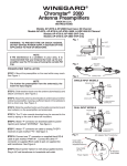
PREAMPLIFIER INSTALLATION
STEP 1. Mount the preamplifier on the mast within easy reach.
See Figure 1.
NOTE
The further the preamplifier from the antenna(s), the lower
the input signal.
Fig. 3
SINGLE INPUT MODELS
PREAMPLIFIER
MAST
CLAMP
STEP 2. Slide weather boots over the antenna downlead(s) and
attach connectors. See Figure 2.
ANT.
INPUT
75 OHM COAXIAL
DOWNLEAD
DUAL INPUT MODELS
PREAMPLIFIER
UHF
INPUT
STEP 6. Attach “F” connector on downlead cable from preamp
to Power Injector jack marked “ANT”. See figure 4.
STEP 8. Connect one “F” connector on supplied black RG-6
cable to jack on Power Injecter marked “PWR IN”. Connect
the other “F” connector on supplied RG-6 cable to jack on
supplied AC Adapter (Wall Transformer). See Figure 4.
STEP 9. Mount power injector to wall using supplied screws.
Plug in AC Adapter (Wall Transformer) into household wall
outlet.
MAST
CLAMP
VHF
INPUT
STEP 5. The 75 ohm coaxial downlead may be secured to the
mast with weatherproof tape or cable ties.
STEP 7. Attach “F” connector on cable from DTV, Digital
Converter box, Distribution Amplifier, or splitter system to jack
on Power Injecter marked TV. See figure 4.
TO POWER
SUPPLY
DRAIN LOOP
STEP 3. Attach the antenna downlead(s) to antenna(s) and other
end(s) to preamplifier, leaving a sufficient slack in the cable(s)
to form a drain loop. See Figure 3.
STEP 4. Slide the weather boots over the cable connector(s)
and boot collar(s) on the preamplifier and antenna(s).
CONNECTORS
TO POWER
SUPPLY
75 OHM COAXIAL
DOWNLEAD
DRAIN LOOP
Fig. 4
DOWNLEAD COAX CABLE FROM
PREAMP OR AMPLIFIED ANTENNA
POWER
INJECTOR
ANT.
AC ADAPTOR
(SUPPLIED)
TV
POWER IN
LED
6’ STANDARD
COAX CABLE
(SUPPLIED)
COAX CABLE TO
DIGITAL TV, DIGITAL
CONVERTER BOX,
DISTRIBUTION AMP,
OR SPLITTER (SYSTEM)
NOTE: This power supply is equipped with a Polyswitch. If there is a short between the preamp and the power supply, it will
shut the power supply off until the short is removed.
TIPS:
If splitting the signal to multiple TVs or combining with another signal source, it is strongly recommended that the power injector be
installed between the preamplifer and the splitter/combiner input. In this case, the cable connection from the “TV” jack of the power
injector goes to the splitter input or valid combiner input. Use splitters rated from 54-806 MHz or wider bandwidth (commonly 5-1000
MHz) for over-the-air television signal distribution.
Additional distribution/inline amplifiers must be installed FOLLOWING the TV output of the power injector, NOT on the downlead cable
line connecting to the ANTENNA port. Check TV picture quality, if the power injector LED is glowing when powered, and antenna
alignment prior to adding additional line amplifiers.
To maximize the operating life of the amplifier, install the power injector close to the TV receiver (if only one will be used with the
antenna) or the first signal splitter. A maximum preamp-to-power injector length of 150 feet RG-6 or 150 feet RG-59 is acceptable.
FM TRAP OPERATION (Not applicable to Models AP-4700, AP-4800, or HDP-269)
The preamplifier features two FM traps, one fixed and the other variable. The preamplifier is shipped with the fixed FM in the “FIXED
TRAP IN” position and the variable FM trap tuned out of the FM band (about 108 MHz). See Figure 5.
If FM reception is desired, move the FM trap switch to the “FIXED TRAP OUT” position.
FM interference is indicated by “herringbone” patterns appearing on any VHF channel (2 through 13). If this interference is present,
verify the FM trap is in the “FIXED TRAP IN” position. If interference is still present, turn the “VARIABLE FM TRAP” screw very slowly
while observing the TV channel with the greatest interference until the picture clears. See Figure 5.
The variable FM trap can also be used with the fixed FM trap in the “FIXED TRAP OUT” position. This allows you to receive FM and
tune out a specific FM station that is causing interference. This is performed the same as the proceeding paragraph except the FM trap
is in the out position.
SPECIFICATION : 14 Volts Nominal at 130 Milliamps Max.
APPLY LABEL AFTER TUNING
FIG. 5
APPLY LABEL
DUAL
INPUT
UHF
ANT.
FIXED TRAP OUT
+
VHF
ANT.
VARIABLE
FM TRAP
FIXED TRAP IN
TO
POWER
SUPPLY
NOTE: A label is supplied so you can enter the
installation date and record the frequency the variable trap is tuned to. Once tuning is complete, apply
the label to the bottom of the preamplifier to seal
openings. See figure 5. For models without traps,
apply the label to the bottom of the preamplifier to
seal openings.
WINEGARD COMPANY
BURLINGTON, IOWA
CONSUMER 90 DAY WARRANTY
The Winegard Company warrants this Winegard product against any defects in materials or workmanship within 90 (ninety) days from date of
purchase. No warranty claim will be honored unless at the time the claim is made, you present proof of purchase to an authorized Winegard dealer
(if unknown, please contact Winegard Company, 3000 Kirkwood Street, Burlington, IA 52601-2000, telephone 800-288-8094).
Winegard Company (at its option) will either repair or replace the defective product at no charge to you. This warranty covers parts, but does not
cover any costs incurred in removal, shipping or reinstallation of the product. The warranty does not extend to products which have been subjected
to misuse, improper installation, or to damage caused by wind, lightning, ice or other occurrences over which the manufacturer has no control.
The 90 Day Warranty is provided on the condition that the equipment is properly delivered with all handling and freight charges prepaid to your
Winegard dealer for return to our factory for repair or replacement. Winegard dealers will arrange for the replacement or repair and return to you
without charge the product which failed due to defective material or workmanship.
WINEGARD COMPANY WILL NOT ASSUME ANY LIABILITIES FOR ANY OTHER WARRANTIES, EXPRESS OR IMPLIED, MADE BY ANY
OTHER PERSON.
ALL OTHER WARRANTIES WHETHER EXPRESS, IMPLIED OR STATUTORY INCLUDING WARRANTIES OF FITNESS FOR A PARTICULAR
PURPOSE AND MERCHANTABILITY ARE LIMITED TO THE 90-DAY PERIOD OF THIS WARRANTY.
The foregoing shall be the sole and exclusive remedy of any person, whether in contract, tort or otherwise, and Winegard shall not be liable for
incidental or consequential damage or commerical loss, or from any other loss or damage except as set forth above.
Some states do not allow limitations on how long an implied warranty lasts, or the exclusion of limitation of incidental or consequential damages,
so the above limitations or exclusions may not apply to you.
This warranty gives you specific legal rights and you may also have other rights which vary from state to state.
Printed in U.S.A. • Winegard Company • 3000 Kirkwood Street • Burlington, IA 52601-2000 • © Winegard Company, 2006
Rev. 2/08
2451964 Rev. 1/12/09