1
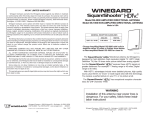
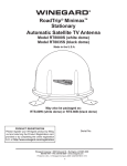
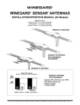
Automatic Multi-Satellite TV Antenna
Replacement Back-up and Feed Arm
Assembly with LNB and Coax Cable
Instruction Manual
for Model RP-SK95
For help, email [email protected] or call 1-800-788-4417
www.winegard.com/mobile
2452290
Raising the Antenna
1 Press and hold “POWER” for two seconds to turn on the interface
box. Wait until the interface box finishes “connecting to antenna.” The
TRAV’LER® antenna may enter the search routine after ten seconds.
Pay attention to the pinch points as the antenna raises!
2 Wait until the antenna has at least raised to a position in which the
LNB arm is parallel to the roof. Then, press “POWER” and “SELECT” at
the same time. The antenna should stop moving.
4 If there is not already a line marking the top of the stiffener plate, draw
a line on the stiffener plate to mark the top of the plate.
5 Using a ½″ wrench, loosen and remove the four bolts holding the
reflector bracket and stiffener plate to the skew housing. At the same
time, carefully remove the stiffener plate and LNB arm assembly. Set
aside the stiffener plate and four bolts; you will need these later.
Reflector bracket
Stiffener plate
3 Unplug the interface box.
Removing the LNB Assembly
Cable harness
Bolts holding reflector bracket and
stiffener plate to skew housing
(one not shown)
1 Remove the four reflector nuts and bolts with a ½″ wrench, and
remove the reflector. Set the reflector, reflector nuts, and reflector
bolts aside; you will need these later.
2 Disconnect the coaxial cable from port C on the top of the turret.
Installing the Replacement LNB Assembly
1 Identify the fourth outer hole in the adapter plate. The fourth hole
marks the bottom of the adapter plate.
7
Adapter plate
6
8
1
5
Turret
Coax cable disconnected
from port C of turret
3 Using a 5/16″ wrench, remove the screw holding the p-clamp to the lift
arm, and detach the p-clamp from the lift arm. Set the screw aside;
you will need this later.
4
Note: as the antenna raises and turns, the adapter plate may become
skewed, and the fourth hole may not be directly at the bottom of the
plate. If unsure of the fourth hole, remove the four screws from the center
of the adapter plate; a small post is located directly above the fourth hole.
8
1
6
Hole in lift arm for
cable harness
2
Numbered outer holes
in adapter plate
7
Cable harness
3
2
5
4
3
Approximate location of
post on back side of plate
Installing the Replacement LNB Assembly
2 Position the reflector bracket (of the replacement LNB assembly) against
the adapter plate. Make sure the fourth outer hole in the adapter plate
is centered in the bottom slot of the reflector bracket. The third and fifth
outer holes should be close to opposite edges of the bottom slot.
4
1
7
8
1
6
3
2
Stiffener plate
2
5
4
3
Bottom slot of the
reflector bracket
3 Place the stiffener plate inside the reflector bracket. Make sure the
second and third outer holes in the stiffener plate are centered in the
bottom slot of the reflector bracket. The second and third outer holes
in the stiffener plate should additionally align with the third and fifth
outer holes in the adapter plate.
4 Install bolts through the four outer holes in the stiffener plate, and tighten.
5 Connect the coaxial cable from the LNB assembly to port C of the turret.
6 Align the hole in the p-clamp with the hole in the lift arm, and make
sure the hole in the p-clamp is positioned above the cable. Install the
screw through the p-clamp and lift arm, and tighten.
7 Install the reflector bolts through the four corresponding holes in the
reflector and reflector bracket. Install the reflector nuts, and tighten.
Stowing the Antenna
1 Plug in the interface box.
2 Press and hold “POWER” for two seconds to turn on the interface box.
Then, press the Power button again to stow the antenna.
Winegard Company • 3000 Kirkwood St. • Burlington, IA 52601-2000
1-800/788-4417 • FAX 319/754-0787 • www.winegard.com
Printed in U.S.A. • ©2013 Winegard Company 4/13 2452290
Winegard and TRAV’LER are registered trademarks of Winegard Company.