1
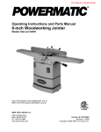
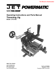
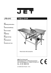
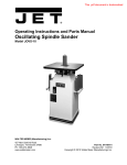
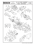
Operating Instructions — Parts Manual
Wilton Belt and Disc Sanding Machine
Model: 4210
WHM TOOL GROUP
2420 Vantage Drive
Elgin, Illinois 60123
Ph.: 800-274-6848
www.wmhtoolgroup.com
Part No. 5511717
Revision A8 02/05
Copyright © WMH Tool Group
This manual has been prepared for owners of Wilton Model 4210 Belt and Disc Sanding Machine. Its purpose is
to promote safety through the use of accepted operating and maintenance procedures. To obtain maximum life
and efficiency from your Belt and Disc Sander and to aid in using it safely, please read this manual thoroughly
and follow the instructions carefully.
Warranty
WMH Tool Group warrants every product it sells. If one of our tools needs service or repair, one of our Authorized
Repair Stations located throughout the United States can give you quick service.
In most cases, any one of these WMH Tool Group Repair Stations can authorize warranty repair, assist you in
obtaining parts, or perform routine maintenance and major repair on your JET, Wilton, Powermatic, or Performax
tools.
For the name of an Authorized Repair Station in your area, please call 1-800-274-6848, or visit
www.wmhtoolgroup.com
More Information
WMH Tool Group is consistently adding new products to the line. For complete, up-to-date product information,
check with your local WMH Tool Group distributor, or visit www.wmhtoolgroup.com
WMH Tool Group Industrial Metalworking Warranty
WMH Tool Group makes every effort to assure that its products meet high quality and durability standards and
warrants to the original retail consumer/purchaser of our products that each product be free from defects in
materials and workmanship as follows: TWO (2) YEAR LIMITED WARRANTY* ON ANY MECHANICAL
COMPONENT, ONE (1) YEAR LIMITED WARRANTY ON ANY ELECTRICAL COMPONENT. WMH This Warranty
does not apply to defects due directly or indirectly to misuse, abuse, negligence or accidents, normal wear-andtear, repair or alterations outside our facilities, or to a lack of maintenance.
WMH TOOL GROUP LIMITS ALL IMPLIED WARRANTIES TO THE PERIOD SPECIFIED ABOVE, FROM THE
DATE THE PRODUCT WAS PURCHASED AT RETAIL. EXCEPT AS STATED HEREIN, ANY IMPLIED
WARRANTIES OR MERCHANTIBILITY AND FITNESS ARE EXCLUDED. SOME STATES DO NOT ALLOW
LIMITATIONS ON HOW LONG THE IMPLIED WARRANTY LASTS, SO THE ABOVE LIMITATION MAY NOT
APPLY TO YOU. WMH TOOL GROUP SHALL IN NO EVENT BE LIABLE FOR DEATH, INJURIES TO PERSONS
OR PROPERTY, OR FOR INCIDENTAL, CONTINGENT, SPECIAL, OR CONSEQUENTIAL DAMAGES ARISING
FROM THE USE OF OUR PRODUCTS. SOME STATES DO NOT ALLOW THE EXCLUSION OR LIMITATION OF
INCIDENTAL OR CONSEQUENTIAL DAMAGES, SO THE ABOVE LIMITATION OR EXCLUSION MAY NOT APPLY
TO YOU.
To take advantage of this warranty, the product or part must be returned for examination, postage prepaid, to an
Authorized Repair Station designated by our office. Proof of purchase date and an explanation of the complaint
must accompany the merchandise. If our inspection discloses a defect, we will either repair or replace the
product, or refund the purchase price if we cannot readily and quickly provide a repair or replacement, if you are
willing to accept a refund. We will return repaired product or replacement at WMH Tool Group’s expense, but if it
is determined there is no defect, or that the defect resulted from causes not within the scope of WMH Tool Group’s
warranty, then the user must bear the cost of storing and returning the product. This warranty gives you specific
legal rights; you may also have other rights, which vary from state to state.
WMH Tool Group sells through distributors only. WMH Tool Group reserves the right to effect at any time, without
prior notice, those alterations to parts, fittings, and accessory equipment, which they may deem necessary for
any reason whatsoever.
∗
WMH Tool Group Industrial Metalworking’s 2 year limited warranty is based on one 8-hour work shift or 2080 hours per
year. The warranty period is good for 2 years of a total of 4160 hours whichever comes first.
Table of Contents
Cover Page ........................................................................................................................... 1
General Specifications .......................................................................................................... 4
Operating Precautions .......................................................................................................... 5
Introduction ........................................................................................................................... 7
Operating Instructions ........................................................................................................... 9
Maintenance ........................................................................................................................11
Wiring Diagram ................................................................................................................... 14
Troubleshooting .................................................................................................................. 16
Replacement Parts ............................................................................................................. 17
Wiring Diagram ................................................................................................................... 21
3
General Specifications
The Wilton Model 4210 Belt and Disc Sanding
Machine is ideal for all shops. This versatile machine
can be used to grind, sand, finish, and contour all
types of parts including metal, wood, plastic, and
composite materials. Because of these capabilities,
the Wilton sander eliminates the need for multiple
machines to perform the same tasks.
Specifications
4
Wilton Belt/Disc Sander, Model 4210
Belt Size
6" x 48"
Disc Size
10"
Motor
Horsepower
Voltage
1 HP
115/230 Vac (pre-wired for 115 Vac)
Switch
Removable Safety Key
Platen
Cast Iron
Tables
Cast Iron (2)
Belt Speed
1650 SFPM
Disc Speed
2100 RPM
Dust Collection Shrouds
Two (standard)
Weight
120 lbs.
General Machinery Cautions
- Misuse of this machine can cause serious injury.
- For safety, machine must be set up, used and
serviced properly.
- Read, understand and follow instructions in the
operator’s and parts manual which was shipped with
your machine.
When setting up machine:
- Always avoid using machine in damp or poorly
lighted work areas.
- Always be sure machine is securely anchored to
the floor.
- Always keep machine guards in place.
- Always put start switch in “OFF” position before
plugging in machine.
When using machine:
- Never operate with machine guards missing.
- Always wear safety glasses with side shields (See
ANSI Z87.1)
- Never wear loose clothing or jewelry.
- Never overreach — you may slip and fall into the
machine.
- Never leave machine running while you are away
from it.
- Always shut off the machine when not in use.
When servicing machine:
- Always unplug machine from electrical power while
servicing.
- Always follow instructions in operators and parts
manual when changing accessory tools or parts.
- Never modify the machine without consulting Wilton
Corporation.
You — the stationary power tool user — hold the key to safety.
Read and follow these simple rules for best results and full benefits from your machine. Used properly, Wilton’s
machinery is among the best in design and safety. However, any machine used improperly can be rendered
inefficient and unsafe. It is absolutely mandatory that those who use our products be properly trained in how to
use them correctly. They should read and understand the Operators and Parts Manual as well as all labels
affixed to the machine. Failure in following all of these warnings can cause serious injuries.
Machinery general safety warnings
1. Always wear protective eye wear when operating
machinery. Eye wear shall be impact resistant,
protective safety glasses with side shields which
comply with ANSI Z87.1 specifications. Use of eye
wear which does not comply with ANSI Z87.1 specifications could result in severe injury from breakage of
eye protection.
2. Wear proper apparel; no loose clothing or jewelry
which can get caught in moving parts. Rubber soled
footwear is recommended for best footing.
3. Do not overreach. Failure to maintain proper
working position can cause you to fall into the
machine or cause your clothing to get caught —
pulling you into the machine.
4. Keep guards in place and in proper working
order. Do not operate the machine with guards
removed.
5. Avoid dangerous working environments. Do not
use stationary machine tools in wet or damp locations. Keep work areas clean and well lit.
6. Avoid accidental starts by being sure the start
switch is “OFF” before plugging in the machine.
7. Never leave the machine running while unattended.
8. Disconnect electrical power before servicing.
Whenever changing accessories or general maintenance is done on the machine, electrical power to the
machine must be disconnected before work is done.
9. Maintain all machine tools with care. Follow all
maintenance instructions for lubricating and the
changing of accessories. No attempt shall be made
to modify or have makeshift repairs done to the
machine. This not only voids the warranty but also
renders the machine unsafe.
10. Machinery must be anchored to the floor.
11. Secure work. Use clamps or a vise to hold work,
when practical. It is safer than using your hands and
it frees both hands to operate the machine.
12. Never brush away chips while the machine is in
operation.
13. Keep work area clean. Cluttered areas invite
accidents.
14. Remove adjusting keys and wrenches before
turning machine on.
15. Use the right tool. Don’t force a tool or attachment to do a job it was not designed for.
16. Use only recommended accessories and follow
manufacturers instructions pertaining to them.
17. Keep hands in sight and clear of all moving parts
and cutting surfaces.
18. All visitors should be kept at a safe distance from
the work area. Make workshop completely safe by
using padlocks, master switches, or by removing
starter keys.
19. Know the tool you are using — its application,
limitations, and potential hazards.
5
General Electrical Cautions
Wire sizes
This machine should be grounded in accordance with
the National Electrical Code and local codes and
ordinances. This work should be done by a qualified
electrician. The machine should be grounded to
protect the user from electrical shock.
Caution: for circuits which are far away from the
electrical service box, the wire size must be increased in order to deliver ample voltage to the motor.
To minimize power losses and to prevent motor
overheating and burnout, the use of wire sizes for
branch circuits or electrical extension cords according to the following table is recommended:
Conductor length
0-50 feet
50-100 feet
Over 100 feet
AWG (American wire gauge) number
240 volt lines 120 volt lines
No. 14
No. 14
No. 12
No. 14
No. 8
No. 12
Safety Requirements for Abrasive Sanding Machines
6
Abrasive sanding can be hazardous to operators and
bystanders. Sanding sparks, chips and dust particles
thrown off by the sanding disc can cause serious
injury by contact or inhalation. To avoid injuries you
must comply with the following safety requirements:
1. Always wear protective eyewear when operating
machinery. Eye wear shall be impact resistant,
protective safety glasses with side shields which
comply with ANSI Z87.1. Use of eye wear which
does not comply with ANSI Z87.1 specifications could
result in severe injury from breakage of eye protection. See Figure A, below.
2. Wear leather safety gloves, arm guards, leather
aprons and safety shoes.
3. A dust collection system is recommended,
Operator shall also wear a dust mask at all times.
See Figure B, below.
4. Additional precautions may be necessary for
sanding materials which are flammable or have other
hazardous properties. You should always consult the
manufacturer of such materials for instructions on
sanding and handling.
5. Do not force or jamb the workpiece into the
sanding disc.
6. Before sanding, always allow the motor to come
up to operating speed, then check the sanding disc
Figure A
Figure B
for wobble, runout, or any unbalanced condition. If
the disc is not operating accurately and smoothly,
immediately stop the motor and make repairs before
attempting any sanding operations.
7. Abrasive discs must be stored in a controlled
environment area. Relative humidity should be 35%
to 50% and the temperature should be between 60
and 80 degrees Farenheit. Failure to do so could
cause premature disc failure.
8. Examine the face of the sanding disc carefully.
Excessive sanding which wears down to the backing
material can tearing of the disc. Never use a disc
which shows backing, nicks or cuts on the surface or
edge or damage due to creasing or poor handling.
9. When installing a new disc, be certain the disc is
accurately centered on the drive wheel. Failure to do
so could cause a serious unbalanced condition.
10. Always present the workpiece to the wheel while
resting the workpiece firmly on the table. Failure to
do so could result in damage to the workpiece or
throwing of the workpiece off the wheel.
11. Safety shoes which comply with ANSI Z41.1 shall
be worn. See Figure C.
12. Personal hearing protection such as ear plugs or
ear muffs shall be used to protect against the effect
of noise exposure. See Figure D.
Figure C
Figure D
Introduction
This manual includes operating and maintenance
instructions for the Wilton Model 4210 Belt and Disc
Sander. This manual also includes parts listings and
illustrations of replaceable parts.
Sanding Belt
Belt Guard
Platen Housing
Belt and Disc Sander
Features
Figures 1 and 2 depict the main features of the
Wilton Model 4210 Belt and Disc Sander. (Specifications for the sanding machine are provided on page
3.)
Belt Sander
Work Table
Debris Duct
On/Off
Switch
Machine
Base
Tracking Adjustment
Belt Tensioning Lever
Stand
Belt Work Table
Clamping Knob
Sanding Disk
Disc
Debris
Duct
Power Cord
Miter Gauge
Figure 2: Belt and Disc Sander Features
(Left Side View)
The sander has both a sanding belt and a sanding
disc for use on a variety of work pieces and materials.
Disc Work Table
Clamping Knob
Figure 1: Belt and Disc Sander Features
(Right Side View)
The platen housing for the belt sander can be positioned vertically or horizontally. When in the vertical
position, the drum at the upper end of the platen
housing can be used for contouring. A tracking
adjustment mechanism for the sanding belt is provided at the upper end of the platen housing.
The platen housing has a lever that is used to apply
tension to the sanding belt. The sanding belt is easily
replaced by releasing the tension lever, removing a
sanding shroud and dust collection duct at the bottom
of the platen housing, and slipping the belt from the
belt sander drums. Installation is the reverse of the
removal steps.
7
The disc sander consists of an aluminum disc onto
which is installed an adhesive-backed sanding and
other abrasive discs. The disc is contained within a
ducted shroud.
The sanding disc can be replaced by removing the
table and a cover over the lower portion of the disc.
If desired, the aluminum disc can be removed from
its drive shaft to ease replacement of the sanding
disc.
The drive motor for the belt and disc sander is
attached to the underside of the machine base. An
ON/OFF switch is mounted on the machine base on
the side opposite the disc sander. Electrical wiring
for the motor enters the machine base below the ON/
OFF switch and is routed to the switch and motor
inside the machine base.
The belt and disc sander is driven by V-belts connected to the drive motor. A pulley on the motor shaft
drives a V-belt that drives a dual-groove pulley on an
idler shaft. A second V-belt is installed in the second
groove of the dual-groove pulley and connects to a
pulley on belt sander drive shaft.
The aluminum sanding disc is driven off the end of
the idler shaft. A shaft connected to the second Vbelt pulley drives the belt sander drive drum.
The belt and disc sander is mounted on a stand that
can be secured to the floor to stabilize the machine.
The stand has a door for access to the fasteners for
the machine base.
8
Installation and Setup
Mounting
It is recommended that the belt and disc sander be
secured to the floor for safe operation. The machine
stand has mounting holes in a flange on the inside of
stand enclosure. The stand can be secured to the
floor using these mounting holes.
Electrical Connection
Refer to the Wiring Data section for wiring information. Electrical power should be connected by a
qualified electrician. Observe local electrical codes
when connecting and grounding the machine.
Operation
This section defines the controls and other features
with which the operator should be familiar. Refer to
Figures 3 and 4 for some typical sander operations.
Figure 5. ON/OFF Switch
Miter Gauge
A miter gauge is provided with the machine and can
be used on either the belt sander of disc sander work
tables. The angle of the miter gauge can be adjusted
up to 45 degrees to accommodate angular work
piece surfaces.
Adjustments
Adjusting Belt Tracking
Figure 3. Contouring with Belt Sander
The tracking of the sanding belt may require adjustment after changing the belt. The belt housing has a
tracking adjustment mechanism (Figure 6) that is
used to adjust tracking.
1. Start the machine.
2. Check tracking of the sanding belt. The belt
should track at the center of the drums.
3. Adjust belt tracking by turning the adjustment
knob. Turn the knob as needed to correct the
tracking of the belt.
9
Belt should track
at center of drums;
no side-to-side
movement.
Belt Tracking
Adjustment Knob
Figure 4. Sanding using Disc Sander
Controls
Belt Tensioning
Lever
The ON/OFF switch is located on the side of the
machine base (refer to Figure 5).
Figure 6. Adjusting Belt Tracking
Adjusting Platen Housing
Position
The sanding belt can be operated with the platen
housing horizontal, vertical, or at any angle in
between. Change position of the platen housing as
follows:
Disc Table
1. To change the disc table angle, loosen the knob
on the left side of the table (refer to Figure 8).
2. Move the table to the desired angle.
3. Tighten the knob to secure the table.
WARNING: DISCONNECT ELECTRICAL POWER
TO THE MACHINE BEFORE PERFORMING ANY
MAINTENANCE.
1. Disconnect electrical power.
2. Remove four screws (52) and pulley cover (12).
3. Using an open end wrench, loosen two hex
screws (13) (refer to Figure 7).
4. Move the platen housing to the desired position.
When the platen housing is to be placed in the
horizontal position, lower the platen housing onto
stop screw (28) on the machine base.
5. If the stop requires adjustment, loosen jam nut
(29), adjust stop screw (28) to desired position,
and tighten nut (29).
6. Tighten two hex screws (13).
7. Install pulley cover (12) and secure with four
screws (52).
8. Start the machine to check operation.
Belt Table
Clamping Knob
Belt Table Angle Scale
(left underside of table)
Disc Table Angle Scale
Table Clamping Knob
Figure 8. Adjusting Sander Table Angle
10
Belt Table
Clamping
Screws
Platen
Housing
Figure 7. Platen Housing Clamping Screws
Adjusting the Sander Tables
The belt and disc sander tables can be adjusted
from 0 to 45 degrees to accommodate the work
piece.
1. To change the belt table angle, loosen the knob
on the right side of the platen housing (refer to
Figure 8).
2. Move the table to the desired angle.
3. Tighten the knob to secure the table.
Maintenance
This section provides procedures required to maintain the belt/disc sander. The numbers in parentheses throughout the manual correspond with reference
numbers for parts shown in the exploded views in the
Replacement Parts section.
Lubrication
The bearings used in the sanding machine are
sealed, pre-lubricated bearing. The bearings do not
require periodic lubrication.
Cleaning
Periodically use a vacuum cleaner to remove sanding
debris from the machine. In hard to reach areas,
brush the debris loose while vacuuming.
Replacing the Sanding Belt
WARNING: DISCONNECT ELECTRICAL POWER
TO THE MACHINE BEFORE PERFORMING ANY
MAINTENANCE.
1. Disconnect electrical power.
2. Position sanding belt platen (4) in the vertical
position. Remove eight screws (97) and guard
(96).
3. Remove screw (76) and guard (75).
4. Move tensioning lever (50) downward to slacken
sanding belt (79).
Refer to Figure 9. Slip sanding belt off drums (5) and
(39).
Figure 9. Replacing Sanding Belt
1. Install replacement sanding belt on drums.
Position edges of sanding belt evenly on the
drums.
2. Lift tensioning lever to tighten sanding belt on
drums.
3. Install guard (75) and secure with screw (76).
4. Install guard (96) and secure with eight screws
(97).
5. Connect electrical power and operate machine to
check operation.
6. If belt does not track properly, adjust tracking
(refer to Adjusting Belt Tracking).
Replacing the Sanding Disc
WARNING: DISCONNECT ELECTRICAL POWER
TO THE MACHINE BEFORE PERFORMING ANY
MAINTENANCE.
1. Disconnect electrical power.
2. Loosen screw (65). Remove disc table (60).
3. Remove four screws (56) and plate (55) from
disc shroud (53).
4. Insert a long T-handle Allen wrench through the
side opening in shroud (53) and into set screw
(57). Loosen disc set screw (57) and remove
disc (58).
WARNING: USE CARE WHEN USING KNIFE TO
SEPARATE SANDING DISC (59) FROM DISC (58).
INJURY FROM THE KNIFE MAY OCCUR IF THE
KNIFE SLIP OR IF SANDING DISC SHOULD
SUDDENLY COME FREE.
5. Using a knife, slowly work the tip of the knife
blade under sanding disc (59). Slowly work the
tip around the circumference of disc (58).
Continue to work around the circumference until
sanding disc can be separated by hand from
disc (58).
6. Remove paper backing from replacement sanding disc (59). Place sanding disc (59) on disc
(58). Make sure the sanding disc is place evenly
at the outside diameter of disc (58).
7. Press on the sanding disc to remove any entrapped air and to make sure the sanding disc is
adhering to disc (58).
8. Install disc (58) onto shaft (16). Position the disc
on the shaft to provide clearance between plate
(55) and sanding disc. Tighten set screw (57).
NOTE: There is a close fit between the edge of disc
(58) and disc shroud. To ease installation and positioning of the disc, use an L-shaped tool (such as an
Allen wrench) under outer edge of the disc to support
and position the disc while tightening set screw.
11
9. Install plate (55) and secure with four screws
(56). Check for clearance between plate (55)
and the sanding disc.
10. Install table (60) onto rod (74). Position table so
it is level and tighten screw (65) against rod (74).
11. Connect electrical power and operate machine to
check operation.
Replacing the V-Belts
WARNING: DISCONNECT ELECTRICAL POWER
TO THE MACHINE BEFORE PERFORMING ANY
MAINTENANCE.
1.
2.
3.
4.
5.
6.
7.
8.
9.
10.
11.
Disconnect electrical power.
Remove sanding belt table.
Remove sanding disc table.
Remove sanding disc and shroud.
Remove pulley cover. Loosen set screw in pulley.
With second person holding belt housing,
alternately loosen and remove two screws.
Remove V-belt from pulley (11). Remove pulley
from shaft while separating assembled belt
housing from the machine base.
Remove key from sanding belt drum shaft.
Loosen set screw in pulley (20).
Remove pulley. While removing pulley, slip Vbelts from pulley.
Remove four screws from base. With assistance
of the second person, lift base from stand.
NOTE: Place base on bench. As an alternative, the
stand may be used to support the base while removing drive motor screws.
12
12. Place base on bench with underside of the base
facing up.
13. Remove two hex head screws, two nuts, and two
washers from the motor base on the shaft side of
motor.
14. Loosen (but do not remove) two hex bolts, two
nuts, and two washers on the side of motor base
opposite the motor shaft.
15. Tip motor enough to provide clearance between
end of shaft and wall of base. Remove motor
drive belt.
16. With base still on the bench, slip V-belt (15) over
end of idler shaft.
NOTE: Install V-belt for sanding belt first, followed by
the motor V-belt.
17. Install replacement V-belt over end of motor shaft.
18. Install two hex bolts, two nuts, and two washers in
the motor base on the shaft side of motor.
Tighten all four hex nuts and hex head screws.
19. Install key in idler shaft with keyway facing up.
Install pulley (20) on idler shaft.
20. Install motor V-belt (18) in outermost groove of
pulley (20) and on pulley (18) on motor shaft.
21. Position motor belt (18) on idler shaft so it is
parallel with the inner wall of the base. Tighten
set screw in pulley (20).
22. Place assembled base on stand. Secure with
four screws, washers, nuts.
NOTE: Because of the weight of the belt housing, a
second person should hold the belt housing in
position while installing pulley (10).
23. Hold belt housing in position in bracket (3). Start
two screws (13) in threaded holes in platen.
Install key (8) in shaft.
NOTE: Because of the length of screws (13), the
screws will have to be installed alternately. As the
screws are installed, there will be enough clearance
to slide the belt drum drive pulley a little at a time onto
shaft (8).
24. Alternately install two screws (13). As the screws
are tightened, slide pulley (10) onto the idler shaft
as allowed by the protrusion of screw heads.
Make sure V-belt remains on pulleys (11 and 20).
25. When screws (13) are fully installed, align pulley
(20) with pulley (11). Tighten set screw (10).
26. Install shroud (53) on base and secure with four
screws and washers.
27. Install pulley cover (12) and secure with two
screws.
28. Install disc (58) onto shaft (16) and over key.
Position the disc on the shaft to provide clearance between plate (55) and the sanding disc.
Using long T-handle Allen wrench, tighten set
screw (57).
NOTE: There is a close fit between the edge of disc
(58) and the disc shroud. To ease installation and
positioning of the disc, use an L-shaped tool (such as
an Allen wrench) under the outer edge of the disc to
support and position the disc while tightening the set
screw.
29. Install plate (55) and secure with four screws
(56). Check for clearance between plate (55)
and the sanding disc.
30. Install table (60) onto rod (74). Position table so
it is level and tighten screw (65) against rod (74).
31. Install assembled table (88).
32. Connect electrical power and operate machine to
check operation.
Replacement of Motor
WARNING: DISCONNECT ELECTRICAL POWER
TO THE MACHINE BEFORE PERFORMING ANY
MAINTENANCE.
1. Disconnect electrical power.
2. Remove four screws from base. With assistance
of the second person, lift base from stand.
NOTE: Place base on bench. As an alternative, the
stand may be used to support the base while removing drive motor screws.
3. Place base on bench with underside of the base
facing up.
4. Remove four hex head screws, nuts, and washers from the motor base.
5. Remove motor V-belt from motor pulley.
6. Remove motor from base.
7. Loosen set screw in pulley (18). Remove pulley.
8. Align set screw in pulley with flat on motor shaft
and install pulley. Do not tighten set screw.
9. Install replacement V-belt over end of motor shaft
and install motor in base . Secure with four
screws, washers and nuts.
10. Install and tighten four hex bolts, nuts, and
washers in the motor base.
11. Position pulley (18) on motor shaft so the V-belt
is parallel with the inner wall of the base. Tighten
set screw in pulley (20) against flat on motor
shaft.
12. Place assembled base on stand. Secure with
four screws, washers, nuts.
13. Connect electrical power and operate machine to
check operation.
13
Wiring Data
Single phase electrical hook-up
When connecting your machine to single phase
power you may be connecting to either 115 or 230
volts, depending upon the motor type provided. Local
codes may, or may not, permit the use of a plug type
of connection for your machine. Where a plug
connection is permitted, the following installation
practices must be followed:
1. The plug used must be a grounding type of plug.
On a 115 volt single phase connection, the plug
must be a three-prong plug with two flat, parallel
blades for the power wires and a single rounded
or U-shaped prong for the ground connection.
On 230 volt single phase connections, the lug
must be a three prong plug with two flat blades in
tandem to carry the current, and a third round or
U-shaped prong for the ground connection.
2. The service branch to which the plug is connected
must be a branch with a separate ground wire so
the grounding prong of the plug can be connected to ground effectively.
Note: Local electrical codes in many jurisdictions do
not allow the use of plug type connections for single
phase power when the machine is used in a commercial or industrial establishment.
In these cases you must connect your machine to
the service branch using a hard-wired junction box
connection.
All Wilton sanders are shipped with the power cable
terminating without a plug on the assumption the
machine will be hard-wired to its service branch.
Circuit protection
Where the service branch is protected with a fuse or
circuit breaker which is too high a value to offer
protection to the motor supplied, a fuse or circuit
breaker box should be used at the point where the
machine connection is made and the time delay fuse
or circuit breaker should be a value just slightly
higher than the maximum load current draw as
specified on the motor plate on the motor.
Correcting motor rotation in single
phase motors
Wilton provides single phase motors in both 115 volt
and 230 volt configuration. Several motor manufactures may be used by Wilton for motors of this type.
These motors may, or may not, rotate in the correct
direction -- counter-clockwise -- when connected to
your single phase power source. If, after connection, the motor runs in the correct counter-clockwise
direction, the power connection is successful.
14
Figure 10: Pictoral diagram for single
phase motor, 115 volts w/plug.
CAUTION: IF THE MOTOR RUNS CLOCKWISE
WHEN CONNECTED TO YOUR SINGLE PHASE
POWER SOURCE, YOU MUST DISCONNECT THE
POWER SOURCE, OPEN THE JUNCTION BOX
AND FIND THE CORRECT WIRING CONNECTIONS
FOR THE MOTOR, OR LOCATE THE WIRING
CONNECTIONS REQUIRED ON THE MOTOR PLATE
ON THE OUTSIDE OF THE MOTOR.
Different manufacturers provide different wiring
configurations for correcting the rotation of the motor
armature. Therefore, no wiring diagrams for these
motors are provided in this manual. Always consult
the motor plate and/or the wiring diagram inside the
junction box if rotation direction is not correct.
Figure 11: Pictoral diagram for
3-phase motor.
Connecting Power for 3-phase Motors
1. Be certain the power to the branch you are
connecting is off, and locked out, so power
cannot be reestablished, accidentally.
2. Connect the ground wires. Thse wires will be
either green, or green with a white trace.
3. Connect the remaining three cable wires to the
three power wires in the service branch.
4. Reestablish power to the branch.
5. Turn the machine on. The motor should be
turning counter-clockwise, the belt sander should
be moving downward, and the disc sander should
6.
7.
8.
9.
be turning clockwise. If this is the case, the
machine can be considered wired correctly. If
the motor is not turning in the correct direction,
take the following corrective action:
Disconnect power in the branch again and be
certain it cannot be accidentally turned on while
you correct the wiring.
Reverse ANY TWO of the power wires to the
machine.
Reestablish power in the service branch to the
machine.
Turn on the machine again. The motor should
now be turning in the correct direction.
Figure 12: Schematic diagram for
single phase motor with 3-wire
cable. Note: this schematic
provided for use with older
sanders, only. All machines are
now shipped with a 4-wire cable
whether single phase or 3-phase.
Figure 13: Schematic diagram for
single phase motor with 4-wire
cable.
15
Figure 14: Schematic diagram for
3-phase motor.
Troubleshooting
Fault
Probable Cause
Remedy
Machine does not start.
1. Blown fuse or tripped
circuit breaker.
1. Determine reason for blown fuse/tripped
breaker (such as a short circuit or motor
overload). Correct reason for fault. Replace
fuse/reset breaker.
2. Replace motor.
3. Connect to power source.
2. Motor failure.
3. Not connected to power
source.
4.Motor not wired for correct
voltage.
5. Motor not connected to
correct voltage source.
Sanding belt does not
trackcorrectly.
16
1. Sanding belt stretched
unevenly.
2. V-belt worn.
3. Pulley worn.
4. Correct motor wiring.
5. Connect to proper voltage source.
1. Replace sanding belt.
2. Replace V-belt.
3. Replace pulley.
Abrasive disc separates
from disc.
1. Improperly bonded.
1. Clean residual adhesive from disc.
Reapply adhesive-backed disc to clean disc.
Sanding belt slips or stalls
when pressure is applied.
1. Abrasive belt tension
inadequate.
2. Excessive pressure being
applied to platen housing.
3. Motor belt loose.
1. Tighten sanding belt.
2. Reduce pressure on sanding belt
(and platen housing).
3. Tighten motor belt.
Disc stalls when pressure
is applied.
1. Motor V-belt loose.
1. Tighten motor V-belt.
Frequent replacement of
sanding belt.
1. Too much pressure being
applied to work piece.
2. Full width of belt not being
used.
1. Reduce pressure on work piece.
2. Stroke across sanding belt using full width
of belt surface.
Replacement Parts
This section provides exploded view illustrations that show the replacement parts for the Wilton Model 4210 Belt/
Disc Sander. Also provided are parts listings that provide part number and description. The item numbers
shown on the illustration relate the item number in the facing parts listing.
Order replacement parts from:
WHM TOOL GROUP
2420 Vantage Drive
Elgin, Illinois 60123
Ph.: 800-274-6848
www.wmhtoolgroup.com
To order parts or reach our service department, call 1-800-274-6848 between 7:30am and 5:30pm (CST),
Monday through Friday. Having the Model Number and Serial Number of your machine available when you call
will allow us to serve you quickly and accurately.
.
17
Assembled View and Parts Listing of Stand –
Model 4210 Belt and Disc Sander
3
2
1
18
Ref.
No.
Part
Number
Description
Qty.
1
2
3
5513476
5513477
5515307
Panel, Access
Knob
Stand, Complete
1
2
1
Exploded View – Wilton Model 4210 Belt & Disc Sander
19
Parts Listing – Wilton Model 4210 Belt & Disc Sander
20
Ref.
No.
2
3
4
5
6
7
8
8A
9
10
11
12
13
14
15
16
17
18
20
21
22
23
24
25
26
27
28
29
30
31
32
33
34
35
36
37
38
39
40
41
42
43
Part
Number
5513011
5513012
5513013
5513014
5513015
5513016
5513017
5513028
5513018
5513019
5513020
5513021
5513022
5513023
5513024
5513025
5513026
5513027
5513029
5513030
5513031
5513032
5513033
5512767
5513035
5513036
5513037
5513038
5513039
5513040
5513041
5513042
5513043
5513044
5513045
5513046
5513047
5513048
5513049
5513050
5513051
5513052
44
45
46
47
48
49
50
51
52
53
54
55
56
5513054
5513055
5513056
5513057
5513058
5513059
5513060
5513061
5513062
5513063
5513064
5513065
5513066
Description
Base
Bracket
Platen
Drum, Drive
Shaft, Drum Drive
Bearing (6203ZZ)
Key
Key
Ring, Retaining (S-17)
Screw, Set (1/4 X 3/8)
Pulley
Cover, Pulley
Screw (5/16 X 1-1/2)
Washer, Plain (5/16)
V-Belt (A-18)
Shaft, Drive Pulley
Bracket
Pulley, Motor
Pulley, Idler
V-Belt (A-25)
Screw (5/16 X 3/4)
Washer, Flat (5/16)
Nut, Hex (5/16)
Motor, 1-HP
Screw, Hex (3/8 X 1)
Washer, Flat (3/8)
Screw (3/8 X 1-1/2)
Nut, Jam
Bracket, Mounting
Screw (5/16 X 1)
Washer (1/4)
Screw, Hex (1/4 X 3/4)
Spring (1/4)
Shaft
Shaft, Driven Drum
Ring, Retaining (S-15)
Bearing (6202ZZ)
Drum, Driven
Nut (1/4)
Spring
Washer, Flat
Rod, Threaded, Belt
Tracking Adjustment
Support, Driven Drum
Screw (5/16 X 1/2)
Bracket
Bar
Screw (3/16 X 1/2)
Washer (3/16)
Lever, Belt Tension
Screw (5/16 X 1-1/4)
Screw (3/16 X 3/8)
Guard, Disk
Washer, Lock (3/16)
Plate, Cover
Screw (3/16 X ¼)
Qty
1
1
1
1
1
2
1
1
2
1
1
1
4
4
1
1
1
1
1
1
4
8
4
1
3
3
1
1
1
1
6
2
1
1
1
2
2
1
1
1
1
1
1
1
1
1
6
2
1
1
2
1
4
1
5
Ref.
No.
57
58
59
Part
Number
5513067
5512765
5513071
5513073
5513075
60
5513077
61
5513078
62
5513079
63
5513080
64
5513081
65
5513082
66
5513083
67
5513084
68
5513085
69
5513086
70
5513087
71
5513088
72
5513089
73
5513090
73A 5513091
74
5513092
75
5513093
76
5513094
77
5513095
77A 5513096
78
5512766
79
5051841
Description
Screw, Set (6 X 10 MM)
Disk, Aluminum
Garnet Disk 10":
80 Grit (Standard)
Also available:
100 Grit
120 Grit
Table, Side
Support, Table
Bracket, Table Support
Pin, Spring
Screw (1/4 X 3/8)
Screw, Hex (5/16 X 1)
Pin, Spring
Bracket, Table Support
Washer, Flat
Pointer
Knob
Washer
Rivet
Scale
Pointer
Rod, Table Support
Guard, Belt
Screw (3/16 X 5/8)
Cover, Sanding Belt*
Screw, Cap*
Switch
Belt, Abrasive(6 x 48)
80 Grit (Standard)
Also available:
100 Grit
150 Grit
Washer
Knob (1/4 X 1-1/2)
Bracket, Table
Screw (5/16 X 1-1/2)
Pin (4 X 15)
Table, Sanding Belt
Wrench*
Screw, Socket Head
Washer, Flat
Nut, Hex
Screw, Hex Head
Washer, Flat
Nut, Hex
Cover, Belt
Screw, Socket Head
Guard, Belt
Screw
Gauge, Miter
Head, Complete
82
83
84
85
86
88
89
90
91
92
93
94
95
96
97
98
99
100
5512764
5513103
5513107
5513108
5512763
5513110
5513111
5513113
5513114
5513115
5513116
5513117
5513118
5513119
5513120
5513479
5513480
5514639
5514640
5517426
5515308
*
Part not shown.
Qty
1
1
1
1
1
1
1
1
1
4
1
1
1
2
1
1
1
3
1
1
1
1
1
1
8
1
1
1
1
1
1
1
3
1
1
1
2
2
2
2
2
2
1
8
1
4
1
1
Wiring Diagram
4210 ELECTRICAL SCHEMATIC - 115V
SWITCH
BLACK
BLACK
WHITE
WHITE
GREEN
300MFD 125 VAC
YELLOW
BLACK
GREY
RED
GREEN
GREEN
BLACK
WHITE
GROUND
4210 ELECTRICAL SCHEMATIC - 230V
SWITCH
BLACK
BLACK
WHITE
WHITE
GREEN
21
300MFD 125 VAC
BLACK
GREY
YELLOW
RED
GREEN
GREEN
BLACK
WHITE
GROUND
Notes
Notes
WHM TOOL GROUP
2420 Vantage Drive
Elgin, Illinois 60123
Ph.: 800-274-6848
www.wmhtoolgroup.com