1
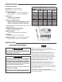
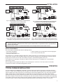
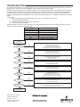
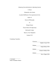
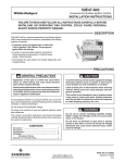
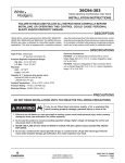
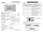
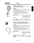
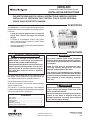
50D50-843
Universal Proven Pilot Spark Control
INSTALLATION INSTRUCTIONS
FAILURE TO READ AND FOLLOW ALL INSTRUCTIONS CAREFULLY BEFORE
INSTALLING OR OPERATING THIS CONTROL COULD CAUSE PERSONAL
INJURY AND/OR PROPERTY DAMAGE.
DESCRIPTION
The 50D50-843 is a universal replacement Spark control
designed for maximum compatibility with existing systems.
It features:
•
•
•
A card port and ten program keys to select the
Safety Time, Retries, Pre-purge and Recycle
timings.
A Jumper to accommodate systems using Direct
Sense (sensing through ignitor) or Indirect Sense
(using a Flame Sensor)
LED indicator for quick system and module diagnostics
and troubleshooting.
PRECAUTIONS
! GENERAL PRECAUTION
! CAUTION
Application of this type of control may cause
flame rollout on initial startup and could cause
personal injury and/or property damage.
To prevent electrical shock and/or equipment
damage, disconnect electric power to system at
main fuse or circuit breaker box until installation
is complete.
Check product specification and cross reference
before replacing existing module. Do not use if
existing module is not listed. Use of a program
key other than listed can result in appliance
malfunction.
If in doubt about whether your wiring is millivolt, line, or
low voltage, have it inspected by a qualified heating and
air conditioning contractor or licensed electrician.
Label all wires prior to disconnection when
servicing controls. Wiring errors can cause
improper and dangerous operation.
This control is not intended for use in locations
where it may come in contact with water. Suitable
protection must be provided to shield the control
from exposure to water (dripping, spraying,
rain, etc.).
Do not exceed the specification ratings.
All wiring must conform to local and national electrical
codes and ordinances.
! WARNING
This control is a precision instrument, and should be
handled carefully. Rough handling or distorting components
could cause the control to malfunction.
Do not use on circuits exceeding specified voltage.
Higher voltage will damage control and could
cause shock or fire hazard.
CONTENTS
Description ..................................................................
Precautions .................................................................
Specifications ..............................................................
Installation ...................................................................
Mounting & Wiring........................................................
Operation & Troubleshooting .......................................
1
1
2
2
2
3
Do not short out terminals on gas valve or primary
control to test. Short or incorrect wiring will
damage thermostat and could cause personal
injury and/or property damage.
PART NO. 37-6576H
www.white-rodgers.com
www.emersonclimate.com
Replaces 37-6576G
1423
SPECIFICATIONS
Program Key Timing Specifications Quick Reference
ELECTRICAL RATINGS:
Timing and Retry
Input Voltage: 18 to 30 VAC, 60 Hz
Current: 0.2 amp + MV + PV @ 25 C
O
Relay Contact Ratings:
Pilot Valve Relay: 1.5 amp @ 25 VAC 60 Hz
Main Valve Relay: 1.5 amp @ 25 VAC 60 Hz
Spark Output:
Gap: 0.1" - 0.2", 15kV 25Hz
Max cable length 3ft (0.9m)
Flame Current Requirements:
Minimum current to insure flame detection: 2 µA DC*
Maximum current for non-detection: 0.2 µA DC
Maximum allowable leakage resistance: 100 M ohms
* Measured with a DC microammeter in series with the
flame probe lead
PROGRAM
KEY
(COLOR)
A (blue)
B (red)
C (green)
D (violet)
E (orange)
F (yellow)
G (blue\red)
H (red\green)
I (green\orange)
J (violet\blue)
PRE-
PURGE
RESET
SAFETY
TIME
TIME
RETRIES
TIME
0 Sec.
300 Sec. Continuous 90 Sec.
30 Sec.
300 Sec. Continuous 90 Sec.
0 Sec.
300 Sec. Continuous 30 Sec.
30 Sec.
300 Sec. Continuous 30 Sec.
0 Sec.
300 Sec.
2
60 Sec.
30 Sec.
300 Sec.
2
60 Sec
0 Sec.
300 Sec. Continuous 15 Sec.
30 Sec.
N/A
N/A
Continuous
0 Sec.
300 Sec. Continuous
4 Sec.
30 Sec.
300 Sec. Continuous
4 Sec.
Program Key
OPERATING TEMPERATURE RANGE:
-40° to 175°F (-40° to 80°C)
HUMIDITY RANGE:
To 95% relative humidity (non-condensing)
MOUNTING:
Surface mount or 4" x 4" junction box
GASES APPROVED: Natural, Manufactured, Mixed,
Liquid Petroleum, and LP Gas Air Mixtures.
Fig. 1 – Program Key installation
INSTALLATION
MOUNTING AND WIRING
! WARNING
Do not use on circuits exceeding specified voltage. Higher voltage will damage control and could
cause shock or fire hazard.
! CAUTION
To prevent electrical shock and/or equipment
damage, disconnect electric power to system at
main fuse or circuit breaker box until installation
is complete. Failure to earth ground the appliance
or reversing the neutral and hot wire connection
to the line can cause shock hazard.
2
NOTE
Replace control as unit – no user serviceable parts.
All wiring should be installed according to local and national
electrical codes and ordinances.
The control may be mounted in any orientation on a
convenient surface using two #6 x 5/8” sheet metal screws.
If desired, control can be mounted on a 4” x 4” junction
box using two #8-32 x 5/8” machine screws. The control
must be secured to an area that will experience a minimum
of vibration and remain below the maximum ambient
temperature rating of 175°F. The control is approved for
minimum ambient temperatures of –40°.
Refer to the wiring diagrams and wiring table when
connecting the control to other components of the system.
Shut off main gas to heating system until
installation is complete.
UL approved 105°C rated 18 gauge minimum wire is
recommended for all low voltage connections. UL approved
105°C rated 16 gauge minimum wire is recommended for all
line voltage connections.
Route and secure all wiring as far from flame as
practical to prevent fire and/or equipment damage.
After installation or replacement, follow appliance
manufacturer’s recommended installation/service instructions
to insure proper operation.
Gas
Valve
**FLAME
PROBE
PV
SPARK
FLY
LEAD
TH
GND
TR
PV
MV
*SPARK
PROBE
JUMPER
LINK
MV
FLAME
(GND)
VAL
SPARK
GND
MV
Gas
Valve
FLY
LEAD
TH
TR
PV
MV
VAL
INSTALLATION
FLAME
(GND)
PV
Burner Ground
Burner Ground
LIMIT
CONTROLLER
(GND)
*SPARK
PROBE
LIMIT
CONTROLLER
(GND)
L1 (HOT)
L1 (HOT)
L2
L2
THERMOSTAT OR
CONTROLLER
TRANSFORMER
MV
Gas
Valve
PV
Burner Ground
WHITE
LIMIT
CONTROLLER
L1 (HOT)
L2
ALTERNATE
LIMIT
TRANSFORMER
Fig. 4 – Typical hookup for White-Rodgers replacement with
vent damper and separate flame-sense and spark probes
*SPARK
PROBE
FLAME
(GND)
PV
Burner Ground
GREY
Vent
Damper
Plug
SPARK
FLY
LEAD
TH
GND
TR
JUMPER
LINK
MV
Gas
Valve
**FLAME
PROBE
ORANGE
THERMOSTAT OR
CONTROLLER
TRANSFORMER
*SPARK
PROBE
(GND)
RED
ALTERNATE
LIMIT
Fig. 3 – Typical hookup for White-Rodgers replacement with
direct flame sense throughsingle spark/sense probe
MV
SPARK
FLY
LEAD
FLAME
(GND)
GREY
Vent
Damper
Plug
GND
TH
TR
PV
VAL
MV
Fig. 2 – Typical hookup for White-Rodgers replacement with
separate flame-sense and spark probes
PV
ALTERNATE
LIMIT
VAL
THERMOSTAT OR
CONTROLLER
WHITE
LIMIT
CONTROLLER
(GND)
RED
L1 (HOT)
ORANGE
THERMOSTAT OR
CONTROLLER
L2
ALTERNATE
LIMIT
TRANSFORMER
Fig. 5 – Typical hookup for White-Rodgers replacement with vent
damper and direct flame sense through single spark/sense probe
* Max length of spark cable should be less than 3ft (0.9m) and rated at 15kV. The cable must not run in continuous contact with any metal
surface or spark voltage is greatly reduced. Use ceramic or plastic standoff insulators as required. Ensure burner is grounded directly to
module for spark return path.
** If flame sense lead connector is too small for the new module, cut it off and replace with enclosed 1/4" female connector
INSTALL PROGRAM KEY
The control replaces all listed models with the following features:
• proven pilot spark ignition
• remote rod flame sense or direct flame sense through ignitor
• three or more ignition tries
• four to ninety second safety time
• pre-purge of 30 seconds or less
Ten program keys are provided for different applications. Timings and Retries for each program key are shown in the Specifications section on page 2 of this installation manual. Choose the proper program key for the application. Install the selected
program key in the slot on the left side of the module (see figure 1) and fit the timing label on the cover.
If the module you are replacing is not listed in the table contact the manufacturer of the appliance for a recommended
replacement or retrofit.
After inserting the proper program key, dispose of the remaining keys to ensure the correct key remains in the module.
If control fails to operate see troubleshooting guide for remedy.
OPERATION
TYPICAL FURNACE INSTALLATION
In a typical application the 50D50-843 is designed to generate sparks and energize the gas valves and monitor the flame
sensor. It is a 100% shut off design that locks out the gas valve if the burner does not light within the safety time. The ignition
sequence begins with a call for heat from the room thermostat. The thermostat applies power to the control. After pre-purge
interval, the pilot valve is energized and sparks are generated for the selected safety time. If the burner lights within the
allowed period the pilot gas valve will remain open and the main valve will be energized until the call for heat is satisfied. If the
burner does not light, the control will either continuously retry after the reset time or make two more ignition retries depending
on the options selected. The control can be reset from lockout by cycling the thermostat to remove power for a minimum of 10
seconds. It includes a system analysis/troubleshooting LED that indicates normal operation, lockout, or control fault.
3
TROUBLESHOOTING
For proper control operation, the control must be electrically connected to the gas valve and all the ignition wiring connectors
plugged in. Gas valves with an electric "ON/OFF" switch must have the switch set to "ON".
The light on the control provides a self-diagnosis indication. If the red light on the module is off continuously, the fault is likely
to be internal to the module. To make sure, interrupt the line or 24 volt thermostat power for 10 seconds, check program key
installation and then restore. If the internal fault is indicated again, and flame sensor is not shorted to ground, replace the
control. A flashing light indicates the problem is most likely in the external components or wiring (see chart below). Proceed as
follows:
Visual checks
1) After the purge delay (if applicable) the pilot valve opens and the ignition (sparks) starts
2) The pilot burner flame will light
3) The ignition (sparks) stops and the main valve opens
4) The main burner flame will ignite
Troubleshooting the system consists of checking for these visual indications. The chart on the next page defines the proper
action if any of these indications does not occur.
LED
Condition
Solid On
One Flash
Two Flashes
Three Flashes
Four Flashes
Five Flashes
OFF
Normal - Control ON
False flame signal
No Flame Detected
Safety Drive Fault
PV Drive Fault
MV Drive Fault
No Power / Internal Fault
Call for heat,
Thermostat contacts close
Does the LED
stay OFF?
YES
NO
Does it give
1 Flash?
YES
NO
Does it give
3 Flashes?
Check low voltage to module (TH-TR).
If no voltage: Check Limit Switches
Check that vent damper operates (if fitted)
- TH is only powered when vent is fully opened
If correct voltage present: Unit has internal fault - replace.
Check flame probe and wiring
- Unit is seeing a flame signal with valve closed
Check for poor burner ground wiring
Check for partial shorting on flame probe wiring
YES
There is a fault in the internal safety relay drive
- Check supply voltage is within spec.
If it is - replace control
YES
There is an internal fault with the Pilot Valve relay
Check for short between TH and PV
If no external cause - replace control
YES
There is an internal fault with the Main Valve relay
Check for short between TH and MV
If no external cause - replace control
NO
Does it give
4 Flashes?
NO
Does it give
5 Flashes?
NO
After Pre-purge
Does PV operate and
sparks start?
NO
YES
Does it give
2 Flashes?
YES
Burner has failed to light after permitted attempts.
Check gas supply and pressure to valve.
Check sparks and wiring as above.
NO
Check limit switches, Check sensor leads, Check ground continuity,
Check pilot flame remains on flame sensor when main burner lights,
Check gas jets are clear, Check for clean burn.
NO
Does
system run until call for
heat ends?
Check wiring to PV if it does not operate
- replace PV if voltage present.
Check spark wiring for shorts if no sparks.
Check sparks are at burner, not to outer casing.
Ensure no breaks or cracks in insulation of spark lead.
Ensure pilot flame reaches flame sensor for detection.
YES
Normal Operation
White-Rodgers is a business
of Emerson Electric Co.
The Emerson logo is a
trademark and service mark
of Emerson Electric Co.
www.white-rodgers.com
www.emersonclimate.com