1
Enhancing Non-determinism in Operating Systems
A Thesis
Submitted to the Faculty
in partial fulfillment of the requirements for the
degree of
Doctor of Philosophy
by
Morgon Kanter
Thayer School of Engineering
Dartmouth College
Hanover, New Hampshire
October 2013
Examining Committee:
Chairman_______________________
Stephen Taylor, PhD
Member________________________
Sergey Bratus, PhD
Member________________________
George Cybenko, PhD
Member________________________
Steve Chapin, PhD
___________________
F. Jon Kull
Dean of Graduate Studies
Abstract
Computer security has come a long way since the days of the first Internet worm. With
the spreading and commercialization of the Internet, the stakes have gotten higher.
Viruses existed and spread before most computers were online, but as global networking
has spread an interesting new phenomenon has arisen: homogenous computing. Vast
swathes of internet-connected computers can be placed into distinct categories such as
“Linux 3.1 machines” and “Windows 7 machines”, with each category having
vulnerabilities that work across the entire class. Thus the Internet has acted as a
vulnerability amplifier: if you infect one, you can infect many -- it has never been easier
to infect a large number of systems. This thesis aims to raise the difficulty for attackers to
spread exploits easily: increasing the failure rates associated with using the same exploit
across multiple machines, denying surveillance of target machines and binary codes,
denying persistence on a target system once it has been exploited, and eliminating
common exploitation techniques. These goals are accomplished by enhancing nondeterminism in operating systems: utilizing a hypervisor to refresh microkernels and add
restrictions on their operation, adding diversity to microkernels and user processes, and
adding camouflage to network protocols. Collectively these techniques serve to make
each running system unique, unpredictable, and difficult to identify.
ii
Preface
Thanks Steve, as well as fellow group members Colin, Jason, Mike, Rob, and Steve. And
of course, my wife Sam.
This research is supported by the Defense Advanced Research Projects Agency as part of
the MRC program under contract FA8750-11-2-0257. The U.S. Government is
authorized
to
reproduce
and
distribute
reprints
for
Governmental
purposes
notwithstanding any copyright notation thereon. The views and conclusions contained
herein are those of the authors and should not be interpreted as necessarily representing
the official policies or endorsements, either expressed or implied, of the Defense
Advanced Research Projects Agency (DARPA) or the U.S. Government.
iii
Table of Contents
Abstract .............................................................................................................................. ii
Preface................................................................................................................................ iii
Table of Contents ............................................................................................................... iv
List of Tables ................................................................................................................... viii
List of Figures .................................................................................................................... ix
List of Programs ...................................................................................................................x
1. Overview .........................................................................................................................1
1.1 Problem .....................................................................................................................1
1.2 Hypothesis .................................................................................................................1
1.3 Approach ....................................................................................................................1
1.4 Contributions .............................................................................................................2
1.5 Metrics and Analysis .................................................................................................3
1.6 Conventions ...............................................................................................................4
1.7 Outline of the Thesis ..................................................................................................4
2. Core Ideas and Related Work ..........................................................................................6
2.1 Threat Model..............................................................................................................6
2.2 Vulnerabilities and Vulnerability Amplification .......................................................7
2.3 Stealth and Persistence...............................................................................................9
2.4 Reverse Engineering ................................................................................................10
2.5 Protection Mechanisms ............................................................................................11
2.6 Non-Determinism and Diversity ..............................................................................12
iv
2.7 Camouflage ..............................................................................................................16
3. Gold-Standard Refresh...................................................................................................18
3.1 Hypervisor Design ...................................................................................................22
3.2 Goal 1: Diskless, Read-only Bootstrapping .............................................................23
3.2.1 The MBR Bootloader ........................................................................................25
3.2.2 The Stage-1 Bootloader ....................................................................................26
3.2.3 The Stage-2 Bootloader ....................................................................................27
3.2.4 PXE Boot ..........................................................................................................28
3.3 Goal 2: Kernel Refresh, Denying Persistence..........................................................29
3.3.1 Enabling Virtualization .....................................................................................29
3.3.2 The Hypervisor Main Loop ..............................................................................30
3.3.3 Kernel Environment ..........................................................................................32
3.4 Goal 3: MULTICS-style Protections Applied to Kernels ........................................34
3.5 Goal 4: Processor State Protection ...........................................................................38
3.6 Attack Surface Minimization ...................................................................................40
3.7 Supporting Legacy Operating Systems ....................................................................41
3.8 Summary ..................................................................................................................42
4. Diversity through Compile-Time Techniques ...............................................................43
4.1 Implementation ........................................................................................................44
4.1.1 The Padding Transformation ............................................................................44
4.1.2 The Ordering Transformation ...........................................................................46
4.2 Quantifying Diversity ..............................................................................................47
4.2.1 Entropy of the Padding Transformation ...........................................................48
v
4.2.2 Entropy of the Ordering Transformation ..........................................................50
4.2.3 Joint Entropy of the Transformations ...............................................................51
4.3 Performance Impact .................................................................................................55
4.4 Adoption Challenges ................................................................................................57
4.5 Summary ..................................................................................................................57
5. Diversity through Runtime Techniques .........................................................................59
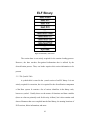
5.1 ELF Preliminaries ....................................................................................................59
5.1.1 Binary Layout ...................................................................................................59
5.1.2 The Symbol Table .............................................................................................61
5.1.3 Relocations ........................................................................................................62
5.2 Implementation ........................................................................................................63
5.3 Analysis....................................................................................................................67
5.3.1 Performance Impact ..........................................................................................68
5.3.2 Code Size Impact ..............................................................................................70
6. A Hybrid Technique ......................................................................................................71
6.1 Replication ...............................................................................................................73
6.2 Discussion ................................................................................................................74
6.3 Summary ..................................................................................................................75
7. Hiding by Camouflage ...................................................................................................77
7.1 Implementation ........................................................................................................78
7.1.1 Application Layer Camouflage .........................................................................80
7.1.2 Network Layer Camouflage ..............................................................................84
7.2 Lessons Learned.......................................................................................................87
vi
7.3 SMTP Session Example ...........................................................................................93
7.4 Results ......................................................................................................................95
7.5 Costs and Future Work ............................................................................................96
7.6 Summary ..................................................................................................................97
8. Conclusions ....................................................................................................................99
8.1 The Four Aspects .....................................................................................................99
8.2 Future Work ...........................................................................................................100
Appendix A. Virtual Memory and Processor State in x86 ..............................................102
Appendix B. VMCS Fields ..............................................................................................112
References ........................................................................................................................118
vii
List of Tables
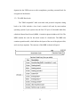
Table 1: Code size........................................................................................................40
Table 2: Padding entropy .............................................................................................50
Table 3: All combinations of two instructions with two transformations ...................52
Table 4: Entropy estimation of combined transformations..........................................54
Table 5: Minimal entropy estimation for combined transformations ..........................55
Table 6: Average code size increase (in kilobytes and %) ..........................................57
Table 7: Flags in Control Register 0 ..........................................................................109
Table 8: Flags in Control Register 4 ..........................................................................110
Table 9: Flags in EFER ..............................................................................................111
Table 10: Pin-Based VM Execution Controls field ...................................................114
Table 11: Primary Processor-Based VM Execution Controls field ...........................115
Table 12: Secondary Processor-Based VM Execution Controls field .......................116
viii
List of Figures
Figure 1: Exploitation threat model ...............................................................................6
Figure 2: The Bear operating system layers ................................................................19
Figure 3: Bootstrapping the hypervisor .......................................................................24
Figure 4: Illustration of the IBM-Compatible MBR and partition table......................25
Figure 5: Illustration of Extended Page Tables............................................................36
Figure 6: Function with two vacuous-padded variants ................................................46
Figure 7: Function layout after compiling and linking ................................................47
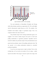
Figure 8: Benchmark results for vacuous code padding ..............................................56
Figure 9: ELF binary, section view..............................................................................61
Figure 10: Example binary and corresponding loader diversification .........................64
Figure 11: Control flow within same diversity unit .....................................................65
Figure 12: Control flow between two different diversity units....................................65
Figure 13: Hybrid diversity system..............................................................................71
Figure 14: Overview of system internals .....................................................................79
Figure 15: A packet’s path through the camouflager...................................................80
Figure 16: State machine representation of SMTP common path ...............................82
ix
List of Abstract Programs
Program 1: Enabling virtualization ..............................................................................30
Program 2: The hypervisor main loop .........................................................................31
Program 3: Handling memory violations .....................................................................38
Program 4: The padding transformation ......................................................................46
Program 5: The diversifying loading process ..............................................................67
x
Chapter 1: Overview
1.1 Problem
How can we increase attacker workload to reduce the incidence of
computer network attacks against critical infrastructure?
1.2 Hypothesis
A radical increase in non-determinism within operating systems can
require increased attacker time, effort, and failure, requiring increased
levels of attacker sophistication.
1.3 Approach
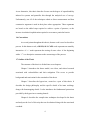
This thesis introduces non-determinism through four core mechanisms:
Gold-standard Refresh: Random refresh of potentially compromised
system components (e.g. microkernel, device drivers, etc) to remove an
adversary’s ability to persist over long durations; this also has the effect of
invalidating surveillance information associated with the operating system
signature, essential in determining the available vulnerabilities.
Compile-Time Diversity: Introduction of non-determinism into sourcecode at compile time to throttle vulnerability amplification, ensuring that
the same vulnerability cannot be used in multiple copies of the code.
Run-Time Diversity: Dynamic replication and randomization of code at
load time refresh to undermine reverse engineering and further invalidate
surveillance.
Camouflage: Disguising an operating system to appear as an alternative
1
system, with different vulnerabilities, to complicate system identification.
The combination of these techniques produces a new form of operating system
that increases attacker workload over multiple complementary dimensions
making it significantly more difficult to determine the vulnerabilities present on a
system, apply the same attack to multiple hosts, and establish a long-lived
presence on a system to achieve effects.
1.4 Contributions
The core contributions of this thesis are:
A novel, minimalist hypervisor capable of non-deterministically refreshing
and diversifying a hosted kernel; kernels may in turn use the same
techniques to refresh user code and potentially compromised device
drivers [1].
Compile-time techniques for introducing static diversity into operating
systems and user code [2].
Run-time techniques that add temporal diversity when combined with
refresh [3].
A hybrid approach that combines compile-time and run-time diversity
with replication to radically increase the degree of non-determinacy in
systems. This approach has modest overhead in performance and code size
[3].
Analytical models that quantify the level of non-determinism induced by
diversity [2, 3].
2
Application layer techniques that camouflage servers by modifying their
network traffic signatures [4].
These systems and techniques have been demonstrated in proof-of-concept
implementations and exemplars. The hypervisor has been implemented on multicore blade servers and Dell XPS workstations, supporting both a custom
microkernel and the BSD operating system. The compile-time techniques have
been implemented as a Clang compiler plugin and demonstrated by diversifying
the microkernel, an industrial strength web server (lighttpd), and the SPEC
benchmark suite. The run-time techniques have been incorporated into the
hypervisor and microkernel loader used to execute the microkernel and user
processes. Finally, the camouflage techniques have been used to circumvent
common network scanners, such as nmap [5] and Nessus [6], disguising a
Microsoft Exchange running on Windows 2008 Server as Sendmail running on
Linux 2.6.
1.5 Metrics and Analysis
Unfortunately, it is not practical to directly assess the increase in attacker
workload, as it is dependent on a number of subjective factors that include:
The available manpower and level of expertise of the attacker.
The creativity of the attacker.
The type and level of vulnerability of the target system.
The availability of multiple access paths, e.g. remote exploits, privilege
escalations, supply chain access, RF paths, etc.
3
As an alternative, this thesis therefore focuses on the degree of unpredictability
induced in systems and quantifies this through the analytical use of entropy.
Unfortunately, not all of the techniques admit to direct measurement and thus
constructive argument is used in their place where appropriate. These arguments
are based on the added steps required to achieve a point of presence, or the
increase in technical sophistication required to overcome a particular barrier.
1.6 Conventions
At several points throughout this thesis, abstract code is used to describe a
process. In this abstract code, a BOLD, ALL CAPS word represents an assembly
instruction. A “<-“ mark represents the storing of some value. A line beginning
with a “//” is a descriptive comment on the current stage of the process.
1.7 Outline of the Thesis
The structure of the thesis is divided into seven chapters:
Chapter 2 introduces the threat model, core ideas, and related research
associated with vulnerabilities and their mitigation. This serves to provide
background and motivation for the remainder of the thesis.
Chapter 3 describes the hypervisor, created as a part of this thesis. It
describes the design philosophy and the specific details of its inner workings,
along with bootstrapping details. It also introduces the fundamental protections
provided by the hypervisor to running kernels.
Chapter 4 describes the compile-time techniques developed in the thesis
and analyzes the level of diversity that can be obtained along with the associated
overhead.
4
Chapter 5 describes the run-time techniques incorporated into the loader
and integrated within the hypervisor and kernel. These techniques are contrasted
with the compile-time techniques in Chapter 4 and analysis quantifies the gain in
diversity and performance.
Chapter 6 develops a hybrid model that combines the methods in Chapters
4 and 5 and analyses the combined technique. Code replication is then added to
further increase non-determinism.
Chapter 7 introduces network camouflage and describes how it operates
on the system network stack.
Chapter 8 concludes the thesis, mapping out directions for future research
and lessons learned.
5
Chapter 2: Core Ideas and Related Work
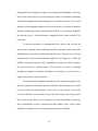
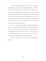
2.1 Threat Model
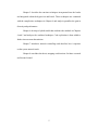
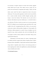
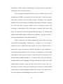
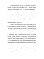
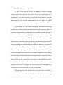
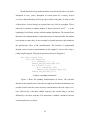
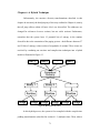
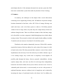
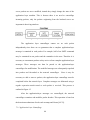
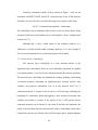
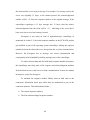
In order to provide context for the work presented in this thesis, it is useful
to provide a general threat model for network attacks involving remote control [7].
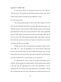
The model used here is presented in Figure 1 and combines typical activities
taken from a broad variety of attack classes. The threat may involve several steps
including surveillance to determine if a vulnerability exists [8], use of an
appropriate exploit or other access method to establish an implant [8], privilege
escalation where possible [9], removal of exploit artifacts, and hiding behavior
[10]. Surveillance may involve obtaining a copy of the targets binary code and
using reverse engineering [11,12] or fuzzing [13] to locate additional
vulnerabilities to facilitate a broad range of attack vectors, including return
oriented programming [14]. The implant then persists for a time sufficient enough
to carry out some malicious effect, obtain useful information, or propagate
intrusion to other systems.
Figure 1: Exploitation threat model.
6
Unlike the time to execute an exploit, the time spent in surveillance and
persistence may range from minutes to months or even years depending upon the
intended effect. Moreover, the presence of an intrusion may never be detected by
network defenses but instead may be recognized indirectly due to either a
deviation from expected behavior, or may be derived from intelligence sources.
2.2 Vulnerabilities and Vulnerability Amplification
The history of network intrusions, employing differing elements of the
model presented in Section 2.1, has been a continual arms race between defenders
and attackers: Vulnerabilities are revealed in hardware and software systems,
attackers develop exploit techniques to take advantage of them, eventually the
attacks are discovered and defenders develop appropriate protections and patches.
Subsequently, more advanced exploits that bypass the protections are introduced
and the cycle begins anew.
Buffer overflow attacks provide the most widely recognized example of
this pattern [15]. A complete description of the technique, along with how to
identify a vulnerability and exploit it, can be found in [16]. The essence of the
idea is to overrun a programming buffer with unexpected input so as to cause
installed software to make an unintended transfer of control; typically to
implanted attack code (often termed “shell code”). Since discovery of this form of
attack, a variety of solutions1 have been developed to specifically mitigate this
1
A survey of available protections, as well as more details on buffer overflow techniques, can be
found in [17].
7
particular form of vulnerability. Intel, for example, introduced the no-execute bit
for page tables, also known as Data Execution Prevention (DEP). This concept,
taken from the MULTICS [18] system, provides a mechanism that allows
operating system developers to ensure that memory is either writable or
executable, but never both simultaneously. There are not only hardware solutions
– software solutions have also been invented, such as runtime size checks for
buffers utilized on the stack [19].
Unfortunately, the advent of DEP and other solutions led to the
development of alternative exploitation techniques, which bypass the protection.
Some of the first attacks designed against DEP merely directed the running
process to call functions provided by the operating system to disable the
protections; they then proceeded with the classic buffer overflow [20]. These
functions seem insecure at first glance, but are actually useful: Some applications
require the same piece of memory to be both writable and executable. One such
application is a just-in-time compiler: It compiles (writes) a high-level
programming language to machine code and then executes it. Just like a binary
loaded from disk, the compiled code must be stored in memory at some location
before it is placed onto the processor for execution.
Eventually, attacks that bypass DEP execution prevention were
generalized. If a system function for disabling protections could be called, why
not call some other library function instead? This became known as the return-tolibc attack [21]. It then became clear that if an arbitrary library function could be
invoked, other chunks of pre-existing code could also be used. These chunks need
8
not necessarily be complete functions, but rather small assembly fragments
already loaded onto the system. These chunks, known as gadgets [22], can
perform some small amount of computation (add, multiply, compare), and then
redirect system control flow based on computed data written in the process
address space. The most prevalent opportunity to transfer control was provided by
the ret (return) assembly instruction available throughout operating system
images to return from functions. This instruction uses the system stack to
determine which address the processor should jump to, a convenient location to
store redirections. This form of exploit was named return-oriented programming
(ROP) [22]. Although it may not immediately appear particularly useful, a large
codebase such as the C programming library (libc), linked to every user process
on the system, contains a sufficient number of gadgets to be Turing-complete [23],
allowing any arbitrary program to be executed. A large set of gadgets is not even
required for many common exploitation tasks, such as the disabling DEP, and
even programs as small as /bin/true (without use of the linked C library) can be
exploited in this fashion [23].
Unfortunately, the fact that relatively few varieties of operating systems
are available world-wide, compared to the number of installed systems, amplifies
the impact of these vulnerabilities: A single exploit can often be employed against
a huge number of unpatched systems. Moreover, the increasing prevalence of
cloud computing tends to enhance this amplification by radically diminishing the
variety of installed system variants.
2.3 Stealth and Persistence
9
Once a vulnerability has been discovered and an exploit developed, it is
possible to establish a remote point-of-presence, similar to a remote shell. A
common next step is to remove the forensic trail associated with access by
deleting files, modifying registry keys, etc., and hide any on-host activity. This
job is often performed by a rootkit – a program delivered by the exploit and
operated unwittingly by the infected machine. One of the oldest stealth techniques
is to bundle, with the rootkit, programs that replace common system
administration programs [10]. For example, the ps program lists all processes
running on a system, but the rootkit’s version of ps would fail to report the
presence of the rootkit. This technique eventually gave way to returning false
values for system calls that ps would use to gather the list of processes, bypassing
the need for replacement programs [10].
Once a rootkit is resident on the system, how does it persist? If it exists
purely in volatile memory, such as a modification to the running kernel code, it
will be removed upon a system reboot. The rootkit thus must have some other
residence in non-volatile storage. The hard disk provides the oldest known
example [24], but some hardware contains non-volatile memory that can be
modified with proper system privileges [25]. To survive any kind of refresh like a
reboot without the system being exploited anew, the rootkit must utilize one of
these devices.
2.4 Reverse Engineering
It is possible that an attacker may have access to a copy of the source code
for some or all of a system, it might be open source code, or might be provided by
10
an insider. Alternatively, the point-of-presence established in Section 2.1 might
be used to extract a copy of the running binary code directly from memory.
Having obtained the source code, it is then possible to reverse engineer it
to discover vulnerabilities and develop additional exploits. Buffer overflows and
other memory corruption attacks require knowledge of the distance between the
vulnerable data and the interesting parts of the stack. Return-to-libc attacks
require knowledge of the location in memory of the desired functions. Returnoriented programming requires knowledge of desirable gadgets. All of this
information can be discovered either through either static analysis -- offline
disassembly and reverse engineering the addresses at rest -- or dynamic analysis -instrumenting and observing the code while it is running. This analysis can also
provide insights into how the attacker might best hide their tracks, or interrupt and
resume normal operation of the system via important addresses in the code. A
wide variety of tools are available to conduct this analysis, including simple
disassemblers like objdump [26] and complex tools such as IDA Pro [11].
2.5 Protection Mechanisms
Many of the fundamental concepts now used to protect operating systems
are derived from the engineering principals of separating concerns and
encapsulation embodied in the MULTICs operating system [18]. This resulted in
several innovations including the division of an operating system into layers, or
protected rings, through hardware mechanisms that separate user processes from
the system kernel and each other. MULTIC’s also included the concept of
read/write/execute protection bits on memory segments, where each segment
11
maintains independent access controls and a fault is generated if software violates
the protections. Read and write access controls subsequently became
commonplace in hardware platforms such as the Intel x86 processors. Execute
protection has only recently regained currency through the x86-64 platform via
the introduction of a no-execute bit into 64-bit page table entries [27].
Although techniques have been found to bypass basic protections on
occasion, their utility as an organizing principal and a first line of defense cannot
be overstated. With the advent of return-to-libc attacks and return-oriented
programming, the presence of basic protections allowed the development of
techniques to specifically target these advancements in exploitation independently.
For example, compiler-techniques were developed to mitigate return oriented
programming by scrubbing usable gadgets out of the assembly process [28-29].
The continual arms race between exploit and mitigation calls into question
the entire approach associated with detecting intrusions or reacting to discovery,
through sensors, patches, and defense tool rules. In this situation, the defender is
always forced to react to the attacker and takes few proactive steps to undermine
an attacker’s actions before they are known. Instead, this thesis proposes to focus
on increasing attacker workload by complicating each of the component activities
encapsulated in the thread model.
2.6 Non-Determinism and Diversity
Cohen [30] and Forrest et al [31] have discussed ideas for using nondeterminism to prevent exploitation. In addition, Forrest has implemented a basic
stack frame space randomizer which, while minimal, was sufficient to disrupt
12
many buffer overflow exploits. Unfortunately, no concrete metrics are provided to
quantify the level of effective diversity.
The most prominent approach that has evolved is Address Space Layout
Randomization (ASLR), developed by the Linux PaX team [32] and later used in
many other operating systems including variants of Windows. This technique
introduces diversity by randomly relocating the base address of libraries, program
text, stack, and heap, at runtime, though it does not attempt to perform any
reordering or randomization within these memory segments. This removes the
ability for attackers to statically pre-determine the address of functions and
gadgets used to build exploits or arbitrary code fragments – denying surveillance,
rather than eliminating the vulnerabilities themselves.
ASLR is believed to be effective against both return-to-libc attacks and
return-oriented programming. Unfortunately, a minimal level of entropy is
required to protect against brute-force attacks [33]. Early analytical work to
quantify the impact on attacker workload has already been conducted; it
concludes that approximately 16-bits of entropy, corresponding to 65,536 unique
code addresses within a process image, are required to protect against brute force
attacks within reasonable timeframes i.e. 20 minutes. There also exist methods to
eliminate address space randomness through techniques that bypass the ASLR
implementation altogether using specially crafted format strings [34]. It is
interesting to note that ASLR was developed before the advent of return-oriented
programming as a general mitigation against static analysis. This speaks well of
the general approach of introducing diversity to deny surveillance.
13
Other work has also been performed in the space of diversity: Instruction
Set Randomization encrypts the executable code and grants a level of entropy
equal to the strength of the encryption [35]. Unlike the research described here,
this approach requires architecture support for some form of emulation [36], or
virtualization [37]. The diversity approach described in this thesis has none of
these restrictions and can be strengthened by additional techniques including
memory encryption [7,38], hardware hiding [39], and nondeterministic refresh;
however, it does require access to source code.
Tanenbaum has used an alternative approach to protect kernel data
structures [40]. Unfortunately, his work uses compartmentalization and
modularization of code limited to microkernel designs. While this research
involves a microkernel, it targets more than just kernel data structures; the ideas
can also be applied to user processes and device drivers. Device drivers are
especially problematic, as they contain error rates up to seven times higher than
the rest of kernel code [41].
Several authors have examined the use of diversity to directly modify
binaries on disk. For example, Pappas et al [42] developed a tool that would
diversify compiled binaries by modifying instructions: this removes the
immediate vulnerability (while introducing new gadgets) and denies offline
surveillance, but would not protect against an attacker that successfully obtains a
copy of the diversified binary; the research described in this thesis would also
defend against such surveillance. Similarly, Kil et al [43] developed a tool to
diversify binaries by relocating segments and reordering within segments, but the
14
code within the segments is unchanged. This work has the same weakness as the
tool developed by Pappas et al.
Some researchers have examined diversity, not to deny surveillance, but to
specifically disrupt return-oriented programming. In an upcoming paper at the
2013 International Symposium on Code Generation and Optimization, Larsen et
al present a diversification scheme at the compiler level that modifies the
instruction generation algorithm to remove gadgets, entirely preventing their
emission by the compiler. This has no value in denying surveillance, and instead
only targets return-oriented programming. This thesis does not perform any
gadget removal: instead, it aims to increase the unpredictability of all addresses.
This disrupts the positioning of gadgets, denying surveillance, but does not itself
change the instruction stream or program semantics.
Other diversification techniques have been introduced that are similar to
the work described in Chapter 4 and 5. Kil et. al. include a similar method of
function reordering in their own binary rewriting tool [43]. The method described
in this thesis, on the other hand, implements this functionality directly in the
linker (for Chapter 4) and at runtime (for Chapter 5) to deny surveillance. kGuard
[44] uses a similar technique of padding the start of functions, an operation used
in this thesis and described in Chapter 4. However, they only do this to protect
and diversify the kernel, not user applications. Furthermore they use a NOP sled
to change address locations. The work described in Chapter 4 specifically uses
random data, so that any jump attempt will likely crash immediately. While
ASLR by default does not randomize within the text segment, this feature was
15
eventually introduced with the Code Islands technique in [45]. This utilizes
several similar features to our run-time diversity system; however, the work
described in Chapter 5 is not bound by the legacy requirements of the Linux
operating system and thus does not suffer the same performance penalties with
dynamic linking; it is also used to protect the operating system itself.
2.7 Camouflage
One method of surveillance is to use a network scanner, such as nmap [5]
or Nessus [6]. These scanners can detect which software and operating systems
are running on target machines, as well as their specific versions. This
fingerprinting effectively provides an attacker with a roadmap of how to exploit
the machine. This thesis presents a method for denying surveillance directly
through network camouflage.
Fingerprinting is possible by virtue of the differences in network- and
application-layer protocol implementations for different operating systems. The
protocol specifications typically leave many implementation details up to the
developer. This allows for multiple implementation strategies and ideas to be used
in alternative products. When these design details diverge between competing
systems, the differences can be observed by merely using the protocol. Nmap and
Nessus both exploit the differences in implementation details for their
fingerprinting process. For example, for operating system detection they have
databases specifying which details are expected on which system. By examining
the response to TCP/IP traffic, they discern which operating system the responses
16
must have originated from. Similar systems exist for application-layer protocols
in Nessus [46].
Since service detection is performed by examining implementation
differences, it is possible to deny surveillance by modifying these differences.
Early uses of this idea, implemented in Morph [47], were able to transparently
camouflage a system to appear as Windows 2000, OpenBSD, or Linux 2.4. The
concept has also been used in FreeBSD, which scrubs its fingerprint so that it is
not detectable by scanners [48]. Linux 2.4 provides a program called IP
Personality that allows it to take on alternative operating system characteristics
[49]. All of these packages focus on manipulating TCP/IP protocol details to
prevent operating system detection. Unlike these solutions, this thesis focuses on
denying surveillance of both the TCP/IP protocol, to prevent OS-level
fingerprinting, and the application layer, to prevent discovery of the specific
programs being run on the server.
17
Chapter 3: Gold-Standard Refresh
To explore the ideas non-deterministic refresh, code diversity, and
camouflage it is useful to consider how these techniques might form the basis for
a from-scratch operating system design. Current operating system designs have
sought to utilize a static base of trust and extend trust into software through
deliberate layering [50]. A wide variety of vulnerabilities have appeared that
undermine kernel security allowing attackers to implant code, hide, and persist at
the highest levels of privilege [51]. Furthermore, studies of open source code have
indicated that the number of vulnerabilities is directly correlated with the size of
the code base [52], indicating that there is substantial value in the intellectual
process of reducing the attack surface.
The approach described here assumes that adversaries will conduct
surveillance, will be successful in gaining access, and will persist undetected. To
mitigate the risks associated with remote control, the current kernel, user
processes, and device drivers are periodically discarded. This can be achieved
when they are momentarily not in use, through a collaborative program of
interruption, or just prior to the onset of a tactical operation. They are replaced by
new instances, bootstrapped in the background from read-only gold standards.
The cumulative effect of this change in design style is to increase attacker
workload by continually invalidating surveillance data and denying persistence
over time-scales consistent with tactical missions. Unlike other approaches to
computer security [53], no attempt is made to detect intrusions: instead, this
research focuses on continually validating, preserving, and re-establishing the
18
ability of a mission to proceed. The intent is to cause the attacker to take more
time, make more errors, and force attack actions outside the OODA loop of the
defender; effectively removing the threat without directly confronting it.
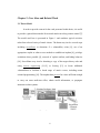
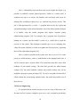
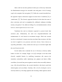
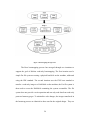
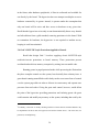
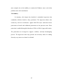
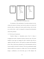
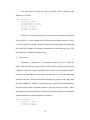
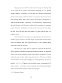
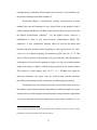
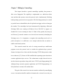
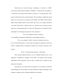
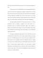
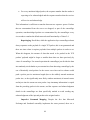
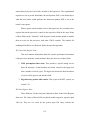
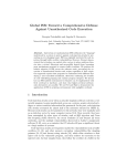
These concepts have been incorporated into a new, from-scratch operating
system design – Bear – which operates on 64-bit, x86 multi-core blade servers,
and Dell workstations. The full system is depicted in Figure 2 and is composed of
a minimalist micro-kernel with an associated hypervisor that shares code
extensively to explicitly reduce the attack surface. The micro-kernel also operates
independently on ARM M3, M4, A8, and A9 processors.
Figure 2: The Bear operating system layers.
The core functions of scheduling user processes and protecting them from
each other are handled by the micro-kernel [1]. All processes and layers are
hardened by strictly enforcing MULTICS-style read, write, and execute
protections [18] using 64-bit x86 address translation hardware. Similarly, the
hypervisor enforces these protections on kernels. This calculated reduction in
19
versatility is unlikely to impact military applications but explicitly removes
vulnerabilities associated with code execution from the heap or stack. All
potentially contaminated user processes, device drivers and services are executed
with user–level privileges and are strictly isolated from the micro-kernel via a
message-passing interface. The system task, executing with kernel privileges,
mediates between processes and the kernel to implement the interface. Unlike a
conventional rendezvous mechanism [54], this asynchronous, buffered design
provides a single uniform treatment of system calls, inter-process, and interprocessor communication. The interface also supports distributed computing
through an MPI-like [55] programming model that maps processes to processors
using a user level demon, rMP.
To prevent persistence in the micro-kernel, it is non-deterministically
refreshed from a gold-standard image in the trusted file store by the hypervisor
[56]. This store is currently realized through a read-only RAM-disk accessible
only from the kernel and hypervisor; however, it could alternatively be realized
via read-only memory (ROM) or via an out-of-band, write-enabled channel to
flash on new hardware. This minimalist hypervisor design supports only the
operations required to bootstrap a new micro-kernel and change its network
properties (e.g. IP & MAC address) so as to invalidate an adversary’s surveillance
data. It is significantly different from traditional hypervisors that aim to support a
general virtual machine execution environment [57-59], admits to considerable
code sharing with the microkernel, and represents a substantial reduction in the
system attack surface [1]. The PXE-boot based bootstrapping process
20
incorporated into the hypervisor applies diversifying transformations to each new
kernel. This ensures that every kernel is unique in terms of its addresses, throttling
vulnerability amplification and rendering prior surveillance obsolete. The current
running and bootstrapping instances of the micro-kernel are isolated in hardware
through extended page tables, implemented with Intel Vt-x extensions. Similarly,
the network driver is isolated through a mapping scheme based on Intel VT-d
extensions.
To prevent persistence in compromised device drivers and services, the
micro-kernel randomly and non-deterministically regenerates them from goldstandard images resident in a trusted read-only file store. This process is achieved
using the same diversity transformations applied by the hypervisor. Unlike the
MINIX re-incarnation process [54], regeneration is carried out without regard to
the perceived fault or infection status. User processes can also be refreshed
through pre-arranged or designated schedules; for example, every few hours, at
night, or just prior to a tactical mission.
The diversification techniques described in this research are applied every
time any component of the Bear system is refreshed: when the hypervisor reloads
a kernel or when the kernel reloads a device driver or user process. As a result,
even if an adversary were to obtain a copy of the entire binary code at any point in
time, and invest the effort to reverse engineer it to find vulnerabilities, by the time
those vulnerabilities could be exploited the entire address space of the system
would have changed and any existing persistent presence eliminated.
21
3.1 Hypervisor Design
The Bear includes a novel hypervisor has incorporates six core design goals:
1. Diskless, Read-only Bootstrapping.
2. Non-deterministic Kernel Refresh, Denying Persistence.
3. MULTICS-style Protections Applied to Kernels.
4. Processor State Protection.
5. Attack Surface Minimization.
6. Kernel Diversity, Denying Surveillance and Throttling Vulnerability
Amplification.
This chapter describes the realization of Goals 1 through 5; Goal 6, related
to diversity, is covered in Chapters 4 and 5. For now, it is important to simply
recognize that the hypervisor diversifies kernels and processes whenever they are
reloaded.
The hypervisor was developed to support only the core goals. Unlike
popular systems such as KVM, Xen, and VMWare, it is not designed to provide a
generic virtualization environment capable of supporting arbitrary systems.
Although the Bear micro-kernel has also been implemented on ARM architectures,
the hypervisor only operates on the x86-64 platform using its VT-x hardware
support for virtualization. This platform uses several structures and ideas for
processor control and memory protection, such as the CR0 and CR4 registers, real
mode, protected mode, long mode, segmentation, GDT and LDT. Appendix A
includes more information on these structures and their use, for those who lack
familiarity with the basic platforms.
22
The remainder of this chapter is devoted to the inner workings of the
hypervisor. These details operate collectively at the lowest level of the system to
realize the six core goals. The system bootstrap process is described first,
followed by the enabling of virtualization, and the hypervisor’s main loop. With
the groundwork of the hypervisor detailed this chapter then discusses how
virtualization can be used to protect kernels and other design considerations used
in creating the system.
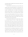
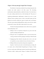
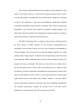
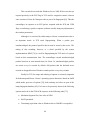
3.2 Goal 1: Diskless, Read-only Bootstrapping
The hypervisor bootstrap process takes the system from a powered-off
state to a running hypervisor. It must load all necessary system image files, set up
memory protections, and enter long mode -- a protected processor state required
to enforce memory protection. Most modern operating systems use long mode;
however, few enter this mode directly, instead operating initially in an
unprotected and vulnerable real mode during bootstrapping to support legacy
capabilities. Circumventing this legacy support with a from-scratch design not
only simplifies bootstrapping but also reduces the vulnerable time in real mode.
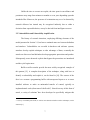
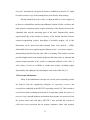
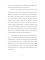
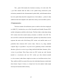
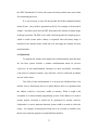
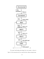
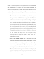
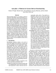
Figure 3 provides a simplified overview of the entire bootstrapping process. It
contains three concrete stages that incrementally built and protect the system:
MBR, Stage-1, and Stage-2 bootloaders. Each stage is circled, and lists the
specific tasks performed by the stage.
23
Figure 3: Bootstrapping the hypervisor.
The Bear bootstrapping process has emerged through two iterations to
support the goal of diskless read-only bootstrapping. The first iteration used a
simple Fat file system accessing a physical hard disk on the machine, addressed
using the IDE standard. The second iteration uses the PXE boot standard to
transfer a read-only image to a RAM-disk on the machine; the Fat file system is
then used to access the RAM-disk containing the system executables. The file
system does not provide a write operation and can only read data from read-only
protected memory pages. To minimalize code changes, the images transferred in
the bootstrap process are identical to those used in the original design. They are
24
deposited at the PXE-boot server after compilation, providing a natural hook for
encryption of the binaries.
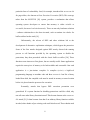
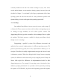
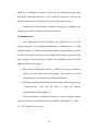
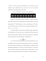
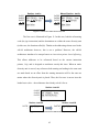
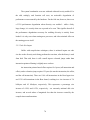
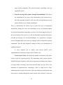
3.2.1 The MBR Bootloader
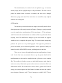
The "IBM compatible" label associated with personal computers dating
back to the 1980s includes a boot loader standard still used by most modern
operating systems: Upon system start, the first 512 bytes of a bootable hard disk,
called the Master Boot Record (MBR), is loaded at physical address 0x7c00. The
MBR contains the code for the initial section of a bootloader. The MBR also
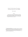
contains a partition table, which defines the layout of the rest of the physical disk,
and a two-byte signature. The structure of the MBR is shown in Figure 4.
Figure 4: Illustration of the IBM-compatible MBR and partition table.
25
The elements marked † in the partition table correspond to a CylinderHead-Sector method of addressing data on disk that are no longer used. Modern
systems, including Bear, instead use Logical Block Addressing (LBA) in which
512-byte sectors are laid out linearly on disk. For example, the 655th sector
would correspond to the data on disk ranging from bytes 655(512) to 656(512)-1.
Once the MBR is read into memory, the processor then begins execution
at address 0x7c00, the location of the MBR bootloader code. At this point, there is
no form of memory protection and the processor is in real mode.
The MBR bootloader is, of necessity, simple due to space constraints;
since it must share the MBR with the partition table, the maximum size of its code
is only 446 bytes. It first examines the partition table to discover the location of
the first partition, and then reads the first 512 bytes – containing the stage-1
bootloader – from that partition into memory. Unfortunately, before the stage-1
bootloader can be executed, some additional data must also be read from the disk:
a secondary structure called a disklabel (this is the standard disklabel used by
DragonFly BSD [60]) stored immediately following the stage-1 bootloader. The
disklabel is used to discover where the system images begin, as well as the
location and size of the final stage of the bootloader code – the stage-2 bootloader.
Once all of this data is read from disk, the stage-1 bootloader begins execution.
3.2.2 The Stage-1 Bootloader
The stage-1 bootloader examines the system RAM to build a map of the
available memory, sets up segmentation and paging, enters long mode to enforce
memory protection, and then passes control to the stage-2 bootloader. To build the
26
memory map, a BIOS call is invoked that returns a listing of available and
reserved memory regions. Diagnostic information can be displayed at this point
via a console that is enabled. Segmentation structures for the GDT and segment
registers are created. A read-only code segment is created for both privilege levels
0 and 3 that stretches from 0 to the end of memory. Two read-write data segments
are created in the same manner, and the segment selectors are initialized with
these values. Finally, following the enabling of segmentation, protected and long
mode are enabled: the low bit of CR0 is set, PAE mode for paging is enabled, and
bits 8 and 11 of the EFER MSR (IA-32e mode, allow NX bit) are enabled.
Although the boot loader has set the necessary bits for entering long mode,
it must also enable paging before long mode can be activated. To this end the first
two megabytes of physical memory are identity-mapped to virtual memory, so
that the physical and virtual addresses are equivalent. Finally, long mode is
enabled by setting the paging bit of CR0, reloading the GDT with a new
segmentation table (this table uses the same data, but with expanded sizes for the
larger address space), and enabling the 64-bit code segment. The system is now in
long mode, and the most basic requirements of modern operating systems have
been satisfied; However, the bootloader has more work to do before the
hypervisor can be started: Initially, the stage 1 bootloader enables the floatingpoint unit and vectorization units. Control is then passed to the stage-2 bootloader.
3.2.3 The Stage-2 Bootloader
The stage-2 bootloader is a much larger process that does not suffer from
the 512-byte size limitation due to presence of paging. Unlike the MBR and stage27
1 bootloader, it is written entirely in C and performs tasks that require more
complexity in code, which would result in a code fragments larger than 512 bytes.
For example, since the system has entered long mode, convenient calls to the
BIOS for basic tasks such as reading data from the disk and printing diagnostic
messages can no longer be used. Thus, basic drivers for disk access and printing
to the VGA memory must be included within this stage.
The stage-2 bootloader initially augments the already-paged memory:
increasing the identity-mapped paged memory from the first two megabytes of
system memory up to the first 12 megabytes, so that the hypervisor is guaranteed
to fit when loaded. It then utilizes a basic IDE disk driver to read the hypervisor's
ELF binary from the file system defined by the disklabel. Finally, the hypervisor's
ELF structure is analyzed and checked by a minimal ELF loader. This loader
performs no protection, relocation, or other complex tasks associated with normal
user program loaders. Instead, it merely verifies the file for validity and loads the
listed program headers. Once loaded, control passes to the entry point listed in the
hypervisor binary. At this point, the boot process has completed.
Originally, the stage-2 bootloader also set up and handled a table of
system interrupts. This functionality was eventually deemed unnecessary, and
removed.
3.2.4 PXE Boot
The bootstrapping system described by Figure 3 is built upon a network
boot protocol, called PXE boot, which runs before the MBR boot loader. The
protocol downloads the image of a program named MEMDISK from a networked
28
server [61]. This program transfers over the network a hard disk image containing
the Bear operating system, which mirrors the structure and filesystem of the
original physical hard disk. The MEMDISK program then copies the first 512
bytes of this disk image to physical address 0x7c00, just as the BIOS would do
with the original physical hard disk. Then, the system begins executing the code
or data as it originally did with the physical hard disk. The post-MEMDISK
environment is indistinguishable to the environment seen by the bootloader
without using network boot. However, any BIOS calls to disk reads are instead
redirected by MEMDISK to the hard disk image in memory.
3.3 Goal 2: Kernel Refresh, Denying Persistence
This section describes the hardware control and structures associated with
virtualization on the Intel x86-64 platform and how these are used by the Bear
hypervisor to operate virtual machines and perform kernel refresh. This feature set
is commonly called Vt-x and the features are named in the Intel manual as VMX.
Unlike many x86 features, Vt-x is not shared between Intel and AMD processors
– AMD has its own hardware feature set for virtualization, called SVM. Bear
initially targets Intel processors, and thus uses Intel VMX.
3.3.1 Enabling Virtualization
The virtualization feature set is controlled by the VMXE bit of the CR4
control register. To activate virtualization, this bit must be set; however, there are
several subtleties that must also be observed. The abstract code in Program 1
describes the complete process.
29
// Check if VMX is available on this processor.
CPUID
Bit 5 in ECX set?
No -> Fail
// The BIOS can disable VMX. Test this, and enable VMX
// if it is not locked out.
Read MSR 0x3a
Bit 0 set, bit 2 cleared?
Yes -> Fail
Bit 0 set, bit 2 set?
Proceed
Bit 0 cleared, bit 2 cleared?
Set bits 0 and 2
// The VMXE bit must be enabled.
Set VMXE in CR4
// CR0 and CR4 must have specific bits set or cleared.
// Test that the values are what are needed for VMX.
tmp <- Read MSR 0x486
tmp = (CR0 AND tmp) XOR tmp
Is tmp 0?
No -> Fail
tmp <- Read MSR 0x487
tmp = (CR4 AND tmp) XOR tmp
Is tmp 0?
No -> Fail
// The processor uses a 4096-byte, page-aligned region
// of memory for storing information.
Allocate 4096-byte region of memory: VMX-Region
Zero VMX-Region
VMX-Region[0:29] <- MSR 0x480
VMXON VMX-Region
Program 1: Enabling virtualization.
On conclusion of this process, the processor is capable of utilizing
virtualization. This includes launching, swapping, and resuming virtual machines.
In this process, the hypervisor is called the host and the virtual machines it
controls are called the guests. Launching or resuming a guest is called a VM entry,
and control being passed back to the hypervisor is called a VM exit.
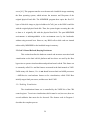
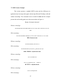
3.3.2 The Hypervisor Main Loop
30
Once virtualization is enabled through the process in section 3.3.1, the
hypervisor is ready to launch and control the Bear microkernel. Program 2
describes the basic operation of the hypervisor. It consists of a simple loop that
repeatedly creates a virtual machine, bootstraps the microkernel on a virtual
machine from the read-only file store, waits for a preemption time, and nondeterministically discards the kernel.
// Initialize VMCS Region
START:
Allocate 4096-byte region of memory: VMCS
Zero VMCS
VMCLEAR VMCS
VMPTRLD VMCS
// Controlling parameters for the kernel are then set.
// These include a preemption timer, control register
// state, instruction pointer, and other values.
VMWRITE some-parameter
VMWRITE other-parameter
...
Load kernel from gold standard read-only source
Apply diversification
Save hypervisor register state
// Begin execution of virtual machine
VMLAUNCH VMCS
... virtual machine execution proceeds ...
... Preemption timer interrupt!
Save virtual machine register state
Restore hypervisor register state
Time for refresh?
-> Throw kernel away, goto START
Save hypervisor register state
Restore virtual machine register state
VMRESUME VMCS
Program 2: The hypervisor main loop.
A hypervisor controls its guests through a block of memory called the
Virtual Machine Control Structure (VMCS). This is a four-kilobyte, page-aligned
block of memory, one per logical virtual machine that the hypervisor executes.
The VMCS contains all of the parameters associated with the guest that are
31
manipulated in Program 2, including how the virtual machine might automatically
be interrupted so as to pass control passed back to the hypervisor. There are a
large number of parameters that can be stored in this structure, not all of which
are used by the Bear system. The parameters used by the Bear system are listed
and described in Appendix B; a complete listing can be found in [27].
In addition to the steps described in Program 2, there are several other
necessary steps associated with bootstrapping a virtual machine. These include
determining default and supported values for various VMCS fields; however,
these are generally part of the initialization steps and not actively performed
during the loading and managing of virtual machines and have no direct bearing
on the project goals.
Recall that Program 2 refreshes the kernel from the RAM-disk
corresponding to the gold-standard, read-only source to deny persistence. The
read-only status of the disk is enforced by the hypervisor but could also be
realized through a hardware back-channel to allow updates. This refresh-fromstandard process ensures that if a rootkit were to persist in the kernel’s memory it
will be flushed out of the system. By utilizing the read-only source, rootkits lose
that avenue for persistence.
Although not yet described, it is valuable to understand the hook provided
by Program 2 for applying the diversity ideas (Goal 6) that will emerge in later
chapters: During the bootstrapping of a new kernel, the hypervisor uses an ELF
loader that incorporates the ideas presented in Chapters 4 and 5.
3.3.3 Kernel Environment
32
The hypervisor initializes each kernel in an environment that acts as if a
bootloader had initialized it. This environment mimics, in the kernel’s memory
space, all the normal attributes expected by a bootloader. System memory is
placed in the same map; segmentation registers and paging are set up in the same
manner (though diversity is added); long mode is enabled. Control registers are
made to mimic those on the system. The parameter values used by the hypervisor
are read and are set as those of the guest, the only change being that virtualization
is disabled for the guest. Control register modification outside of these values is
rendered impossible (see section 3.4.2).
The address space given to each guest mimics that given to the hypervisor
by the bootloader, a 256-megabyte chunk of memory is allocated for each guest.
This memory is redirected it so that the guest operates on physical addresses from
zero to 256 MB (see section 3.4.1 for more details on this process). A BIOS
memory map is placed at the normal bootloader location, marking the BIOS areas
as unavailable and the rest of the space as available for system use. Unlike the
hypervisor bootloader however, the hypervisor employs a sophisticated and fullfeatured ELF loader. This enables the hypervisor to apply diversity to the kernel’s
ELF binary, both the kernel code and data scattered throughout its address space.
For more information on this process and the details of the scattering, see chapters
4 and 5.
Some spaces external to the guests 256-megabyte chunk are redirected
into the kernel memory space. The VGA memory used by the console is placed in
its normal physical location. Any memory for the network card and, theoretically
33
in the future, other hardware peripherals, is likewise redirected and available for
use directly by the kernel. The hypervisor does not attempt to multiplex access to
hardware contested by its guests: instead, it operates under the assumption that
only one kernel will be active and have access to hardware at any given time.
Recall that the hypervisor exists only to non-deterministically throw away kernels
and refresh them from a gold standard, removing persistence in the kernel. With
no contention for hardware, the hypervisor is not required to mediate access,
keeping its code base minimal2.
3.4 Goal 3: MULTICS-style Protections Applied to Kernels
Recall that design Goal 3 involves applying classic MULTICS-style
read/write/execute protections to kernel memory. These protections prevent
accidental and malicious memory corruption by writing into executable code.
Running guests in paged protected mode while preserving the illusion that
they have complete control over the system, has classically been a thorny issue. A
guest kernel running unmodified would clearly need to exert some form of control
over the system page tables in order to allocate its own memory and separate user
processes from each other. Giving the guest total control, however, would defeat
the point of the hypervisor providing protections and isolating guests: the guest
could examine and modify any memory on the system, including that used by the
2
Eventually, some form of validity checking with how a kernel interacts with the hardware may
be implemented. If this is done, the hypervisor will need to mediate access – but in this case, for
protection, not multiplexing.
34
hypervisor to control the guest. The hypervisor would then be unable to protect
kernels in the same fashion as kernels protect user processes.
Past solutions have centered on shadow page tables, where the guest
kernel is unable to actually access the page tables. The hypervisor keeps a
mapping of virtual memory as seen by the guest and its correct translation to
physical memory. Any attempt to modify CR3 or the page tables would cause a
VM exit, and the hypervisor would then handle the modification instead after
checking that it was acceptable. Any page fault would similarly be forwarded to
the hypervisor, which would need to service the interrupt. This process is slow
and puts the burden for checking whether a modification is benign (a process
switch) or malicious (making hypervisor memory accessible to the kernel) onto
the hypervisor. It also significantly increases the complexity of the hypervisor,
which then needs to incorporate knowledge of how to deal with the memory
management systems of each guest kernel that might need to run.
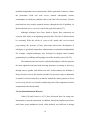
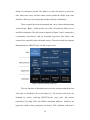
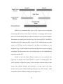
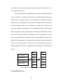
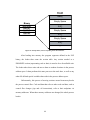
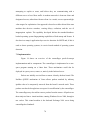
To deal with these issues, Intel released the Extended Page Table system.
This is a form of nesting where the guest has complete control over the classic
page table structure. The hypervisor provides an extra layer of address translation,
after the normal page tables, which is completely transparent to the guest
operating system. This allows a hypervisor to manage physical memory without
the overhead of shadow page tables while also giving the guest the illusion of
total physical memory access. A diagram of the resulting translation system can
be seen in Figure 5.
35
Figure 5: Illustration of Extended Page Tables.
Addresses are translated from guest virtual to guest physical using the
normal page table structure of the kernel. Afterward, a second page table structure
takes over which translates the guest physical address to its true physical address.
This structure is rooted by the Extended Page Table Pointer (EPTP). The EPTP is
defined in the VMCS, and is the EPT version of CR3. Much like the rest of the
system, an EPT page can be configured to be either four kilobytes or two
megabytes large, with the length of translation and page table structures changing
accordingly. The Bear system uses a four kilobyte page size for both the normal
page tables and the EPT.
Similar to how the kernel allocates memory for user processes, the
hypervisor can decide which system memory it exposes to running guests. This
choice generally excludes the memory of itself and other virtual machines on the
system, thus offering isolation and protection. A kernel cannot view other
memory on the system without modifying the hypervisor’s EPT structure, which
it cannot do without somehow breaking into the hypervisor.
36
While EPT has vastly simplified hypervisor logic, it comes with another
benefit – built-in MULTICS protections. EPT, just like the normal page tables,
allows the hypervisor to control which among read/write/execute permissions are
allowed for a given memory page. With the desired read/write/execute
permissions for memory segments set in the ELF binary for the kernel, these
MULTICS-style protections can be applied to the kernel, just as the kernel applies
them to its own running processes.
The Bear hypervisor configures EPT to provide these controls on kernel
code and data, learning from the kernel’s ELF binary which pages should be
protected to what degree. If there were no hypervisor, an exploit with kernel-level
access could modify the page tables to perform these operations at will. With the
addition of the hypervisor, however, any attempt to patch read-only kernel
memory or execute code located in a data region will result in a VM exit, at which
point the hypervisor can take appropriate action. Hypervisor memory is
inaccessible from the guest; using EPT, it does not even need to be mapped into
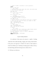
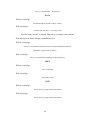
the guest’s address space. The abstract code for the hypervisor is thus augmented
as shown in Program 3.
37
// Begin execution of virtual machine
VMLAUNCH VMCS
... virtual machine execution proceeds ...
... EPT violation interrupt!
Save virtual machine register state
Restore hypervisor register state
// Take appropriate action. One possibility:
Log violation
Put kernel in background; accepts no new connections.
// Start a new kernel to handle new clients.
Goto START
// Restore the bad kernel on an unused processor.
Restore virtual machine register state
VMRESUME VMCS
Program 3: Handling memory violations.
The mechanism whereby a hypervisor might spin down a kernel with
outstanding connections until their completion, while spinning up a new goldstandard kernel for new connections, is explored in [56].
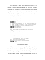
3.5 Goal 4: Processor State Protection
The intent of protecting the processor state is to prevent successful
exploits from performing modifications that would assist with stealth and
persistence. By virtue of adding another layer of hardware controls to the system,
hypervisors can provide protections to kernels that were previously impossible.
The ability to provide MULTICS-style protections has already been discussed,
but there are also additional mechanisms available to protect the processors
critical data structures. As these structures are often used by rootkits to aid in
stealth, protections on them can mitigate fundamental attacks against memory
protection. For example, consider the “CR0 trick” [10] used to bypass system
memory protections: The x86 architecture contains a flag in CR0 which, if cleared,
allows kernel-level code to write to any region of memory, even write-protected
memory. Since kernel-level code can modify CR0, any malicious code that wishes
38
to write to read-only memory need only clear the WP bit, perform the desired
writes, and reset the bit once more, entirely bypassing any form of writeprotection that has been set in the segment registers or page tables.
With hypervisor protections on the control registers, this attack can be
eliminated. Using specific fields in the VMCS (see Appendix B for more details
on these fields: the guest/host mask and read shadow), the hypervisor can set
this bit to a static value that a kernel cannot change. Then, a malicious attempt to
clear the bit will cause a VMexit, preventing undesired writes to read-only
memory3.
Unfortunately, these protections are not general-purpose in nature; many
operating systems, including the Bear bootloader, utilize write protection bypass
feature in their own code. Thus, to properly utilize these protections, the kernel
must be designed with the inability to bypass the restrictions in mind. Even if the
hypervisor enforces the condition that code to disable the protections was only to
be run within a specific function, malicious code could always return to that
function in a return-to-libc style attack, and then proceed. To ensure complete
write protection within kernels, the ability to bypass it at all must be removed. For
the Bear system, any possibility of disabling these write protections has been
3
It’s worth remembering that there are other ways to bypass write protections in the Intel system,
not just the CR0 trick. For example, the page table entries could be modified, by setting the
writable bits in the individual entry or creating a whole new page structure. Both of these can also
be controlled by the hypervisor though: either through use of EPT in the former or both EPT and
the CR3 controls in the latter.
39
removed – with the ability completely out of the kernel’s hand, any such returnto-libc style attack is taken off the table.
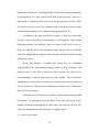
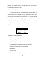
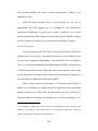
3.6 Attack Surface Minimization
The Bear system has been designed to minimize the attack surface by
extensively sharing code between the hypervisor and microkernel. Recall that a
survey of open source code discovered approximately 0.16 errors per thousand
lines of code in open source software [52], making the reduction of the attack size
a laudable goal for reducing vulnerabilities. Table 1 shows the current number of
unique lines of code in each component of the Bear system, as well as shared lines
of code.
Table 1: Code size.
Component
Lines of Code
Hypervisor
Kernel
Shared
1,788
2,335
5,062
The shared code includes the following:
Basic data structures (queue, hash table, etc.).
Interrupts handling
C-callable wrappers around basic assembler instructions.
Virtual memory subsystem, including allocation and freeing.
Disk access (including RAM disk) and filesystem.
System timer.
The ELF loader.
Process scheduler (schedules both user processes and virtual machines).
40
3.7 Supporting Legacy Operating Systems
A future research project involves the running of different operating
systems on the Bear hypervisor. This work is still in its vestigial stages and is
experimental, as the Bear hypervisor was originally designed solely to run the
Bear kernel. The first operating system that has been run on Bear is NetBSD
version 6.0.1.
Unlike running the Bear kernel, for NetBSD the hypervisor does not
perform any of the boot loader operations that the kernel expects to have been
performed. Segmentation and long mode are not enabled; instead, the guest is
started in real mode as if the system had just been booted – though a memory map
is provided as if performed by BIOS call. The system BIOS memory is copied
into the address space of the guest, so the guest may directly perform any BIOS
calls that it might need without hypervisor interference; otherwise, the hypervisor
would need to emulate a large number of complex BIOS routines.
Multiprocessing is not supported: while the ACPI region of the BIOS memory
reports that multiple processing cores are available, NetBSD has been compiled
and passed flags to disable this behavior and instead run on a single core, without
using ACPI at all. The current status of the project is that NetBSD successfully
boots, but does not start a shell due to lack of a root file system -- Bear no longer
supports a physical disk. To mitigate this involves porting NFS and pointing it to
an NFS share across the network to act as its root filesystem.
This work has only been possible due to the open nature of NetBSD; a
similar attempt to virtualize Microsoft Windows would likely prove to be much
41
more complex due to the inability to examine the Windows source code when
problems arise with virtualization.
3.8 Summary
In summary, this chapter has described a minimalist hypervisor that
continually refreshes kernels to deny persistence. The hypervisor shares code
extensively with the microkernel, applies MULTICs-style read/write/execute
protections to kernels and additional protections on the processor state. Write
protection is enabled through the hardware NX-bit in X86-64 page table entries.
The protections are leveraged to support a diskless, real-only bootstrapping
process. The hypervisor main loop provides the necessary hooks for adding
diversity every time a new kernel is refreshed.
42
Chapter 4: Diversity through Compile-Time Techniques
Diversification is the primary mechanism for preventing unexpected code
execution and similar exploits in the Bear system. The diversifying
transformations nondeterministically scramble the locations of code and data on
the system, making exploits that rely on this knowledge fail. The process of
introducing nondeterministic modifications to binaries also serves to create
differences between running versions of code on networked systems and thus
throttle the vulnerability amplification aspect of networks such as the Internet.
With each system running something different, attackers must craft new exploits
to target specific systems, rather than a single exploit for every system.
The Bear diversifying transformations seek to achieve four key properties
in the resulting binary codes:
1. Shifting all code out of position to disrupt the entry points for all code
segments, including unanticipated ones.
2. Placing all code in an unpredictable location to prevent an attack from
resuming to normal execution by jumping or returning to a known location.
3. Changing jump offsets within all code paths, such as if/else, switch, and
for-loop blocks, to remove similarities between all variants of a binary.
4. Shifting of all data out of position to disrupt direct manipulation.
Properties #1 and #2 prevent code execution that hijack pre-existing code
on a system, such as Return-Oriented Programming [14]. Property #2 denies
persistence on the system, disallowing an attacker from achieving a hidden pointof-presence within a running system. Property #3 enhances diversity beyond
43
ASLR [32], extending the entropy to logical blocks within the program rather
than simply individual functions or ELF segments. Property #4 removes the
ability to designate control or plant code in pre-existing data structures.
Compile-time diversification is performed through two operations: the
padding transformation and the ordering transformation.
4.1 Implementation
The compile-time diversity techniques are introduced as part of the
compiler toolchain. The padding transformation is implemented as a Clang
compiler plugin [62], and the ordering transformation is implemented as a patch
to GNU Gold, a linker that is part of the standard GNU Binutils package [26] on
Linux systems. To add diversity to a binary, the compilation process must be
slightly modified in two stages:
1. Before normal compilation with the C compiler (such as gcc), the source
files must be diversified via the clang plugin. This represents as a precompilation pass, and applies the padding transformation.
2. The linker requires an additional flag passed as part of the linking process:
“--randomize-text”. This tells the linker to apply the ordering
transformation to the final output.
The resulting binary is identical in function to a binary compiled without
diversity, but has been nondeterministically modified to satisfy goals 1, 2, and 3.
4.1.1 The Padding Transformation
44
Recall that the diversity transformations are motivated by three core goals:
disruption of entry points, disruption of return points for resuming normal
execution, and modification of all jump offsets within code paths. To achieve each
of these ideas, s bits of entropy are injected into every block in a program. This is
achieved by inserting a random number of bytes, between 0 and 2s – 1, at the
beginning of each block, using a uniform random distribution. The inserted bytes
themselves are random numbers. Jump instructions are inserted before the random
byte stream to ensure they are not executed by normal operation; this minimizes
the performance effect of the transformation. The insertion is implemented
through source-to-source transformation on the original C source code using a
Clang compiler plug-in. The plug-in operates as shown in Program 4.
For each source file:
For each function:
n <- random(0, 2s – 1)
insert_asm_string(“jmp 1f”)
for i from 0 to n:
b <- random(0, 255)
insert_asm_string(“.byte b”)
insert_asm_string(“1:”)
Program 4: The padding transformation.
Figure 6 shows the padding transformation in action. The left-most
function is the original source code; the two right-most functions demonstrate two
possible results from the source-to-source transformation: the first using a twobyte, followed by a four-byte random sequence; the second using a one-byte
followed by a two-byte sequence. This represents a “random” amount of vacuous
code inserted into every block.
45
void fn() {
if(var) {
…
}
….
}
void fn() {
jmp 1f
0x63 0x4F
1:
if(var) {
jmp 1f:
0x27 0x15
0xCA 0xD5
1:
…
}
….
}
void fn() {
jmp 1f
0xA9
1:
if(var) {
jmp 1f:
0x02 0x24
1:
…
}
….
}
Figure 6: Function with two vacuous-padded variants.
In consequence of this transformation, if an attacker attempts to use preexisting code present in the binary, based on static analysis, the execution will
incorrectly jump to a random prior location, typically causing a crash. On some
rare occasions where a crash is not triggered, an unexpected non-deterministic
action will be performed.
4.1.2 The Ordering Transformation
Generally, linking is a deterministic process. Even if a binary is
recompiled, the location of functions in memory remains the same. This can be
modified to some degree by changing the order in which the object files are
supplied to the linker, but this is also typically an automatic and deterministic
process. There is little reason, performance-wise, for this determinism, and every
reason to modify it for the sake of diversity. The ordering transformation outputs
functions within the text segment in a random order. It has been implemented
through a modification to the Gold linker (part of GNU Binutils). The
46
transformation only operates on input sections of the object files marked as text
(ie. corresponding to code).
This transformation can be applied at the fine-grain of individual functions,
as shown in Figure 7, provided the object files are compiled with one function per
ELF section (i.e. using the -ffunction-sections flag on gcc-compatible compilers).
Alternatively, it can be applied at coarse-grain on complete object files, where the
location of the entire object file is randomized. A simple -Wl,--randomize-text
flag on the compiler command line for a gcc-compatible compiler will inform the
linker to apply the ordering transformation. This ordering transformation ensures
that even if an attacker learns the base address of the text segment, they will not
be able to exploit memory vulnerabilities discovered through static analysis of the
binary. The implementation is extremely simple: before the linker writes the text
sections to the output binary as normal, the array containing these sections is
randomly shuffled. The result of applying this transformation is demonstrated in
Figure 7.
plt
plt
int main() { ... }
_start
_start
void fn1() { ... }
main
fn1
void fn2() { ... }
fn1
fn3
void fn3() { ... }
fn2
main
fn3
fn2
Figure 7: Function layout after compiling and linking.
4.2 Quantifying Diversity
47
Each transformation injects a certain amount of nondeterminism. To
measure this amount, this research uses Shannon entropy. Shannon entropy is a
familiar concept: specifically, it measures the information content of a random
variable. Our diversifying transformations effectively inject measurable entropy
into running processes and their binary images. The amount of injected entropy
informs us to both the effective number of unique variants created by our
transformations, and the difficulty of using brute force to discover a specific
address of a piece of code or data. The random variable, in this case, is the
memory address of an arbitrary code fragment.
4.2.1 Entropy of the Padding Transformation
Since the linker by default lays functions directly back-to-back in the
program binary, the amount of entropy gained by the padding transformation is
not solely derived from the number of random bits s injected in each function.
Instead, the locational difference that any given code fragment could take is also
based on the number of blocks b in which bytes are placed earlier in the file. The
probability of a locational difference of a given magnitude is equivalent to the
probability of the rolling that magnitude on b s-sided dice. For large values of b,
the probability p can be approximated using a normal distribution with variance:
p = b(s2 -
Thus based on the definition of entropy on a normal distribution, the total
number of bits of entropy can be approximated by:
lg(2·π·e·p) / 2
This value only represents the entropy available to the very last instruction
in the binary; as one proceeds toward the top of the binary, the number of blocks
48
decreases, as does the entropy (as the distribution becomes less normalresembling with fewer dice rolled). However, when including the ordering
transformation, the terminating instruction in every function can potentially be the
last in the binary file, and thus the calculated value becomes substantially more
meaningful: now the entropy of each block is quantified, rather than the only the
final block.
To approximate padding entropy for discrete binaries, replace the term b
with the average number of blocks per function. Doing this, Table 2 presents this
level of entropy as a function of s and the corresponding number of unique
variants generated for three code exemplars: the Bear hypervisor, the Bear kernel,
and the open source web server lighttpd [63]. The hypervisor contains 3460
blocks (an average of 9.25 blocks per function), and the kernel 3833 (an average
of 12.44 blocks per function) at the time of measurement. Lighttpd contains 1629
blocks (an average of 4.59 blocks per function). Using these values, Table 2
presents the level of entropy as a function of s and the corresponding number of
unique variants generated. The first number in the table entries represents the
entropy for the whole program, and the second number in [brackets] represents
the entropy of an individual function in the program. The units of entropy are bits,
and the units of variants are merely the total number possible.
49
Table 2: Padding entropy
Maximum Bytes Inserted
Exemplar
8
16
64
256
Hypervisor
Entropy
9.12
[3.36]
10.13
[4.06]
12.13
[5.45]
14.13
[6.83]
Hypervisor
Variants
557 [10]
1,121 [17]
4,491 [43]
17,965
[114]
Kernel Entropy
9.20
[3.51]
10.20
[4.20]
12.21
[5.60]
14.21
[6.98]
Kernel Variants
586 [11]
1,180 [18]
4,727 [48]
18,908
[126]
Lighttpd Entropy
8.58
[3.01]
9.59 [3.71]
11.59
[5.09]
13.59
[6.48]
Lighttpd Variants
382 [8]
769 [13]
3,081 [34]
12,327 [89]
Clearly, as seen in data, standing alone the padding transformation is not a
particularly impressive source of diversity: even with up to 256 bytes of padding
inserted only 19,000 variants can be obtained – small in comparison to the size of
modern cloud computing environments. However, this represents a base level of
diversity that can be further enhanced in combination with other transformations.
As will be shown, this combination radically increases entropy.
4.2.2 Entropy of the Ordering Transformation
The level of entropy generated by the ordering transformation is
deceptively complex to calculate. Without loss of generality, consider any
arbitrary function F. There is a uniform probability of placing this function in any
location among the other functions. However, functions can have different sizes.
Imagine the case where every function has a size equal to a unique power of two,
such that one function has size 1, one has size 2, one has size 4, etc. In this
specific case, every possible reordering of functions produces a unique
50
transformation of function F. Thus, if there are n functions, there are 2n unique
transformations and n bits of entropy. This provides an upper bound on the
amount of entropy possible, but is not particularly instructive as it is extremely
unlikely that all functions would be uniquely and appropriately sized.
An alternative is to establish a practical lower bound. Assume instead that
all functions are of identical size4. With all functions the same size, function F
can now be placed in only one of n unique locations. Therefore, the number of
bits of entropy from this technique is equivalent to lg(n), where n equals the
number of functions in the binary. Consequently, the lower bound on the number
of variants is equivalent to the total number of functions. For the exemplars, the
hypervisor has 374 functions, the kernel 308, and the Lighttpd program 355. Thus,
the transformation introduces at least 8.55, 8.27 and 8.47 bits of entropy,
respectively. Again, this is not a particularly impressive level of randomness
when taken in isolation.
4.2.3 Joint Entropy of the Transformations
These two transformations do not produce independent probability
distributions; therefore, their entropies are not additive. This is straightforward to
illustrate: imagine the simple case where there are two instructions, I1 and I2, each
4
If the size of one of these functions is varied, it could only increase the number of potential
transformations. This is because the differently-sized function could appear either above the
chosen function F instead of a non-size-varied function, which results in an additional case. With
all functions the same size, you only need to consider the total number of functions placed above
F, not which specific functions are placed above it.
51
of which is one byte long. These instructions can be relocated, and each
instruction can be padded with up to one byte. In this case, all possible
combinations of the transformations yield Table 3.
Table 3: All combinations of two instructions with two transformations.
Position
1
2
3
4
Case 1
I1
I2
Case 2
Pad
I1
I2
Case 3
Pad
I1
Pad
I2
Case 4
I1
Pad
I2
Case 5
I2
I1
Case 6
Pad
I2
I1
Case 7
Pad
I2
Pad
I1
Case 8
I2
Pad
I1
Without loss of generality, examine instruction I1. It appears in the first
position 2/8th of the time; the second position 3/8th; the third position 2/8th; and the
fourth position 1/8th. This distribution for I1 has an overall entropy of 1.9056 bits;
this is less than the sum of the entropy of the two individual components: lg(2) +
D(2,2) = 1 + 1.5 = 2.5 bits.
To find an analytical expression for the combined entropy introduced by
the transformations, it is necessary to derive a distribution for the position within
the binary that any arbitrary instruction can take. Again, without loss of generality,
choose the instruction at the end of the binary. Its distribution is:
𝑝(𝑥) =
1
∑ 𝑝𝑖 (𝑥)
𝑛
𝑛
For n unique layouts generated by the ordering transformation, 𝑝𝑖 (𝑥) is
the distribution of the same instruction for that specific layout. For any individual
layout, the instruction’s distribution is normally distributed, as though only using
the padding transformation. Let h be the size of the fixed function F, z be the total
number of blocks contained in this function and all functions above it in this
layout, and s be the maximum number of inserted bytes. With these parameters:
52
𝑝𝑖 (𝑥) ~ 𝑛𝑜𝑟𝑚(ℎ +
𝑧(𝑠 − 1) 𝑧(𝑠 2 − 1)
,
)
2
12
Using the definition of entropy with these parameters results in the
following definition:
∞
1
𝐻 = ∫ ∑ 𝑝𝑖 (𝑥) × lg(∑ 𝑝𝑖 (𝑥)) 𝑑𝑥
𝑛
𝑛
𝑛
−∞
Unfortunately, as mentioned in the section on reordering functions, there
is a problem in that the maximum number of transformations, n is exponential in
the input parameters. In theory, its size is bounded by the size of the power set of
the available functions. Thus, to develop a practical estimate of the available
entropy, two simplifying assumptions are made:
Every function is the same length.
Every function has the same number of blocks.
Recall that the first assumption was employed to gain a lower bound for
the entropy associated with the ordering transformation; the second is similar and
associated with the padding transformation. When taken in combination, they
reduce the calculation of entropy to a problem with linear complexity. In addition,
rather than integrating from -∞ to ∞, the lower limit is set to 0: for a small
number of blocks, and therefore a small number of dice, the normal distribution is
a poor approximation. Since the binary begins at location 0 and only positive
address values are possible, no actual source of entropy is removed. This
represents a more accurate representation of total entropy for transformations
when used in combination.
53
To provide a practical estimate of the expected entropy and number of
variants, a function length is chosen equal to the average for the binary. Similarly,
the ratio of blocks to functions is chosen to be the average for the binary. Table 4
shows the resulting levels of entropy and number of variants as a function of s.
Table 4: Entropy estimation of combined transformations.
Maximum Bytes Inserted
Exemplar
8
16
64
256
Hypervisor
Entropy
17.10
17.50
18.47
20.00
Hypervisor
Variants
140,480
185,360
363,100
1,048,576
Kernel Entropy
16.24
16.60
17.57
19.11
Kernel Variants
77,307
99,273
194,860
565,690
Lighttpd Entropy
16.32
17.03
17.60
18.46
Lighttpd Variants
81,898
133,480
198,860
359,840
Note that the combined entropy is radically increased even though the
component transformations presented little apparent entropy individually. It is
also interesting to note that the Kernel entropy is less than the Lighttpd entropy
for s=8, 16, and 64; however, it is higher for s=256. This is because the Kernel
has a substantially higher number of blocks per function than Lighttpd; this
number begins to dominate the expression as the insertion size increases.
Although these results provide a practical assessment, it is also instructive
to consider the minimal case where the function size is set to 1, with 1 block per
function. This represents an extreme degenerate case, that is unlikely to occur in
practice but provides insight to the minimal level of entropy that can be expected
in practice. Table 5 shows the corresponding values as a function of s.
54
Table 5: Minimal entropy estimation for combined transformations.
Maximum Bytes Inserted
Exemplar
8
16
64
256
Hypervisor Entropy
10.75
11.67
13.61
15.59
Hypervisor Variants
1,722
3,259
12,503
49,324
Kernel Entropy
10.47
11.40
13.33
15.31
Kernel Variants
1,418
2,702
10,297
40,623
Lighttpd Entropy
10.68
11.60
13.53
15.51
Lighttpd Variants
1,635
3,904
11,847
46,850
4.3 Performance Impact
Injecting random bytes into the start of every function is not without
consequences, both in run-time performance and code size. To measure the
impact on the former, this research utilizes the SPEC CPU2006 benchmark suite
[64]. The benchmarks were executed on an Intel Core 2 Duo T-9600 system
running Linux 3.3.1. Initially, two baselines were generated: with and without the
-fno-align-functions and -fno-align-jumps compiler flags required to obtain the
full level of entropy in the injected code. Subsequently, the benchmarks were
transformed using the padding transformation, compiled, and executed using the
SPEC benchmarking harness. The benchmarks were executed at nice -20 to
minimize the effect of the Linux scheduler. To ensure the worst possible
performance characteristics of the transformation, the maximum amount of
vacuous code padding was generated at every insertion point. This intentionally
degrades the performance of the processor’s caches to provide an upper bound.
The results of the SPEC benchmark are shown in Figure 8.
55
Percent Penalty (Lower is Better)
20
18
16
14
12
10
8
6
4
2
0
Degradation
Total from -O2
Figure 8: Benchmark results for vacuous code padding.
The worst benchmarks are 400.perlbench, 445.gobmk, and 458.sjeng
which yield performance penalties up to approximately 16%. This varied slightly
with the aforementioned compiler flags (up to 18%). The remainder of the
benchmark results indicates roughly 5% performance impact. This is low
compared to related work, such as Larsen et al.
The performance impact for the ordering transformation appears to be
negligible. It was tested in isolation using the same process as used for the
padding transformation; no appreciable performance degradation could be
measured. In addition, the performance impact of the joint transformation was no
greater that then performance impact of the padding transformation alone. This
was expected, as the ordering transformation introduced no measurable
performance degradation.
For code size, the average increase is simple to calculate. The size of the
resulting binary will vary based on the number of bits of entropy s actually
injected in each block. The average size increase is equal to the average of the
56
uniform distribution for code insertion, multiplied by the number of insertion
points. As mentioned, the number of insertion points is equivalent to the number
of blocks, b. Thus, the size average size increase for a given binary is equal to sb /
2 bytes. For the exemplars, the average code size increase is shown in Table 6.
Table 6: Average code size increase (in kilobytes and %).
Maximum Bytes Inserted
Exemplar
8
16
64
256
Hypervisor
13.8 (.59%)
27.7 (1.2%)
110.7 (4.7%)
442.9 (18.8%)
Kernel
15.3 (.55%)
30.7 (1.1%)
122.7 (4.4%)
490.6 (17.7%)
Lighttpd
6.5 (.9%)
13.0 (1.8%)
52.1 (7.3%)
208.5 (29.2%)
4.4 Adoption Challenges
The compile-time transformations require a modification to the compiler
and linker, and recompilation of programs from source. This is an obstacle to
distribution on popular closed-source systems such as Microsoft Windows, but is
feasible on systems such as Linux distributions, or in closed clouds where a store
of available binaries can be cross-mounted and loaded at will.
The proliferation of stack-guarding patches for the GCC compiler proves
that such distribution of transparent security measures is possible in open source
systems. Currently, only source-based distributions could be protected in a
widespread fashion, but the transition to runtime-based diversification will
eliminate that weakness. Obviously, the diversification has already been applied
and is running on the system it has been designed for, namely the Bear system.
4.5. Summary
57
This chapter has described two core compile-time transformations that
non-deterministically add diversity to a program. In the worst case, where up to
256 bytes are added to every block, the code size increase ranges from
approximately 18 to 30% while the runtime overhead ranges from 5 to 18%. For
an extremely small operating system code base (less than 10,000 lines of code), at
least 40,000 variants are available, with potentially more than one million variants
attainable. Obviously, as the code size increases, the potential for variability
increases commensurately.
58
Chapter 5: Diversity through Runtime Techniques
While a considerable amount of entropy can be injected using the
compile-time techniques, it is not sufficient. Recall that 16 bits of entropy were
experimentally determined as a minimum for protection [33]. The compile-time
techniques reach around 20 bits for the hypervisor, which is too close to the
minimum for comfort. Furthermore, the compile-time techniques have the sideeffect of a non-trivial performance penalty and file size increase. These shortfalls
of the compile-time techniques are addressable with the run-time techniques
presented in this chapter. The goals of the runtime diversity system are as follows:
Significantly increase the level of injected entropy.
Eliminate code size increases and remove performance penalties.
Add entropy without requiring source file modifications.
Transparently diversify any process running on the Bear system.
Work identically for diversifying kernels and user processes.
Diversify both code elements and data elements of a program.
The runtime diversity system developed here satisfies all of these goals.
5.1. ELF Preliminaries
Bear uses the Executable and Linkable Format (ELF) to store binary code
and data of programs in files. The full details of this format can be read in [62].
This section discusses the basics of the format and a small number of features
specifically used by the Bear system.
5.1.1 Binary Layout
59
An ELF file begins with a header placed at the start of the file. It then
contains either a program header or a section header, or both. If it contains a
program header then the file is an executable binary; the program header defines
segments. These segments describe the file addresses and corresponding memory
addresses of data that should be loaded into memory at program execution time
and their read/write/execute permissions. In general, the program header and its
defined segments describe how the loader should construct the binary image of
the process and begin execution. These segments do not merely define the code
within the binary: they can also describe the permissions that the stack, heap, and
other arbitrary elements will utilize.
There is a parallel view of the contents of the ELF binary: that defined by
the section header. The header defines sections, which contextually describes the
blocks stored within the binary. Sections put high-level meaning to the low-level
data blocks. One major class of sections is PROGBITS (code and data used as
part of the running process image); these include the process code (section
named .text) and pre-initialized global data (section named .data). Sections also
include metadata and other notes and comments, two of which are described in
more detail below. Figure 9 shows an example ELF binary from the view of the
section header, with several text sections and associated metadata sections.
60
ELF Binary
.text.main
.text.fn1
.text.fn2
.text.fn3
…
.rela.text.main
.rela.text.fn1
.rela.text.fn2
.rela.text.fn3
…
.symtab
Figure 9: ELF binary, section view.
The section data is not strictly required for the runtime loading process.
However, the data encodes fine-grained information that is utilized by the
diversification process. Thus, our loader requires this section information to be
present.
5.1.2 The Symbol Table
A symbol table is stored in the .symtab section of an ELF binary. It is not
strictly required for execution, but it is required for the diversification component
of the Bear system. It contains a list of various identifiers in the binary code,
known as symbols. Usually these are the names of functions and data variables
(these are what are primarily used for diversity in Bear), but it also contains such
data as filenames that were compiled into the final binary, the starting locations of
ELF sections, linker information, and more.
61
The table itself is merely an array of symbols. Each symbol has the
following C structure:
struct Elf64_Sym {
uint32_t st_name;
unsigned char st_info;
unsigned char st_other;
uint16_t st_shndx;
uint64_t st_value;
uint64_t st_size;
};
The field st_name is an offset into a string table, providing a string name
for the symbol. st_shndx contains the ELF section that a symbol resides in, if any.
st_value contains the symbol’s location in memory: for functions or data elements,
this would be its address; for arbitrary information, it could take any value. The
remainder of the fields are unused by Bear.
5.1.3 Relocations
Relocation is the process of connecting symbol references within the
binary code with their associated symbols. If the compiler or linker must output an
address of a function or data element that does not have a well-defined location in
memory, it instead outputs a stub value (normally all zeros) – the aforementioned
symbolic reference. The run-time loader must then fix up these stub values with
the correct addresses, which are contained in the symbol table. Information that
ties these stubs to their associated symbols is placed in relocation entries. These
entries appear in special relocation sections in the binary (one per text section that
contains relocations), and the structure is as follows:
struct Elf64_Rela {
uint64_t r_offset;
uint64_t r_info;
uint64_t r_addend;
};
62
The r_offset field contains the location in memory of a stub value. The
r_info field contains both the offset to the symbol being referenced by this
relocation (contained in the aforementioned symbol table), and information about
how the symbol data should be computed into a final address. r_addend is then
added onto the final computed value (this field is always zero in the Bear system).
5.2 Implementation
The basic runtime diversification system is similar to the ideas employed
in ASLR [32]. It makes heavy use of the Executable and Linkable Format (ELF)
and the information available in this format. The Bear loader, rather than placing
ELF sections into their normal memory locations as defined in the ELF file,
moves all ELF sections into non-deterministic positions. By default these sections
represent the entire code of the binary (ELF section .text) and the entire set of
predefined data elements (ELF section .data). However, by using standard
compiler flags it is possible to vary the level of granularity down to individual
functions (-ffunction-sections in gcc/clang) and individual data elements (-fdatasections in gcc/clang). These flags create one ELF section per each function
(named as .text.fnname) and one ELF section per data element (named
as .data.varname), rather than a single text section (.text) and data section (.data).
Thus, unlike in ASLR, our unit of diversity is the individual function or individual
data element. Figure 10 shows, at a high level, how the runtime loader might
diversify the functions within a binary:
63
RAM
main()
Empty Space
Binary
.text.main
.text.fn1
.text.fn2
.text.fn3
fn3()
Empty Space
fn1()
Empty Space
fn2()
…
Figure 10: Example binary and corresponding loader diversification.
After loading into memory the program segments defined in the ELF
binary, the loader then scans the section table. Any section marked as a
PROGBITS section (representing code or data) is noted to be a diversifiable unit.
The loader takes these units and moves them to random locations in the process
address space. It then performs this same process to the stack base, as well as any
other OS-defined special variables that reside in the process address space.
Unfortunately, this process of moving sections around in memory breaks
the process control flow. Code and data that refers to other code and data, such as
control flow changes (jmp and call instructions), refer to their endpoints via
memory addresses. When these memory addresses are changed, the whole process
breaks.
64
Section: .text.fn
0x100
0x104
0x112
+0xf0
0x202
…
Moved Section: .text.fn
push %rbx
mov (%rax), %rax
jmp 0xf0(%rip)
…
pop %rbx
…
0x500
0x504
0x512
+0xf0
0x602
…
push %rbx
mov (%rax), %rax
jmp 0xf0(%rip)
…
pop %rbx
…
Figure 11: Control flow within same diversity unit.
The first case is illustrated in Figure 11. In this case, both the referencing
code (the jmp instruction) and the destination are within the same diversity unit
(in this case, the function called fn). Thanks to the addressing scheme used in the
x86-64 architecture however, this is not a problem! However, the x86-64
architecture introduced a concept known as instruction-pointer based offsetting.
This allows addresses to be referenced based on the current instruction
pointer, %rip, and is designed to ameliorate exactly this issue. When an entire
diversity unit is moved, any references both starting and ending in the same unit
are made based on an offset from the starting instruction will be the same no
matter where the diversity unit is placed. Thus, the first case is not an issue the
loader has to solve – the architecture has already solved it for us.
Section: .text.fn1
0x100
0x104
0x112
…
push %rbx
mov (%rax), %rax
jmp 0x550(%rip)
…
Section: .text.fn2
0x720
…
Section: .text.fn2
pop %rbx
…
0x97d5
…
pop %rbx
…
Figure 12: Control flow between two different diversity units.
65
The second case is illustrated in Figure 12. In this case, the referencing
code (again, the jmp instruction) and the destination address are in two different
diversity units. Instruction-pointer based offsetting has been emitted by the
compiler, but this is improper. When the loader moves the two units to a random
location, the relative difference between their locations will be changed – but the
offset used by the jmp will not change! This breaks the process control flow.
Similarly, references to global data elements will also be broken. The loader must
resolve these broken references, or the running process will exhibit undefined
behavior when it attempts to utilize a reference.
The process for resolving these references is virtually identical to the
process used for dynamic linking of shared libraries. The compiler, when finding
a cross-section function or data reference, generates a stub value instead of the
normal instruction-pointer offset: this is the relocation, as discussed in section
5.1.3. With the relocations, the loader can fix up all the references that it broke
when it moved the diversifiable units to nondeterministic locations.
Using this information, Program 5 illustrates how the loading process
operates:
66
Loader:
Read ELF Segments (Code and Data) into memory
Read ELF Symbol table
Read ELF Section table
Read ELF REL(A) sections into array
Associate PROGBITS section with REL(A) section [if
exists]
For each PROGBITS section:
Move PROGBITS code/data to random location:
Via moving the location of its pages
For each symbol within section:
symbol <- newly-moved address
For each relocation with r_offset within section:
r_offset <- newly-moved address
// Do the same loop, but for stack and other elements for
// which relocation is desired.
For each relocation:
memory_at(r_offset) <- SYMBOL_FROM_RELOC(r_info)
Once all of these steps Program
are performed,
program
execution
5: The diversifying
loading
process.can proceed as normal.
The same process is performed by both the hypervisor and the kernel, with the
only differences being how memory is allocated when the ELF segments are
initially loaded into memory.
5.3 Analysis
This process satisfies three of the core properties of diversification
described in Chapter 4: namely that all code and data is shifted out of position,
with all function entry and exit points placed at an unpredictable location.
Specifically, this unpredictability has entropy equal to the number of bits
available in the process address space. For Bear running on x86-64 architectures,
this admits to 39 bits of entropy corresponding to approximately 549 billion code
variants. This diversification is achieved by manipulating the location of pages in
the page table structure.
67
The page system on x86-64 has four levels. The top level, the Page Map
Level 4 Table, has 512 entries, each of which corresponds to a 512 gigabyte
region of memory – specifically, 512 of the next level. The Bear system utilizes
the first of these entries to hold the data for user processes. The next level is the
Page Directory Pointer Table, with 512 entries, each of which corresponds to a 1
gigabyte region of memory – specifically, 512 of the next level. That next level is
the Page Directory, with 512 entries, each of which corresponds to a 2 megabyte
region of memory – specifically, 512 of the next level. That next level is, finally,
the Page Table. The page table itself contains 512 pages, and each page is 4
kilobytes in size.
Each relocatable section begins on a page boundary, and stretches for a
number of pages which cover its entire length. To perform the relocation, these
pages are remapped from their original location to a new, randomly-chosen
location in the page table structure.
Due to the use of page tables to perform the relocation, the amount of
entropy gained is somewhat less than the theoretical maximum. As mentioned
above, on the x86-64 architecture a page is four kilobytes and requires 12 bits to
address the range of values within a page; thus, the lower 12 bits are unavailable
to the diversifier for the page remapping. The entropy gained by this process,
therefore, is 39 – 12 = 27 bits for each relocatable section, corresponding to 134
million variants – less by three orders of magnitude, but still substantially higher
than the 20 bits introduced by the compile-time techniques.
5.3.1 Performance Impact
68
The run-time transformations do have an impact on the performance of the
system. This impact, however, is only felt on program start-up: all the work to
diversify the program is performed by the loader before the program even begins
execution. The hypothesis is thus that any benchmarks should show minimal
performance degradation when diversity is enabled. There could be some minor
degradation: code becomes more spread out (potential caching changes), and
rather than instruction-pointer based offsetting the compiler instead uses indirect,
register-based jumps to enable the relocation process.
The SPEC benchmark suite is currently in the process of being ported to
the Bear system, so SPEC numbers for the run-time transformations are
unavailable at the moment. Instead, four tests were developed to benchmark the
diversity changes. The first two tests are add and multiply: functions are called
which perform a large number of additions and multiplications; these have been
ported from the AIM9 benchmark suite [65] and examine whether diversity will
degrade CPU-heavy workloads. The third test is the fork() test, which forks a
process and measures the execution time of the forking; this is a control to make
sure that our “up-front” performance degradation is being properly measured. The
final test is the function call test, where a series of four functions are chosen from
eight random choices and called; this examines whether or not the indirect
register-based jumps emitted by relocation cause any performance degradation.
The hardware performance counters for reference ticks in the Intel x86-64
platform were used to measure the CPU time spent in each task.
69
The system benchmarks were run with and without diversity enabled. For
the add, multiply, and function call tests, no noticeable degradation of
performance was measured by the hardware. For the fork test, however, there was
a 535% performance degradation when diversity was enabled – while a fairly
large change, it is exactly what was expected to be seen. This signifies that all of
the performance degradation necessary for enabling diversity is entirely frontloaded: it is only seen when starting new processes, and it has minimal effect on
the running process itself.
5.3.2 Code Size Impact
Unlike with compile-time techniques, there is minimal impact on code
size due to the diversity work being performed at run-time, after the binary is read
from disk. That said, there is still a small impact: relocated jumps rather than
instruction-pointer offsetting is slightly more verbose.
An instruction-pointer-based offset requires five bytes (call instruction and
offset), and a relocation jump requires 12 bytes (the movabs instruction, the offset,
and the call instruction). There are 1166 call instructions in the Bear hypervisor
and 1334 call instructions in the Bear kernel, resulting in a size increase of 5.6
kilobytes and 6.5 kilobytes, respectively. This represents a percentage size
increase of 0.24% and 0.23%, respectively – an extremely minimal disk size
increase, and several orders of magnitude less than the increase created by the
compile-time transformations.
70
Chapter 6: A Hybrid Technique
Unfortunately, the run-time diversity transformations described in this
chapter do not satisfy the third property of diversity outlined in Chapter 4, namely
that all jump offsets within all basic blocks are diversified. The addresses are
changed for references between sections, but not within sections. Furthermore,
remember that the system loses 12 potential bits of entropy in the runtime
diversifier due to the constraints of the paging system – the difference between 27
and 39 bits of entropy is three orders of magnitude of variants! These issues are
resolved by combining our run-time and compile-time techniques into a hybrid
model as illustrated in Figure 13.
file1.c
…
file2.c
filen.c
Compile w/
Diversity
Image
Binary 1
Binary 2
…
Runtime
Runtime
Runtime
Image
Image
Image
Image
Image
Figure 13: Hybrid diversity system.
In this hybrid process, the system is first compiled with the compile-time
padding transformation (described in section 4.1.1) multiple times. Then, when a
71
resulting binary is loaded by the Bear hypervisor or kernel, it is diversified as per
the runtime techniques described in chapter 5.
Recall that Chapter 4 described the padding transformation to insert
random bytes into the beginning of every logical block in the program using a
uniform random distribution. The Bear system performs the same process here for
the hybrid diversification technique 5 . For the hybrid system, however, a
modification is made to the source-to-source transformation plugin. The
parameter s is now configurable. Separate values are used for the blocks that
represent function opening and the beginning of other logical blocks (if, while,
switch, etc.). For function opening, the maximum useful value for s is 12. This
injects 12 bits of entropy at the opening of any given function. If the beginning of
each function is located at the beginning of a page, as is the case with the runtime
loader, this entropy is additive with the entropy injected by the runtime loader.
This results in a total entropy value of 27 + 12 = 39 bits, once again the
theoretical maximum. Any larger value of s would overlap with the relocation
provided by the functional loader, resulting in no additional gain in entropy.
Performance wise, the system receives the worst of both worlds. However,
the runtime system had performance degradation at runtime (though not at startup time) that was small enough to be immeasurable. Our performance degradation
is no worse than that seen by the compile-time system alone: a median a 5% on
5
The ordering transformation performed at compile-time is unused, because its effect is already
performed by the run-time loader in the diversity process.
72
the SPEC benchmarks. Of course, the system also must perform more work when
first initializing processes.
It is not necessary to store all the possible diversified compiled binaries
ahead of time – they could be generated on the fly. For example, as discussed in
chapter 3, the Bear system uses the PXE boot protocol to transfer its binary image
and begin execution. The PXE server itself could incorporate the compile process,
which it would execute when a binary is requested. Once the binary image is
transferred, the runtime loader would take over and apply the runtime diversity
transformations.
6.1 Replication
To augment the runtime and compile time transformations described thus
far, the Bear system includes a runtime transformation based on function
replication. In this transformation, functions (or more specifically, relocatable
code units) are cloned at runtime. Any calls into a unit are redirected at random
into one of the clones.
The effect of this transformation is to increase the likelihood that if an
attacker were to fortuitously discover a usable address, there is no guarantee that
the address would be consistently usable at run-time. While it might work
acceptably in a return-oriented programming system, if the address was used to
resume normal execution it would not be guaranteed to operate correctly.
Furthermore, an active intrusion detection system could be created to utilize the
clones – for example, if an unexpected clone was ever executed, it would be clear
that at some point the program execution had been derailed.
73
This transformation, for modest levels of replication (e.g. 3) increases
memory usage, but has negligible impact on the performance. The clone to use is
picked at random before execution is initiated, and then never changed.
Relocations, jumps, and control flow instructions are unmodified; only endpoint
addresses are reconfigured.
6.2 Discussion
The run-time system described in this chapter successfully satisfies all the
desired properties of diversity discussed in Chapter 4. Entropy is greatly increased
over the compile-time transformations (20 bits maximum to 27 bits minimum,
with 39 bits when the transformations are combined). This was performed without
requiring source file modification, though to get the most benefit the program
would need to be compiled with special flags. The system loader transparently
performs the process on every loaded program. The hypervisor performs the
process on kernels, just as the kernels perform it on user processes. Finally, the
loader diversifies all PROGBITS sections, including both code and data.
There are two issues with applying the run-time transformation to legacy
code. For the first issue, as mentioned above, to get the greatest benefit of the
transformation the code must be compiled with the –ffunction-sections compiler
flag. This enables the loader to operate on individual functions, rather than the
entire text section; if the loader operates on the entire text section, the effect is no
different than ASLR. The second issue is that, in order to gain the full 39 bits of
entropy, the system requires the hybrid model with both run-time and compiletime techniques. Otherwise, only 27 bits of entropy are available. Still, 27 bits is
74
much higher than the 16 bit minimum discussed; the run-time system has 2,048
times more variants than a system that could only introduce 16 bits of entropy.
6.3 Summary
In summary, the techniques in this chapter allow several observations
concerning reverse engineering of binary code. All addresses are placed at unique
locations determined at load time, with a full 39 bits of entropy allowing even
small code bases, such as the Bear system to admit to 549 billion potential
variants. Even in a large cloud, every host may run a unique binary with no two
addresses being the same. There are sufficient variants to allow the binary image
to be diversified every time a program is loaded during hypervisor refresh without
reusing variants. The measured overhead with compiler based padding is median
5% and the code size increase is less than 19% for the Bear system.
Workload on the attacker dramatically increases. With ALSR, attackers
required the location of the base address for each section of the image to be able
to hijack code or data. The ideas presented here construct a series of time-critical
impediments to the adversary. Even if the adversary were able to obtain a copy of
a few running images, they would need to completely reverse-engineer all
possible paths through the binary, discover potential vulnerabilities, develop
exploits, deploy them, and cause an effect for each target host independently
before the next kernel refresh; this may be as little as an hour or two. Even if a
vulnerable path is discovered, it is not necessarily in use due to the presence of
replicated functions; moreover, arbitrary levels of complexity can be induced by
increasing the degree of replication based on the threat level. In addition, the
75
adversary must also overcome the read-only protections provided by the
hypervisor to prevent patching of the code. Finally, while not employed in this
thesis, the system organization admits directly to encryption of the read-only
images, such that decryption occurs only within the protected boundary of the
processor [7].
76
Chapter 7: Hiding by Camouflage
This chapter describes a general camouflage capability that presents a
false server fingerprint. The capability is implemented as a table-driven finite
state machine that operates across the protocol stack, simultaneously falsifying
both operating system and service properties. The false fingerprint may be created
to provide known vulnerabilities, that if exploited can trigger an alert or honeypot
the attacker. The camouflage has been demonstrated by disguising a Microsoft
Exchange 2008 server running on Windows Server 2008 RC2 to appear as a
Sendmail 8.6.9 server running on Linux 2.6. Both of the popular [66] nmap [5]
and Nessus [6] network scanners were deceived into incorrectly identifying the
Exchange server. It is important to recognize that camouflage need not be a
perfect deception: it is sufficient to sow enough confusion that an attacker is
unable to take timely actions.
This research extends the work of existing network-layer modification
programs across the protocol stack to include the application-layer protocol.
Scanner developers have discovered that detecting TCP/IP idiosyncrasies alone
has weaknesses [67]. Nessus in 2009 modified their operating system detection to
examine application-layer services. This enhancement weighs detected services
into the detection procedure along with classic TCP/IP stack fingerprinting [68].
Although Nmap currently separates application and TCP/IP fingerprinting, it is
likely that future versions will combine them.
The goal of the research is to increase attacker workload by camouflaging
servers. An attacker should be unable to determine the version of server they are
77
attempting to exploit at worst, and believe they are communicating with a
different server at best. Most traffic in modern networks is between client and
designated servers, rather than client-to-client. As a result, servers represent highvalue targets for exploitation. Our approach is based on a table-driven finite state
machine that deceives attackers, causing delays, confusion, and the use of
inappropriate exploits. The capability developed defeats the standard databasebacked operating system fingerprinting capabilities of both nmap and Nessus. It
also deceives nmap’s application-layer service detection for SMTP and, if this is
used to detect operating systems, its service-based method of operating system
detection.
7.1 Implementation
Figure 14 shows an overview of the camouflager proof-of-concept
implementation and its components. The camouflager is implemented as a userspace program running on a Linux host. These mechanisms could also be
deployed in a proxy server, router, or, natively in the backend server.
Packets are initially received from a remote client by the host kernel. The
Netfilter QUEUE mechanism of Linux allows packets matched by arbitrary
iptables rules to be temporarily removed from the kernel’s network stack. These
packets can then be brought into user-space for modification by the camouflager.
The camouflager may also add or remove packets from the stream. All packets are
then reinjected into a virtual machine, running Windows Server 2008, through a
raw socket. This virtual machine is the backend Exchange 2010 server being
camouflaged as Sendmail.
78
Packets emanating from the Exchange server travel a similar path in
reverse. When they reach the Linux host’s network stack, they are captured by
Netfilter, modified by the camouflager, and reinjected into the network via a raw
socket. They then travel to the client, camouflaged so the client will believe it is
communicating with a Sendmail server instead of an Exchange server.
Figure 14: Overview of system internals.
The internal details of the camouflager are shown in Figure 14. It is
implemented as two separate table-driven finite state machines; one for the
application layer and the other for the network layer. The tables used in each
finite state machine define a collection of header and payload matches, which
then cause substitutions and rearrangements. These changes vary depending on
the operating system to be camouflaged. The same camouflage path is used for
both client-to-server and server-to-client communication; however, client-to79
server packets are never modified; instead they simply change the state of the
application layer machine. This is because there is no need to camouflage
incoming packets, only the packets originating from the backend server are
important in deceiving attackers.
Figure 15: A packet’s path through the camouflager.
The application layer camouflager cannot act on each packet
independently since there are no guarantees that a complete application-layer
message is contained in each packet. For example, half of an SMTP command
may be contained in one packet and the remainder in the next. Therefore it is
necessary to concatenate packets as they arrive to form complete application-layer
messages. These messages can then be passed to the application-layer
camouflager for modification. The modified messages are subsequently repacked
into packets and forwarded to the network camouflager.
Since it may be
necessary to add or remove packets, the application-layer camouflage must be
completed before the network layer. Complete messages are delineated using a
regular expression match tested as each packet is received. This process is
outlined in Figure 15.
After the application-layer messages are camouflaged, the network
camouflager examines and modifies packet headers. This operation is based on
the detection mechanisms of tools such as nmap and Nessus [69-70].
7.1.1 Application Layer Camouflage
80
Recall that the proof-of-concept camouflage is tailored to SMTP,
deceiving an attacker that Exchange is Sendmail. To perform this camouflage, it
is sufficient for the finite state machine to operate on a restricted subset of the
protocol sufficient for basic email exchange. The camouflager modifies the initial
banner, as well as the server responses to the SMTP verbs HELO, EHLO, RSET,
HELP, MAIL (FROM), RCPT (TO), DATA, QUIT [71]. For example, the HELO
verb when followed by a domain name (e.g. internet.com) is protocol-correct;
otherwise, when appearing alone it is incorrect. Both must be accounted for in the
camouflage. For Exchange, the protocol-correct response is:
250 <server-domain> Hello [<client-ip>]
To camouflage Exchange as Sendmail the corresponding response is:
250 <server-domain> Hello [<client-ip>], pleased to meet you
For verbs outside the basic set, two modes of operation are supported. In the first,
traffic is dropped before reaching the backend server and the response to the
client is:
500 5.5.1 Command unrecognized: <client input>
This response indicates that the server is Sendmail and the service is not
supported. In addition, the response to the HELP verb produces only the help
information for the supported verbs, in order to emulate lack of support for any
other protocol options.
Alternatively, the second mode of operation is to forward the command,
uncamouflaged, to the backend server and transmit the response unchanged. This
alternative simply provides confusing feedback to the attacker.
81
Figure 16: State machine representation of SMTP common path.
The typical mail-sending path through the state machine is shown in
Figure 16. Upon connection, the server sends the client a banner saying the name
82
and version of the running server. This banner even includes the specific patch
level. After the banner, the client sends the verb “HELO” followed by its domain
and the server responds with an affirmative “Hello” message. Mail can now be
sent from client to server.
To initiate the mail transfer process, the client sends the “MAIL FROM”
verb followed by the email address of the sender. The server replies with the code
250, which means that the command was successful. Following a successful
“MAIL FROM”, the client then specifies the “RCPT TO” verb followed by the
email address of the intended recipient. Again, if successful, the server replies
with a 250 message. The client then begins transferring the message content by
sending the “DATA” verb; the server replies with a 354 message, indicating it is
ready to receive the content. The client then sends the content of the email and
specifies the end of the message by sending “.” on a line by itself. The message is
then queued for delivery by the server, and the state machine resets to the WAIT
state.
Other verbs supported by the camouflager, but not displayed in Figure 16,
are RSET, HELP, and QUIT; all of these require no parameters and may not be
used in the DATA state. The RSET verb is used to reset a session, typically it
causes the state machine to return to the WAIT state. The HELP verb provides
information on the server and does not cause a change in state. Finally, the QUIT
verb causes the server to respond with a server-specific “goodbye” message and
causes the state machine to close the connection and enter the UNCONNECTED
state.
83
Generally, transitions outside of those shown in Figure 3 that are not
associated with RSET, HELP, and QUIT, represent errors in use of the protocol.
Generally, an error will always send the following error message to the client:
500 5.5.1 Command unrecognized: <client input>
The camouflager state is unchanged after an error occurs. For more details on the
operation of the listed verbs and how they work together to form a complete mail
session, see [71].
Although this is only a small subset of the complete protocol, it is
sufficient to perform normal email exchange functions. It is also enough to
deceive current automated service-detecting systems such as nmap.
7.1.2 Network Layer Camouflage
The network layer camouflager is a state machine similar to the
application-layer camouflager; however, most camouflage operations are applied
to all packet headers. Very few involve introspection into the protocol operation.
The network layer camouflager also handles the creating, updating, and deleting
of internal structures containing the application-layer message buffers, state
variables, and protocol information. Just as in the protocol itself [72], a
connection structure is created on the receipt of a SYN message indicating the
beginning of a connection. When this happens, a new structure for storing state
variables and buffers is created. If the packet is not a SYN packet and no
connection structure can be found (i.e. the client IP and Port are unknown), the
packet is injected back into the network stack with no camouflage action taken.
Connection structures are deleted when a FIN message and its acknowledgment
84
have been received from both client and server, as per the normal operation of
TCP.
Various parts of the TCP and IP header need to be manipulated in order to
deceive the network stack fingerprinting methods of nmap and Nessus [69-70].
These parts represent specific idiosyncrasies in the protocol headers that Windows
and Linux implement in different ways. There are flags that are set or unset,
values given for different parameters, optional arguments present or absent and,
finally, the specific ordering in the header of the various optional parameters.
The initial window parameter for TCP packets from Linux 2.6 is often a
hexadecimal 16A0, as opposed to Windows Server 2008 where it is a
hexadecimal 2000 [73]. Likewise, the optional window scale parameter is
different – 05 in hexadecimal for Linux 2.6, versus 08 for Windows Server 2008.
If the initial SYN has an ECN flag set, the initial window is set as hexadecimal
16D0 instead of 16A0.
The sequence numbers are camouflaged as well – while Nessus does not
examine this field, nmap looks in detail at initial sequence numbers provided by
the server’s SYN/ACK responses [69]. It was not necessary to duplicate Linux’s
initial sequence number algorithm. Instead the camouflager generates a random
even offset, between 2 and 16 from the last initial sequence number. This has the
effect of spacing initial sequence numbers such that greatest common
denominator of the differences between consecutive initial sequence numbers is
usually between 1 and 6. This is sufficient to distinguish the Linux from Windows
on the basis of sequence numbers.
85
This research discovered that Windows Server 2008 R2 does not always
respond positively to the ECE flag in TCP used for congestion control, whereas
some versions of Linux do. Nmap uses this as part of its fingerprint [69]. Thus the
camouflager, in response to an ECE packet, responds with the ECE and CWR
flags set indicating a positive response (without actually doing any adjustment to
the window parameters).
Although it is not tested by either nmap or Nessus, retransmission time is
an important metric in TCP stack fingerprinting. When a packet goes
unacknowledged, the protocol specifies that it must be resent by the server. The
timing of this resending, however, is a detail specified by the system
implementation. RING [74] is a tool for fingerprinting the TCP stack of a system
based on this retransmission time. The camouflager resends unacknowledged
packets based on its own internal timer; for Linux 2.6, unacknowledged packets
are resent every six seconds by default. Old packets that the backend server
resends are dropped because Windows resends packets every sixty seconds.
Finally for TCP, the usage and ordering of options is extremely important
for both nmap and Nessus. Nessus’s operating system detection is based on SinFP
which makes great use of options [70]; both ordering and value are part of the
nmap fingerprint database [69]. For Linux to be positively detected, the following
options need to be in the SYN/ACK response, in the following order [75]:
Maximum Segment Size, hex value of 05B4.
SACK permitted.
Timestamp (equivalent value to Windows Server 2008 R2 is acceptable).
86
NOP x1
Window Scale, hex value of 05.
The options and their ordering are different for nmap’s ECN probe [73]:
Maximum Segment Size, identical to above.
NOP x2.
SACK permitted.
NOP x1.
Window Scale, identical to above.
The requirements for the IP header are comparatively simple compared to
those for the TCP header. To camouflage a system as Linux 2.6, the “Don’t
Fragment” bit should always be set to zero, and the TTL when it leaves the
camouflager should be set to hexadecimal 3F. The SYN/ACK response to nmap’s
probes should always have an IP ID value of zero (on Windows Server 2008 R2,
it has a random value) [69].
When these changes to the TCP and IP layers are made, nmap detects the
camouflaged server as “Linux 2.6.X” with 97% certainty and Nessus always
detects the camouflaged server as “Linux Kernel 2.6”.
7.2 Lessons Learned
During the course of this research, several issues emerged as unexpectedly
difficult to handle in the camouflage process:
Sequence Numbers. The correct treatment of sequence numbers and
acknowledgments emerged as a significant challenge. When modifying
application-layer messages, the sequence and acknowledgment numbers sent by
87
the client and the server begin to diverge. For example, if a message sent by the
server was originally 15 bytes, in the normal protocol the acknowledgement
number will be +15 from the sequence number of the original message. If the
camouflager repackages a 15 byte message into 13 bytes, then the relative
acknowledgement from the client will be +13 – indicating to the server that 2
bytes were not received and causing a resend.
Divergence is not solely an issue of application-layer camouflage: as
mentioned in section 2.2, the initial sequence numbers in the SYN/ACK packets
get modified as part of the operating system camouflage, making the sequence
numbers between the client and server diverge from the very first communication.
However, the divergence due to message size causes retransmission and
consequently must be handled by tracking message sizes in the camouflager.
To achieve this tracking and deal with initial sequence number divergence,
the camouflager must keep track of the sequence and acknowledgment numbers
for both client-to-server and server-to-client communication. It must also modify
messages to correct for divergence.
To maintain the sequence number fidelity between both ends of the
connection, information about past traffic must be maintained as part of the
connection structure. This information includes:
The current sequence numbers.
The first unacknowledged sequence numbers.
88
For every unacknowledged packet, the sequence number that the sender is
expecting to be acknowledged and the sequence number that the receiver
will receive and acknowledge.
This information is sufficient to translate between two sequence spaces. Packets
that are retransmitted from the server are dropped; as part of the camouflage
operation, unacknowledged packets are retransmitted by the camouflager every
six seconds to emulate the default network stack functionality of Linux 2.6.
Repackaging. Recall that, while the application-layer camouflager almost
always operates on the payload of a single TCP packet, this is not guaranteed and
there are times when it requires payloads from multiple packets in order to act.
When this happens, the amount of data that needs to be packed in the TCP
packets' payloads might be larger or smaller than what was there previously by
virtue of camouflage. For normal operation the camouflager just divides the data
into randomly sized chunks to prevent attackers from detecting camouflage by the
use of identically sized packets. In the corner case where such a scheme would
push a packet past its maximum length (due to the unlikely normal maximum
packet size, or the significantly more likely window maximum) it instead creates
and injects into the stream an extra packet. Any timestamp information is copied
from the preceding packet in the stream, and the sequence and acknowledgment
details in the camouflager are then specifically marked to avoid sending any
acknowledgments of the injected packet to the original sender.
Imperfect Command Mapping. Despite the fact that Microsoft
Exchange and Sendmail ostensibly implement the same protocol, there are a
89
number of optional components in each program that have no equivalent in the
other implementation. An example verb which Sendmail implements, but
Microsoft Exchange does not, is VERB. These optional components represent
functional differences that cannot be disguised. There are a few options when
such cases arise:
Pretend that the command worked. This is a poor choice for any statebased protocol such as SMTP. Take, for example, the verb AUTH, which
authenticates a mail sender: not only would the camouflager itself require
server knowledge that might not be available to it (such as a database of
usernames and passwords), the authentication clearly changes the state on
the server. Emulating the ability to use the AUTH command without the
state actually changing on the server would result in undefined behavior.
This might be a good choice for a verb such as VERB, but it will not work
for any command that changes server state. The proof-of-concept
camouflager does not support the option to simply pretend that a
command was successful.
Give a “bad command” response. This is the approach used by the
camouflage program this research developed. This may appear suspicious
to an attacker if the server normally supports the command, but it will not
result in any undefined behavior. When this option is used, the
camouflager loses some of the functionality of the back-end server.
Drop the packets. A similar approach to the “bad command” option, this
approach could perhaps emulate a deep-inspection firewall that selectively
90
drops certain commands. The proof-of-concept camouflager does not
support this option.
Send the message and response through, uncamouflaged. This causes
the camouflager to lose none of the functionality of the backend server,
but if the command is specific to the server this will immediately alert an
attacker that the server is being camouflaged.
There is, unfortunately, no perfect way to resolve the issue of unsupported
functionality. Having the server and camouflager act in a well-defined fashion
may leak information that camouflage is present. Even if this happens, however,
the actual identity of the end server is still not discernible from this information,
provided no messages are sent uncamouflaged. It is important to recognize
however, that individual servers may be configured with or without these optional
components. Thus the “bad command” response is likely to be interpreted as a
legitimate response.
A more complete list of which verbs various SMTP server
implementations do and do not support can be found at [76].
Network Stack Issues. Recall that the Netfilter mechanism of the Linux
kernel is used for capturing packets. The camouflager steals packets with the
NFQUEUE target of iptables, which forces the packets to undergo processing in
user-space before returning to the kernel network stack. However, due to the
limitations in application-layer camouflager, where it might need to forge
additional packets as part of the stream, it does not modify the stolen packets and
allow them to continue through the kernel network stack. Instead, it copies the
91
packets to user-space and immediately drops them from the kernel’s network
stack, makes the desired changes to the new packets, and then emits them out of a
raw socket so they start anew through the routing tables. This gives the
camouflager the flexibility to inject new packets into the stream as required.
At first, it might seem like the packets would be queued twice. However,
Linux has a marking mechanism, where a sender can mark a packet with an
integer number (the default mark for every packet is zero). The camouflager
marks every packet sent with the number one, and has the Netfilter rules simply
ignore every packet that has a mark of one.
The camouflage program also provides a basic proxy mechanism. An
incoming packet has its source and destination rewritten so it appears, in both
directions, to originate from the camouflage machine. This was developed to
simplify routing issues from virtual machines. Sometimes RST packets will be
generated by the network stack hosting the camouflage program as TCP packets
from both ends pass through it without having an established connection; these
RST packets must be caught and dropped.
Finally, research discovered that Linux does not always pass certain
packets as-is when sent via a raw socket. The response packet to nmap’s sixth
TCP SYN probe, modified by the camouflager as described in section 2.2, is itself
modified by the Linux kernel. Despite use of a raw socket, the IP ID is edited by
the kernel for this single packet. For more information on this issue, see [77]. To
resolve this issue, the camouflage simply drops the response which results in a
97% nmap identification confidence level, rather than a 100% confidence level.
92
7.3 SMTP Session Example
This section presents a standard SMTP session and the differences in
application-layer messages that appear when using Microsoft Exchange with and
without camouflage. The commands sent are marked in bold, and this example
presents the mail sending path seen in the state machine in Figure 16.
Banner for domain charizard:
Without camouflage:
220 charizard Microsoft ESMTP MAIL Service ready at Wed, 10 Feb 2010 10:58:18 0800
With camouflage:
220 charizard ESMTP Sendmail 8.6.9/8.6.9; Wed, 10 Feb 2010 11:33:05 -0800
HELO internet.com
Without camouflage:
250 charizard Hello [192.168.56.1]
With camouflage:
250 charizard Hello [192.168.56.1], pleased to meet you
MAIL FROM: <[email protected]>
Without camouflage:
250 2.1.0 Sender OK
With camouflage:
250 2.1.0 <[email protected]>… Sender ok
RCPT TO: <b@charizard>
Without camouflage:
250 2.1.5 Recipient OK
With camouflage:
93
250 2.1.5 <b@charizard>… Recipient ok
DATA
Without camouflage:
354 Start mail input; end with <CRLF>.<CRLF>
With camouflage:
354 Enter mail, end with a “.” on a line by itself
Next the string “abcdef” is entered, followed by a carriage return and line
feed, then a period, then a carriage return and line feed.
Without camouflage:
250 2.6.0 <[email protected]>
[InternalId=1] queued mail for delivery
With camouflage:
250 2.0.0 o1AGcLfJ001019 Message accepted for delivery
RSET
Without camouflage:
250 2.0.0 Resetting
With camouflage:
250 2.0.0 Reset state
QUIT
Without camouflage:
221 2.0.0 Service closing transmission channel
With camouflage:
221 2.0.0 Service closing transmission channel
94
This sequence is sufficient to cover the majority of typical mail
transactions, and deceive scanners such as nmap and Nessus.
7.4 Results
This example shows how the camouflage deceives the Nmap network
scanner for both operating system and service detection. As an initialization step
for the camouflage, iptables must be configured with the following rules:
iptables -A INPUT -p tcp --tcp-flags RST RST -j DROP
iptables -A OUTPUT -p tcp --tcp-flags RST RST -j DROP
These two rules configure the raw socket proxy server implementation so that it
does not generate any RSTs from the Linux kernel itself. This also serves to block
nmap RST probes. Two additional rules are required to catch the incoming and
outgoing packets to the SMTP server and copy them to user-space with the
Netfilter queue mechanism:
iptables -A INPUT -p tcp --sport 25 -m mark ! --mark 1/1 -j NFQUEUE
iptables -A INPUT -p tcp --dport 25 -m mark ! --mark 1/1 -j NFQUEUE
As previously mentioned, outgoing packets are marked with a value of one to
avoid capturing them twice.
It is desirable to prevent nmap ICMP probes from reaching the
camouflager. Since the camouflage is running on a Linux system, these probes
would simply increase the probability of detecting Linux and give a false
impression of the effectiveness of the camouflager. Thus the following rule:
iptables -A INPUT -p icmp -j DROP
95
The final rule corrects an unwanted behavior present in Linux 2.6.34 (18).
This involves the response to nmap’s final SYN probe, which has its IP ID
rewritten to a nonzero value after sending it to the kernel, even though the
camouflager sends it with a zero ID.
iptables -A OUTPUT -p tcp --tcp-flags SYN,ACK SYN,ACK -m u32 ! -u32 “2 & 0xFFFF = 0” -j DROP
After these rules have been defined, nmap may be invoked with the
following command line on another networked computer:
nmap -p 25 -O 192.168.1.107 -dd –vv
The results identify Linux 2.6.X, with 97% confidence. To demonstrate the
effectiveness of the camouflage against nmap’s service detection the following
command was issued:
nmap -p 25 -sV --version-all 192.168.1.107 -dd -vv
The results identify “Sendmail 8.6.9/8.6.9”, with host charizard and OS Unix.
Use of Nessus resulted in the identification of the camouflaged server’s
operating system as “Linux Kernel 2.6”.
7.5 Costs and Future Work
The proof-of-concept implementation described demonstrates that
application layer camouflage can be achieved and is an effective addition to the
arsenal of camouflage options for denying surveillance. It is abundantly clear,
however, that creating hand-crafted state machines for camouflage is not an
effective long-term strategy as it is manpower intensive and costly. Automatically
generating the tables, using machine learning methods, from arbitrary traffic
96
streams represents a significant research challenge, but would allow the concepts
to be broadly applicable.
To move beyond the proof-of-concept stage, the camouflager’s
performance would need to be significantly enhanced. At the moment it is
implemented as a user program that copies packets from the kernel, modifies
them, and then restarts them in the routing system, storing expansive state data for
every TCP connection. This might be sufficient for a small server, but will pretty
quickly break down when the traffic hits the MBPS level, let alone the GBPS
level. To handle that sort of traffic, a hardware device would likely be needed.
There are many interesting opportunities that emerge when a camouflage
system is paired with exploit detection. Suppose a server is camouflaged to appear
as a separate server with well-known vulnerabilities. This could entice an attacker
into using a known exploit, which could then be easily detected. It is then possible
to ignore the exploit, give a bad command message, send an alert to an
administrator, or continue operating in a manner that causes further deception and
wastes additional attacker resources.
Another interesting direction is to appear as if the exploit succeeded and provide
an associated honeypot. This keeps the attacker engaged and away from the actual
target longer. Depending on the quality of the honeypot, the attacker may remain
engaged indefinitely.
7.6. Summary
The techniques developed in this chapter allow a system to disguise its
behavior so as to mislead an adversary. It is important to recognize that the
97
deception need not be perfect, it is only necessary to take the attacker’s time and
sow sufficient ambiguity to inject caution and hesitation. Further, the system
needs not mislead the attacker to believe that the system is more secure: in fact it
may appear less secure, with known vulnerabilities, ensuring known exploits will
be detected if used. In this manner, the techniques described here might also be
used in conjunction with honeypot technologies to trap adversaries for the
purpose of uncovering their tools, techniques, and procedures.
98
Chapter 8: Conclusions
This thesis examined the issue of increasing attacker workload on systems
to reduce the incidence of successful attacks against computer networks and
critical infrastructure. A four-pronged approach was developed to increase
nondeterminism in systems and thus cause attacks to nondeterministically fail and
require modifications between systems, increasing attacker workload and
throttling the vulnerability amplification aspect of computer networks. This
process of examination has resulted in the creation of a from-scratch hypervisor
built for security; techniques in diversification to nullify both vulnerabilities and
surveillance; and a camouflager seeking to deceive attackers into utilizing
improper techniques and exploits. All together, they serve to increase attacker
workload and make exploitation of vulnerable systems a more difficult task.
8.1 The Four Aspects
The first aspect of the four-pronged approach is gold-standard refresh.
This aspect involves random refresh of core operating system components to
remove an adversary’s ability to persist as well as invalidate surveillance
information of the system. This aspect resulted in the creation of the from-scratch
hypervisor built for security, Bear.
The second aspect of the four-pronged approach is compile-time diversity
techniques. This involves vacuous code padding of blocks to obscure and
diversify addresses between systems and throttle vulnerability amplification,
ensuring that identical vulnerabilities cannot be used between different systems.
99
This resulted in the creation of an LLVM plugin to apply the diversification
techniques to arbitrary C code using a source-to-source transformation.
The third aspect of the four-pronged approach is run-time diversity
techniques. This involves dynamic relocation and replication of process code at
process initialization. Alone it serves to enhance the second aspect and further
throttle vulnerability amplification; when combined with the first aspect, it serves
to undermine surveillance. This resulted in the creation of the Bear runtime loader,
which performs the diversifying transformations on binaries before they are run.
The fourth aspect of the four-pronged approach is network camouflage.
This involves disguising one operating system and running application to appear
as a different operating system and different application, utilizing the same
protocol but appearing different for the purposes of system identification. This
resulted in the creation of the proof-of-concept camouflager which disguises
Windows systems as Linux systems and Microsoft Exchange as Sendmail.
When these four aspects are combined, they serve to vastly increase
attacker workload and throttle vulnerability amplification.
8.2 Future Work
Recall that in section 3.6, running the NetBSD operating system on Bear
was discussed. The compile-time diversity transformations can currently be
applied to NetBSD, but the runtime transformations prove more elusive. Since the
runtime transformations utilize the page tables to provide entropy at little cost,
these require some kind of knowledge about how NetBSD utilizes paging.
Perhaps there is some way that these can be applied in general to operating
100
systems, or perhaps the NetBSD loader, along with that of any other future
supported operating system, could be extended to support the runtime
transformations.
The camouflage system is not entirely scalable at the moment. Its use of
the userspace Linux packet capturing system and the memory-intensive
programming techniques limit the network throughput that can be achieved.
Future work would put this system into kernel space or onto its own hardware.
Furthermore, the system only implements a subset of SMTP – no other protocols
are examined. A truly scalable future system might be able to examine two
protocol traffic streams and automatically discern the differences between them,
in order to apply camouflage.
101
Appendix A - Virtual Memory and Processor State in x86
This appendix lists basic information about the x86 architecture. Section
A.1 discusses the modes of memory protection available to developers. Section
A.2 discusses the basic processor controls that must be manipulated by operating
systems. Only architectural information related to use by the Bear system is
discussed; for complete details, refer to [27].
A.1 Virtual Memory
Virtual memory has been a component of nearly every computer system
since the 1960s. In its earliest inception, the concept was proposed for the purpose
of extending the size of programs that could execute in limited main memory.
Later, the separation of the logical and physical addresses in a system allowed for
additional benefits such as protection and memory sharing.
The x86 architecture contains the following basic modes of operation for
accessing memory:
Real mode
Protected mode (32-bit from the 386 onward)
Long mode (64-bit)
Real mode is for compatibility only and has no way to protect memory between
processes. Memory protection was introduced in protected mode, which added the
concept of privilege levels. Long mode extends the address space available to
protected mode, but also removes some protection features and is not fully
backward compatible.
102
When an address is issued to the system by a process in protected mode, it
is not yet a 32 bit address into physical memory. The address first goes through
two levels of translation, and when first issued is actually 46 bits. The issued
address is called a segment logical address; the highest 14 bits of this address are
removed and used as an index into processor structures known as the local
descriptor table (LDT) and global descriptor table (GDT)6, the entries of which
describe memory segments7. Each segment is simply a region of virtual memory
that, for the purposes of issuing addresses, appears to be linear. Most importantly,
it has a privilege level (two bits) associated with it. A process that issues an
address that specifies a segment with a privilege level other than that of the
current process generates a general protection fault in the processor – this
mechanism provides hardware protection for virtual memory.
To access a segment outside of current the privilege level, the x86
architecture provides three mechanisms:
6
The LDT is theoretically local to individual processes, while the GDT is utilized for the entire
system. Before the development of paging, the LDT was essential for protection between
processes in protected mode. However, with the advent of paging and the deprecation of
hardware-based multitasking features, the LDT is virtually unused in modern operating systems.
The Bear system does not use the LDT.
7
Segmentation is available in real mode, but no form of memory protection is applied. Instead, it
is utilized as a method for expanding the amount of memory the system can address. Different
segments could target different regions in memory: thus, by modifying which segment the
program addresses, it can access different (and more) regions of memory.
103
1. Call gates. This is a rather arcane mechanism that allows processes to call
(with an assembler instruction similar to call) code in a higher segment
level. Special descriptors must be set up beforehand to specify what
addresses can be called.
2. Interrupts. These operate in a similar fashion to hardware-generated
interrupts, but they are generated using the int instruction. When this
instruction is issued, the processor calls code at an address and privilege
level specified in its interrupt vector. This was once the standard way to
perform system calls in operating system, and is the mechanism that the
Bear system uses to call privileged code and access the operating system.
3. Traps. This mechanism is identical to interrupts, but it allows further
interrupts to arrive while the trap is being serviced. This difference is
unimportant for the purposes of discussing protection and will not be
further discussed; references to interrupts and traps will be used
interchangeably in this text.
Call gates are almost entirely unused in modern operating systems; code that must
be run at higher privilege levels are implemented using traps (the INT instruction)
instead. The two mechanisms have no difference in terms of protection and have
the same level of expressive power; however, traps have the advantage that the
code’s location in memory need not be known, and in fact need not even be
visible to the calling process.
In addition to the privilege levels, segments also contain write and execute
bits, to specify whether the data in the segment is writable or executable,
104
respectively. Attempts to write a read-only segment, or execute a non-executable
segment, will cause the processor to issue a general protection fault. For more
information on the layout of the LDT and GDT, as well as the various fields
contained in the segment description, refer to [27].
Provided that the privilege levels between the process and the desired
segment are equivalent, and there was no attempt to write to read-only or execute
a non-executable segment, the address is then translated by the appropriate
segment descriptor into from a segment logical address into a process linear
address, which is 32 bits long. It is theoretically possible for the translation to stop
at this point, with the new address representing a physical address. Before paging,
this is exactly how the system was designed to work. Since paging, however,
there was added a second level of translation. This 32-bit address goes through the
processor’s paging mechanism to finally output a physical address.
It is important to note that segmentation and paging are not distinct, even
in modern operating systems: the issued address will always go through the
segment descriptors before reaching the page tables. Modern operating systems
however, such as Windows, Linux, FreeBSD, and the Bear operating system,
make every process believe that its address space is perfectly linear, from 0 to
0xFFFFFFFF, with code and data accessed in mostly the same way (only
differing in execute permissions). Such operating systems set, in the segment
descriptor, a single segment that reaches from 0 to 0xFFFFFFFF, and load this
descriptor as the segment for both code (the CS register) and data (the DS
register). Thus, every address appears to be set in some place in the linear space
105
of the process, with no modification performed by the segment descriptor – the
segmentation mechanism in the processor is not removed from the equation, but it
is deemphasized. To keep process memory protected from other processes, each
process has its own distinct page table structure, which is loaded into the
processor when a task switch is performed by the operating system.
Before moving on, there are two things to take away from the above
description of segmentation and how it benefits protection:
1. Segments issue protection faults when moving between privilege levels.
The only way to access a higher privilege level is to use a call gate or trap.
2. Segments do not issue any interrupts when loading data or code from
segments of the same privilege level.
In addition to the write/execute protection provided by the segment descriptors,
the page descriptors in the IA32 (x86) architecture have a “writable” bit, which
specifies whether a given page that a process-linear address resolves to is writable.
An attempt to write to a non-writable page issues a page fault8.
Long mode operates very similar to the above scheme, with two very
important differences:
1. All segments start at 0 and end at 0xFFFFFFFFFFFFFFFF, essentially
forcing the segment logical -> process linear address translation function
8
Often translated to a process as a segmentation fault, as anyone who attempts to deference the
NULL pointer has undoubtedly noticed.
106
to be the identity operation.
2. Each page entry in the page table has a new executable bit.
The change in segment descriptors means that the entire segmentation unit is
forced to work as most modern operating systems have already used it: it
basically eliminates segmentation as a means of memory protection.
However, now that page entries have an executable bit, attempts to
execute a non-executable page will issue a page fault, just like attempts to execute
a non-executable segment once did with a general protection fault. With this new
executable bit available to us, it is questionable whether there was any hardware
protection added by the use of segmentation in the first place.
In conclusion, the only manner in which current hardware can provide
protection for memory accesses is through an exception (i.e. an interrupt): Either a
general protection fault (when processes attempts to access privileged information
without using a call gate, interrupt, or trap), or a fault that occurs when an
unprivileged process attempts to modify the processor’s page table structure (in
order to, say, access memory locations not given in the page table). As mentioned
above, x86 segmentation only provides these interrupts in two ways: when
attempting to access a higher privilege level segment, and when attempting to
write read-only memory or execute non-executable memory. No other interrupts
are provided for x86 segmentation. Due to the write and execute bits (with
execute being a new feature in AMD64), the latter interrupts are also provided
through the page table system. Privileged access via call gates (a function of
segmentation) and privileged access via traps are functionally equivalent. Thus,
107
even with the AMD64’s new limits on what segmentation is capable of, no
capabilities are lost.
What has been described here is not necessarily the only use of
segmentation, and [78] suggests ways of extending the x86 architecture’s
segmentation mechanisms to provide new security capabilities. As it stands
though, segmentation neither supplies any protections not now offered by paging,
nor does it supply any additional layer of protection when added to paging.
A.2 Control Registers
Processor features on the x86 (and, by extension, the x86-64) platform are
configured by control registers. Each physical processor or core contains its own
set, and can be configured independently. Classically these were five registers:
cr0 to cr4. A sixth, the Extended Feature Enable Register (EFER), was added later
by AMD for their K6 processor. Unlike the earlier control registers, which could
be read and written in a manner almost identical to general-purpose registers, it is
read and written as a Model Specific Register (MSR)9.
Three of these registers are very simple. cr1 is reserved, and to this day is
unused. cr2 is not meant to be written; instead, if a page fault occurs, the faulting
address is placed in cr2. Page faults are generated by privilege violations, as
discussed in the previous section, or attempts to access a non-existent page. cr3 is
9
To be modified, a MSR must first be read into a general-purpose register with the rdmsr
instruction. It can then be written back with the wrmsr instruction. These take a numerical
argument, which uniquely identifies the MSR of interest.
108
also used for paging: it contains the physical address of the root of the page tables.
For mass feature control, only cr0, cr4, and EFER are used. Tables 7, 8, and 9
show the flags for each of these registers, respectively. Features marked with a *
are specifically enabled or disabled by Bear in the course of operation, but are not
truly utilized; these features are discussed below their respective tables. Features
marked with a † are unused by Bear and their use can be examined in [27].
Specific features are discussed in greater depth later on in this chapter.
Table 7: Flags in Control Register 0
Bit Name Description
31
PG
If 1, enables paging.
30 CD* If 1, disables memory caches.
29 NW* If 1, disables write-back caching.
18 AM If 1, processor checks alignment on certain operations.
16 WP* If 1, ring 0 code can write to pages marked read-only.
5
NE* If 1, enables internal x87 floating point error reporting.
4
ET† Reserved (used in older processors).
3
TS* Allows saving floating point context on hardware task switches.
2
EM† Indicates whether or not a FPU exists. Modern hardware has one.
1
MP† Controls operation of wait and fwait instructions.
0
PE
If 1, enables protected mode (see Appendix A).
The CD and NW bits are set on boot-up to enable all forms of caching. For
Bear, there is no reason or benefit to disable caching, and enabling provides a
major system speed-up. Similarly, the NE and TS bits are set: while Bear does not
do anything special with hardware task switching or floating point, their use is
required for operation. The WP bit is cleared for protection purposes; furthermore,
the hypervisor enforces the setting of this bit for guests (see section 3.4.2 on the
“CR0 trick”).
109
Table 8: Flags in Control Register 4
Bit Name
20 SMEP†
18
17
16
14
13
10
9
8
7
6
5
4
3
2
1
0
Description
If 1, prevents kernel mode from executing user-mode
code.
OSXSAVE†
Controls operation of xsave, xstor, and xgetbv
instructions.
PCIDE†
If 1, enables process-context identifiers.
FSGSBASE†
Controls operation of rdfsbase, rdgsbase, wrfsbase,
and rfsgsbase instructions.
SMXE†
If 1, enables supervisor mode.
VMXE
If 1, enables VMX instructions.
OSXMMEXCPT* Controls operation of SSE instructions.
OSFXSR
If 1, enables fxsave and fxrstor instructions.
PCE†
If 1, allows user-land code to use performance
counters.
PGE*
If 1, allows global pages with special caching
properties.
MCE†
If 1, enables machine check exceptions.
PAE*
If 1, enables paging to produce physical addresses >
32 bits.
PSE
If 1, enables 4 MB pages. If 0, enables 4 KB pages.
DE†
Controls usage of debug registers.
TSD†
If 1, only kernel mode can read the hardware
timestamp.
PVI†
If 1, enables virtual interrupts in protected mode.
VME†
If 1, enables virtual interrupts in virtual-8086 mode.
The OSXMMEXCPT bit must be enabled for certain built-in functions,
such as printf, to operate correctly. The OSFXSR bit is enabled: the kernel uses
the listed instructions for saving and restoring user processes. The PGE bit is set
to allow for caching of kernel code, speeding up the system. The PAE bit must be
set in order for long mode to be enabled (see Appendix A.1 for more information
on virtual memory). Bear specifically uses 4 KB pages, so the PSE bit is cleared.
110
Table 9: Flags in EFER
Bit Name Description
11
NXE
If 1, enables the no-execute page bit.
10
LMA
Indicates if long mode is active.
8
LME
If 1, enables long mode.
0
SCE† If 1, enables fast system call instructions.
EFER mostly controls features related to long mode, which were
previously discussed in Appendix A.1. The LME bit which, if set, enables long
mode is somewhat special in that several steps must be taken before it can be set.
Long mode requires paging bits to be enabled, though paging itself can be
deferred until LME is enabled. The PAE bit must be set in cr4 as a prerequisite to
setting the LME bit. Once LME is set and the PG bit of cr0 is set (enabling
paging), the processor sets the LMA bit and long mode is enabled.
111
Appendix B – VMCS Fields
As discussed in section 3.3, the hypervisor makes use of the VMCS to
control its guests. This appendix lists the different logical sections of the VMCS,
and the fields of interest to the Bear system within these sections.
B.1 Guest Register State
This section contains the guest’s values for the control registers CR0, CR3,
CR4, and the EFER MSR. The RSP (stack pointer), RIP (instruction pointer), and
RFLAGS registers are also stored here. While the Bear system does not perform
any modifications to them, this area also contains the values of the segmentation
registers, GDTR (global descriptor table), LDTR (local descriptor table), and TR
(TSS), as well as the IDTR (interrupt descriptor table). Other MSRs or registers
that control the processor execution environment are stored here, but the Bear
system does not make any use of them.
Notably, this area does not contain the general-purpose registers such as
RAX, RBX, etc. – these are maintained by the system between entering and
exiting a guest virtual machine. In order to maintain consistent values for these
registers between VM exits and entries, they must be manually saved and restored
as the first operation before or after VM entry or exit, respectively.
By manipulating the register values, the execution environment can be
modified. The Bear hypervisor launches kernels with long mode already enabled:
it sets and clears the appropriate bits in CR0, CR4, and EFER, as well as
initializing CR3 and creating a basic page table structure. Specifically, it mirrors
the environment that the boot loader would present to the kernel if the kernel was
112
started directly by the boot loader, instead of the hypervisor. The segmentation
registers are set as per the bootloader; the stack pointer, RSP, is set identically to
what the boot loader would perform; the instruction pointer, RIP, is set to the
kernel’s entry point.
When a guest virtual machine exits to the hypervisor, the currently-active
register data on the processor is stored in the respective fields in this area. Many
of these fields can be “locked in”, with the guest virtual machine unable to modify
them as active on the processor, with other VMCS controls. The controls for
enabling this behavior are discussed further down in this appendix.
B.2 Guest Non-Register State
This area contains information about the current operational environment
of the processor inside the virtual machine. Bear only uses two of these fields:
1. VMX preemption timer value. This provides a special timing service
that will interrupt a virtual machine and return control to the hypervisor
after a number of clock cycles. The hypervisor inserts the desired number
of cycles for the guest to run into this field.
2. Page-directory-pointer-table entries. This is part of the EPT system, see
section 3.4.1.
B.3 Host Register State
These fields are, for the most part, identical to those in the Guest Register
State area. The values of these fields are placed in their respective registers upon
VM exit. They are not saved by the system upon VM entry; instead, the
113
hypervisor must set them manually before performing a VM entry or the system
state will be undefined upon VM exit.
B.4 VM-Execution Control Fields
These fields control what is permissible for a guest, how guests can be
interrupted for VM exits, and how certain system resources are shared between
guests and the hypervisor. There are a number of fields; the ones used by Bear or
have other special interest are described below in Tables 10, 11, and 12. The
tables are adapted from [27].
Table 10: Pin-Based VM Execution Controls field.
Bit
Name
0
Externalinterrupt exiting
3
NMI exiting
6
Activate VMX
Preemption
Timer.
Description
If 1, external interrupts cause VM exits. Otherwise, they are
delivered normally through the guest interrupt-descriptor table
(IDT). If this control is 1, the value of RFLAGS.IF does not affect
interrupt blocking.
If 1, non-maskable interrupts (NMIs) cause VM exits. Otherwise,
they are delivered normally using descriptor 2 of the IDT
If 1, the VMX preemption timer is activated and counts down as the
guest is running.
Bear allows for interrupts to be delivered to the kernel, which is then
expected to handle them. The hypervisor has no sophisticated interrupt handling,
and the kernel depends on interrupts for such basic tasks as multiplexing user
processes and message passing. The VMX preemption timer was previously
discussed in appendix B.2, and is used to multiplex or refresh kernels if desired.
114
Table 11: Primary Processor-Based VM Execution Controls field.
Bit
Name
3
Use TSC offsetting
12
15
16
19
20
23
24
25
RDTSC exiting
CR3-load exiting
CR3-store exiting
CR8-load exiting
CR8-store exiting
MOV-DR exiting
Unconditional I/O
exiting
Use I/O bitmaps
28
Use MSR bitmaps
31
Activate secondary
controls
Description
If 1, attempts to read the timestamp counter return a value
modified with an offset given in another field.
If 1, executions of RDTSC/RDTSCP will cause a VM exit.
If 1, attempts to modify CR3 will cause a VM exit.
If 1, attempts to read CR3 will cause a VM exit.
If 1, attempts to modify CR8 will cause a VM exit.
If 1, attempts to read CR8 will cause a VM exit.
If 1, attempts to modify a debug register will cause a VM exit.
If 1, attempts to execute IN/INS/INSB/INSW/INSQ and
OUT/OUTS/OUTB/OUTSW/OUTSQ will cause VM exits.
If 1, the aforementioned I/O instructions are governed by userdefined rules on which ports they can access.
If 1, attempts to read or modify MSRs can cause VM exits
depending on user-defined rules.
If 1, enables the Secondary Processor-Based VM Execution
Controls field.
This field regulates some behavior in the guest. While unused by Bear,
there are some interesting protection options here. It is possible to cause attempts
to modify CR3, CR8, debug registers to cause a VM exit – thus protecting these
operations. The same can be done for arbitrary system MSRs, using a userdefined bitmap; for more information about how this works, refer to [27].
Similarly, the operation of I/O instructions can be controlled through bits 24 and
25. Bits 3 and 12 control access to the system timestamp; using these instructions,
one can prevent a guest virtual machine from discovering it is running under a
hypervisor; see [79] for details of this technique. There are a number of other
instructions that can be similarly virtualized, although it is not a general system
like the I/O and MSR bitmaps – rather, Intel decided on a set of interesting
instructions and added flags for each.
The Bear hypervisor sets bit 31 of the Primary Processor-Based VM
Execution Controls field to 1 in order to utilize the next set of controls. The
remaining flags are unused.
115
Table 12: Secondary Processor-Based VM Execution Controls field.
Bit Name
1
5
Enable EPT
Enable VPID
7
Unrestricted guest
Description
If 1, enables Extended Page Tables
If 1, tags page table translations for EPT with an identifier: the
VPID.
If 1, allows guests to run in unpaged protected mode or real
mode.
These controls are used to enable the EPT feature, which allows us to give
kernels distinct memory spaces from the hypervisor and each other (see section
3.4.1). VPIDs allow page table translations from the EPT system to be cached
between VM exits and entries by associating the translations with an identifier,
unique to a VMCS – thus can speed up a system that is constantly swapping
virtual machines. The unrestricted guest feature is used for virtualizing other
operating systems that require to be started in real mode, as if they were booted by
a standard bootloader. See section 3.6 for more information on how Bear uses this
to boot legacy operating systems.
One additional field appears in this section that is utilized by the Bear
hypervisor. The Guest/Host Masks and Read Shadows fields for the CR0 and
CR4 registers can control access and modification of the individual bit flags of
these registers. If a bit is set to 1 in the mask, the corresponding bit of CR0 or
CR4 is considered “owned” by the hypervisor, and can only be set to a value
equal to the corresponding bit of the read shadow. An attempt to set the bit to an
incorrect value will cause a VM exit. If a guest attempts to read the controlled bit,
it returns a value equal to the corresponding bit in the read shadow. If the bit in
the mask is cleared to 0, it is not controlled by the hypervisor and guest attempts
to read or modify the bit proceed as normal. This control is how the Bear
116
hypervisor mitigates common rootkit techniques such as the “CR0 trick” (see
section 3.4.2).
B.5 Other Controls
Other controls, beyond the ones listed used by Bear, are available. MSRs
and other special registers such as EFER can be saved and loaded much as basic
control registers are in the guest-state area. Arbitrary interrupts can also be
injected into to the guest kernel. See [27] for a complete listing of control fields
provided by Intel for the x86 architecture.
117
References
1. C. Nichols, M. Kanter, and S. Taylor. “Bear – A Resilient Kernel for Tactical
Missions.” MILCOM 2013.
2. M. Kanter and S. Taylor. "Attack Migation through Diversity." MILCOM 2013.
3. M. Kanter and S. Taylor. "Diversity in Cloud Systems through Runtime and CompileTie Relocation." The 13th annual IEEE Conference on Technologies for Homeland
Security.
4. M. Kanter and S. Taylor. “Camouflaging Servers to Avoid Exploits." Tech Report.
Available online at http://thayer.dartmouth.edu/tr/reports/tr11-001.pdf.
5. InSecure.org. http://www.insecure.org.
6. Tenable Network Security. http://www.nessus.org/nessus.
7. M. Henson and S. Taylor. "Attack Mitigation through Memory Encryption of
Security Enhanced Commodity Processors." in the Proceedings of the 8th
International Conference on Information Warfare and Security (ICIW '13), Hart, D.
(eds.) pp. 265-268. March 2013.
8. D. Kennedy, J. O’Gorman, D. Kearns, and M Aharoni. “Metasploit: The Penetration
Testers Guide”, No Starch Press, 2011.
9. L Davi, A Dmitrienko, AR Sadeghi, M Winandy. “Privilage Escalation Attacks on
Android.” Information Security, Springer 2011.
10. Greg Hoglund and Jamie Butler. “Rootkits.” Addison-Wesley Professional Press,
2005.
11. Chris Eagle. “The IDA Pro Book.” No Starch Press, 2011.
12. Eldad Eilam. “Reversing: Secrets of Reverse Engineering.” Wiley, 2005.
13. J.E. Forrester and B.P. Miller. "An Empirical Study of the Robustness of Windows
NT Applications Using Random Testing." 4th USENIX Windows Systems
Symposium, Seattle, August 2000. Appears (in German translation) as "Empirische
Studie zur Stabilität von NT-Anwendungen", iX, September 2000.
14. H. Shacham. "The geometry of innocent flesh on the bone: return-into-libc without
function calls (on the x86)." in Proceedings of the 14th ACM conference on
Computer and communications security, 2007.
15. C. Cowan, et al. "StackGuard: Automatic adaptive detection and prevention of buffer-
overflow attacks." Proceedings of the 7th USENIX Security Symposium. Vol. 81.
1998.
16. Aleph One. "Smashing the Stack for Fun and Profit." Phrack Magazine, vol. 7, no. 49,
1996.
17. K Lhee, S.J. Chapin. "Buffer Overflow and Format String Overflow Vulnerabilities."
Software: Practice and Experience 33 (5), 423-460.
18. Corbató, Fernando J., and Victor A. Vyssotsky. "Introduction and overview of the
Multics system." Proceedings of the November 30--December 1, 1965, fall joint
computer conference, part I. ACM, 1965.
19. K. Lhee, S.J. Chapin. "Type-Assisted Dynamic Buffer Overflow Detection."
USENIX Security Symposium, 2002.
20. skape and Skywing. "Bypassing Windows Hardware-Enforced Data Execution
Prevention." Uninformed, vol. 2, 2005.
21. c0ntex. "Bypassing Non-Executable-Stack During Exploitation with Return-to-libc."
http://www.open-security.org/texts/4
22. R. Roemer, E. Buchanan, H. Shacham and S. Savage. "Return-Oriented
Programming: Systems, Languages, and Applications." ACM Transactions on
Information and System Security (TISSEC), 2011.
23. E. Schwartz. "The Danger of Unrandomized Code." USENIX ;login:, December 2011.
24. "Rootkits, Part 1 of 3: The Growing Threat." McAfee, 2006.
25. G. Delugré. "Closer to metal: Reverse engineering the Broadcom NetExtreme's
firmware." HACK.LU, Luxembourg, 2010. Conference Presentation.
26. GNU Binutils. http://www.gnu.org/software/binutils.
27. Intel® 64 and IA-32 Architectures Software Developer's Manual. Volume 3A:
System Programming Guide.
28. S. Bhatkar, R. Sekar and D. C. DuVarney. "Efficient Techniques for Comprehensive
Protection from Memory Error Exploits." in Proceedings of the 14th USENIX
Conference on Security, Baltimore, 2005.
29. K. Onarlioglu, L. Bilge, A. Lanzi, D. Balzarotti and E. Kirda. "G-Free: Defeating
Return-Oriented Programming through Gadget-Less Binaries." in Proceedings of the
26th Annual Computer Security Applications Conference (ACSAC), New York, 2010.
119
30. F. B. Cohen. "Operating system protection through program evolution." Computers
and Security, vol. 12, no. 6, pp. 565-584, 1993.
31. S. Forrest, A. Somayaji and D. Ackley. "Building diverse computer systems." in
Proceedings of the 6th Workshop on Hot Topics in Operating Systems, 1997.
32. PaX
Team.
"Address
http://pax.grsecurity.net/docs/aslr.txt.
Space
Layout
Randomization."
33. H. Shacham, M. Page, B. Pfaff, E.-J. Goh, N. Modadugu and D. Boneh. "On the
Effectiveness of Address Space Randomization." in Proceedings of the 11th ACM
conference on Computer and communications security, 2004.
34. "Tyler Durden." "Bypassing PaX ASLR Protection." Phrack Magazine, vol. 0x0b, no.
0x3b, 2002.
35. G. S. Kc, A. D. Keromytis and V. Prevelakis. "Countering code-injection attacks with
instruction-set randomization." in Proceedings of the 10th ACM conference on
Computer and communications security, 2003.
36. E. G. Barrantes, D. H. Ackley, S. Forrest and D. Stefanovic. "Randomized instruction
set emulation." Transactions on Information and System Security, vol. 8, no. 1, pp. 340, 2005.
37. D. Williams, W. Hu, J. W. Davidson, J. D. Hiser, J. C. Knight and A. Nguyen-Tuong.
"Security through Diversity: Leveraging Virtual Machine Technology." IEEE
Security and Privacy, vol. 7, no. 1, pp. 26-33, 2009.
38. M. Henson and S. Taylor. "Beyond Disk Encryption: Protection on Security
Enhanced Commodity Processors." Proceedings of the 11th International Conference
on Applied Cryptography and Network Security (ACNS '13) June 25-29, 2013.
39. J. Dahlstrom and S. Taylor. “Migrating an OS Scheduler into Tightly Coupled FPGA
Logic to Increase Attacker Workload.” MILCOM 2013.
40. C. Giuffrida, A. Kuijsten and A. S. Tanenbaum. "Enhanced operating system security
through efficient and fine-grained address space randomization." in Proceedings of
the 21st USENIX conference on Security, 2012.
41. A. Chou, J. Yang, B. Chelf, S. Hallem, and D. Engler. "An empirical study of
operating systems errors." Proceedings of the eighteenth ACM symposium on
Operating systems principles. Pages 73-88. 2001.
42. V. Pappas, M. Polychronakis and A. D. Keromytis. "Smashing the Gadgets:
Hindering Return-Oriented Programming Using In-place Code Randomization." in
Proceedings of the 2012 IEEE Symposium on Security and Privacy, 2012.
120
43. C. Kil, J. Jun, C. Bookholt, J. Xu and P. Ning, "Address Space Layout Permutation
(ASLP): Towards Fine-Grained Randomization of Commodity Software." in
Proceedings of the 22nd Annual Computer Security Applications Conference, 2006.
44. V. P. Kemerlis, G. Portokalidis, A. D. Keromytis. “kGuard: Lightweight Kernel
Protection against Return-to-user Attacks.” in Proceedings of the 21st USENIX
Conference on Security, Bellevue, 2012.
45. H. Xu, S.J. Chapin. "Address-Space Layout Randomization using Code Islands."
Journal of Computer Security, vol. 17, no. 3, pp. 331-362, 2009.
46. Tenable
Network
Security.
"SMTP
Server
http://www.nessus.org/plugins/index.php?view=single&id=10263.
47. Syn
Ack
Labs.
"Morph
http://www.synacklabs.net/projects/morph/.
OS
fingerprint
Detection."
cloaker."
48. M. Smart, R.G. Malan, F. Jahanian. "Defeating TCP/IP Stack Fingerprinting."
Proceedings of the 9th USENIX Security Symposium, 2000.
49. IP Personality. http://ippersonality.sourceforge.net.
50. W. A. Arbaugh, D. J. Farber, and J. M. Smith. “A secure and reliable bootstrap
architecture.” In Proceedings of the 1997 IEEE Symposium on Security and Privacy
(SP '97). IEEE Computer Society, Washington, DC, USA. 1997.
51. The Rootkit Arsenal: Escape and Evasion in the Dark Corners of the System. USA:
Jones and Bartlett Publishers, Inc. 2009.
52. Pandey and Tiwari. “Reliability Issues in Open Source Software.” International
Journal of Computer Applications, vol. 34 issue 1, pp. 34-38. 2011.
53. H. Xu, W. Du, S.J. Chapin. "Detecting exploit code execution in loadable kernel
modules." Computer Security Applications Conference, 2004. 20th Annual, 101-110.
54. Tanenbaum and Woodhull. “Operating Systems: Design and Implementation.”
Prentice Hall, 2006.
55. The MPI Forum. “MPI: A Message Passing Interface, version 2.2.” Knoxville, TN:
University of Tennessee. 2009.
56. S. Kuhn and S. Taylor. "Increasing attacker workload with virtual machines."
MILCOM 2011.
57. VMware. "ESX Server: User's Manual." Version 1 (2011): 122-124.
121
58. Matthews, Jeanna N., et al. "Running Xen: a hands-on guide to the art of
virtualization." Prentice Hall PTR, 2008.
59. Habib, Irfan. "Virtualization with kvm." Linux Journal 2008.166 (2008).
60. https://github.com/DragonFlyBSD/DragonFlyBSD/blob/master/sys/sys/disklabel64.h.
61. MEMDISK. http://www.syslinux.org/wiki/index.php/MEMDISK.
62. http://engineering.dartmouth.edu/~d30899s/clang_rewriter.tar.gz.
63. Lighttpd. http://www.lighttpd.net.
64. J. L. Henning. "SPEC CPU2006 Benchmark Descriptions." SIGARCH Computer
Architecture News, vol. 34, no. 4, pp. 1-17, 2006.
65. AIM Benchmark Suite. http://aimbench.sourceforge.net.
66. Top 100 Network Security Tools. 2006. http://www.sectools.org.
67. D. B. Berrueta. "A Practical Approach to Defeating Nmap OS-Fingerprinting." 2003.
http://nmap.org/misc/defeat-nmap-osdetect.html.
68. Ron Gula. "Enhanced Operating System Identification with Nessus." Tenable
Network
Security,
February
2009.
http://blog.tenablesecurity.com/2009/02/enhanced_operat.html.
69. Gordon Lyon. "Remote OS Detection." 2010. http://nmap.org/book/osdetect.html.
70. Patrice Auffret. "SinFP, Unification Of Active And Passive Operating System
Fingerprinting." SSTIC, 2008.
71. RFC 2821. April 2001. http://www.ietf.org/rfc/rfc2821.txt.
72. RFC 793. September 1981. http://www.ietf.org/rfc/rfc793.txt.
73. nmap-os-db. [Cited: August 15, 2010.] http://nmap.org/svn/nmap-os-db.
74. Plan B Security. "Ring out the old, RING in the New." May 8, 2002.
http://www.planb-security.net/wp/ring.html.
75. Patrice
Auffret.
"SinFP
http://www.gomor.org/bin/view/Sinfp/DocOverview.
Database."
76. Wayne McDougall. "ESMTP Keywords and Verbs (commands) Defined." Fluffy the
122
SMTPGuardDog - spam and virus
http://smtpfilter.sourceforge.net/esmtp.html.
filter
for
any
SMTP
server.
77. Morgon Kanter. "PROBLEM: raw sockets rewriting IP ID in rare cases." August 13,
2010. http://www.spinics.net/lists/netdev/msg137860.html.
78. Bratus, et. al. "The Cake is a Lie: Privilege Rings as a Policy Resource." VMSec '09.
79. T. Raffetseder, C. Kruegel, E. Kirda. "Detecting System Emulators". Detecting
system emulators. In Proceedings of the 10th international conference on Information
Security (ISC'07), Juan A. Garay, Arjen K. Lenstra, Masahiro Mambo, and René
Peralta (Eds.). Springer-Verlag, Berlin, Heidelberg, 1-18.
123