Transcript
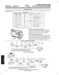
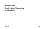
CONFIGURATION AND
TERMINAL OUTPUTS
1F72-151
1F79-111
Mounting
hole
Reset Operation 1F72-151
If a voltage spike or static discharge blanks out
the display or causes erratic thermostat operation, you can reset the thermostat by pressing
,
and TIME at the same time.
W903
Clip to
Disable
EMR
Feature
W903
O/B
Terminal
Switches
Selection
W904
Mounting Clip for
hole
Celsius
Reset Operation 1F79-111
If a voltage spike or static discharge blanks out
the display or causes erratic thermostat operation, you can reset the thermostat by pressing
,
and at the same time when system
is switched from “OFF” to “HEAT” position.
W906 for Emergency
Heat Second Stage
Fan Control
W905
Clip for
Slow Cycle
Thermostat base
Configuration Menu
1F79-111
Press Button(s)
1F72-151
Press Button(s)
Displayed
(Factory Default)
Set SYSTEM
switch to OFF
and
for at least 2 seconds
PRGM
and RUN
FA
(ON)
OFF
Select Fast (on) or slow (off) Second
Stage Heat
HOLD *
CL
(OFF)
ON
Select Compressor lockout OFF or ON
HOLD *
0 HI
(0)
3 LO TO
3 HI
Select temperature display adjustment
higher or lower
dL
(ON)
OFF
1F79-111 1F72-151
Step
Step
1
2
1
3
2
4
3
5*
4*
and
momentarily
HOLD **
6
5
Move SYSTEM
switch from OFF
RUN
and
momentarily
and
momentarily
Press
or
to select:
COMMENTS
Select display backlight OFF or ON
Return to normal operation
* Not available on earlier models
** Press HOLD to advance to next item or TIME to move backwards to previous item
THERMOSTAT
O/B
Y
Changeover
Relay*
G
W2
E
See Note **
Fan
Relay
Compressor
Contactor
Emergency
Relay
Aux
Relay
(Stage 2)
L
C
R
SYSTEM
SYSTEM
MONITOR
SWITCH
Hot
24 VAC
120 VAC
Neutral
* Changeover Relay is energized in COOL when O/B switch is in the “O” position
Changeover Relay is energized in HEAT when O/B switch is in the “B” position
TRANSFORMER
(Class II)
** Jumper required to use a single Aux Heat for both Second Stage Heat and Emergency
Typical wiring diagram for single transformer systems
NOTE
TECHNICAL HELP
If safety circuits are in only one of the systems, remove
the transformer of the system with NO safety circuits.
THERMOSTAT
O/B
CUT AND
TAPE OFF!
Changeover
Relay*
HOT
120 VAC
NEUTRAL
Y
24 VAC
Compressor
Contactor
G
W2
E
See Note **
Fan
Relay
Aux
Relay
(Stage 2)
Emergency
Relay
L
C
SYSTEM
MONITOR
SWITCH
R
SYSTEM
Limit or
Safety
Switches
Hot
24 VAC
120 VAC
Neutral
* Changeover Relay is energized in COOL when O/B switch is in the “O” position
Changeover Relay is energized in HEAT when O/B switch is in the “B” position
TWO COMMONS MUST
BE JUMPERED TOGETHER!
TRANSFORMER
(Class II)
** Jumper required to use a single Aux Heat for both Second Stage Heat and Emergency
Typical wiring diagram for two transformer systems with NO safety circuits
www.white-rodgers.com
161