1
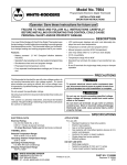
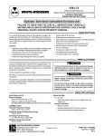
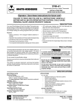
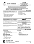
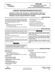
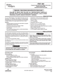
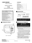
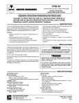
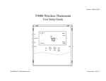
1F80-71
WHITE-RODGERS
Programmable Electronic
Digital Automatic Changeover Single Stage Thermostat
INSTALLATION AND
OPERATION INSTRUCTIONS
Operator: Save these instructions for future use!
FAILURE TO READ AND FOLLOW ALL INSTRUCTIONS CAREFULLY
BEFORE INSTALLING OR OPERATING THIS CONTROL COULD CAUSE
PERSONAL INJURY AND/OR PROPERTY DAMAGE.
DESCRIPTION
Your new White-Rodgers 5-Day/2-Day Single Stage Digital
Thermostat uses the technology of a solid-state microcomputer
to provide precise time/temperature control. This thermostat
offers you the flexibility to design heating and cooling programs
that fit your needs.
•
•
•
•
Features:
•
•
•
•
•
•
• Separate 5-day (weekday) and 2-day (weekend) programming
with four separate time/temperature periods per program
• Simultaneous heat and cool program storage
• Automatic changeover
• Optional C terminal (dual power option)
Optional Energy Management Recovery (EMR)
Optional B and O terminals
Preprogrammed temperature control
LCD continuously displays set point, and alternately displays time and room temperature
Temperature override until next program period
Manual program override (HOLD temperature)
°F/°C convertibility
Temperature range 45° to 90°F
Keypad lockout
Armchair programming capability
PRECAUTIONS
This thermostat is intended for use with a 24-volt system; do not
use this thermostat with a millivolt or line voltage system. If in
doubt about whether your wiring is millivolt, line, or low voltage,
have it inspected by a qualified heating and air conditioning
contractor or electrician.
! CAUTION
To prevent electrical shock and/or equipment damage
disconnect electric power to system at main fuse or
circuit breaker box until installation is complete.
Do not exceed the specification ratings.
All wiring must conform to local and national electrical codes and
ordinances.
This control is a precision instrument, and should be handled
carefully. Rough handling or distorting components could cause
the control to malfunction.
!
WARNING
Do not use on circuits exceeding specified voltage.
Higher voltage will damage control and could cause
shock or fire hazard.
Do not short out terminals on gas valve or primary
control to test. Short or incorrect wiring will damage
thermostat and could cause personal injury and/or
property damage.
SPECIFICATIONS
ELECTRICAL DATA
Electrical Rating:
8 to 30 VAC 50/60 Hz. or D.C.
0.05 to 1.5 Amps (Load per terminal)
1.5 Amps Maximum Total Load (All terminals combined)
THERMAL DATA
Setpoint Temperature Range:
45°F to 90°F (7°C to 32°C)
Operating Ambient Temperature Range:
32°F to 105°F
Operating Humidity Range:
0 to 90% RH (non-condensing)
Shipping Temperature Range:
-40°F to 150°F
WHITE-RODGERS DIVISION
EMERSON ELECTRIC CO.
9797 REAVIS ROAD
ST. LOUIS, MISSOURI 63123-5398
APPLICATIONS
For use with:
•
Standard heat/cool or heat only systems
•
Electric heat systems
•
Gas or oil fired systems
•
Gas systems with intermittent ignition devices (I.I.D.)
and/or vent dampers
•
Hydronic (hot water or steam) systems
DO NOT USE WITH:
•
Multi-stage systems
•
Systems exceeding 30 VAC and 1.5 amps
•
Millivolt systems
•
3-wire zoned hydronic heating systems
Printed in U.S.A.
PART NO. 37-6120A
9934
INSTALLATION
REMOVE OLD THERMOSTAT
1. Shut off electricity at the main fuse box until installation is
complete. Ensure that electrical power is disconnected.
2. Remove the front cover of the old thermostat. With wires
still attached, remove wall plate from the wall. If the old
thermostat has a wall mounting plate, remove the thermostat
and the wall mounting plate as an assembly.
3. Identify each wire attached to the old thermostat using the
labels enclosed with the new thermostat.
4. Disconnect the wires from old thermostat one at a time. DO
NOT LET WIRES FALL BACK INTO THE WALL.
5. Install new thermostat using the following procedures.
W903
CUT TO
DEFEAT EMR
GAS ELECTRIC
PRE-INSTALLATION SET-UP
1. Remove the packing material from the thermostat.
2. This thermostat is configured from the factory to operate a
heat/cool, fossil fuel (gas, oil, etc.), forced air system. It is
configured correctly for any system that DOES NOT require
the thermostat to energize the fan on a call for heat.
If your system is an electric heat or heat-pump system that
REQUIRES the thermostat to turn on the fan on a call for
heat, locate the GAS/ELECTRIC switch on the back of the
thermostat (see fig. 1) and switch it to the ELECTRIC
position. This will allow the thermostat to energize the fan
immediately on a call for heat. If you are unsure if the heating/
cooling system requires the thermostat to control the fan,
contact a qualified heating and air conditioning service
person.
3. Two jumpers are also located on the back of the thermostat,
so that you may customize the thermostat to meet your
individual preference (see fig. 1). In most applications, the
factory jumper settings provide the most comfortable and
convenient thermostat operation.
Jumper wire W905 determines how fast the system cycles
on and off, based on temperature change. As shipped from
the factory, the thermostat will maintain a very consistent
room temperature, usually within 1°F of the thermostat
setting. To achieve a slower on and off cycle, providing a
slightly wider temperature span, cut and separate jumper
wire W905.
Jumper wire W903 controls the Energy Management Recovery (EMR) feature. EMR allows the thermostat to energize
the heating system up to 30 minutes before the time programmed into the thermostat. The thermostat will then
energize the system to gradually raise the temperature to
your programmed temperature by using the most efficient
stage of heat practical.
For example, assume that the thermostat is programmed
overnight to 66°F and the room temperature is 66°. If the next
program is 7 AM, 70°F (an increase of 4°), the thermostat will
start the system 30 minutes before 7 AM. If the temperature
in the room is within 2°F of your next programmed temperature, the thermostat will not start the system early.
DO NOT clip jumper wire W903 unless you wish to permanently disable the EMR feature.
2
W905
CUT FOR
LONGER
CYCLES
Figure 1. Back of thermostat base
Alkaline batteries (3 “AA”–
install “+” ends to the left)
Screw anchors
C
W
O
R
B
G
Y
Reset
button
Mounting
holes
Figure 2. Thermostat base
INSTALLING THE THERMOSTAT
1. Gently remove the cover by pulling it straight off the base.
Forcing or prying on the unit may cause damage to the unit.
2. Remove the battery tab. With the batteries installed, the
Armchair Programming feature allows you to program the
thermostat before installing it on the wall.
3. Pull wires through the hole in the thermostat base and place
the base over the hole in the wall. Mark mounting hole
locations on the wall using the base as a template.
4. Move the base out of the way. Drill mounting holes.
5. Fasten the base loosely to the wall, as shown in fig. 2, using
two mounting screws. Place a level against the bottom of the
base, adjust until level, and then tighten the screws. (Leveling is for appearance only and will not affect thermostat
operation.) If you are using existing mounting holes, or if the
holes drilled are too large and do not allow you to tighten the
base snugly, use plastic screw anchors to secure the base.
6. Check that the system is turned off. Connect the wires
beneath the terminal screws on the base using the appropriate wiring diagram (see figs. 3 through 5).
7. Push excess wire into wall and plug hole with a fire-resistant
material (such as fiberglass insulation) to prevent drafts from
affecting thermostat operation.
(Instructions continue on page 4.)
NOTE
NOTE
The following wiring diagrams show typical terminal identification and wiring. For proper installation, refer to the original
manufacturer's instructions.
Relay contacts shown are thermostatically operated.
* The 24 Volt neutral connection
to terminal C on the thermostat
is not required if you replace
the batteries once a year with
fresh “AA” Energizer® alkaline
batteries.
Thermostat
Control
Circuit
THERMOSTAT
B
O
Y
G
W
C*
R
SYSTEM
Cooling
System
Energized
in HEAT
Heating
System
Hot
24 VAC
Neutral
Fan
Relay
Energized
in COOL
120 VAC
TRANSFORMER
Figure 3. Typical wiring diagram for single transformer systems
* The 24 Volt neutral connection
to terminal C on the thermostat
is not required if you replace
the batteries once a year with
fresh “AA” Energizer® alkaline
batteries.
Thermostat
Control
Circuit
THERMOSTAT
CUT AND
TAPE OFF!
Y
G
B
O
C*
W
R
SYSTEM
Hot
120 VAC
Cooling
System
24 VAC
Energized
in COOL
Heating
System
Hot
Neutral
24 VAC
TRANSFORMER
120 VAC
Neutral
Energized
in HEAT
Fan
Relay
TRANSFORMER
TWO COMMONS MUST
BE JUMPERED TOGETHER!
Figure 4. Typical wiring diagram for two-transformer systems with NO safety circuits
* The 24 Volt neutral connection
to terminal C on the thermostat
is not required if you replace
the batteries once a year with
fresh “AA” Energizer® alkaline
batteries.
Thermostat
Control
Circuit
THERMOSTAT
Y
G
O
B
W
C*
R
SYSTEM
Cooling
System
Heating
System
Energized
in COOL
Limit or
Safety
Switches
Fan
Relay
24 VAC
120 VAC
Limit or
Safety
Hot
Switches
Neutral
Energized
in HEAT
24 VAC
Accessory
Relay N.O.
Contact
HEATING
TRANSFORMER
Common
TWO COMMONS MUST
BE JUMPERED TOGETHER!
Limit or
Safety
Switches
Common
24 VAC
120 VAC
Limit or
Safety
Hot
Switches
Neutral
COOLING
TRANSFORMER
Figure 5. Typical wiring diagram for two-transformer systems with safety circuits in BOTH systems
3
CHECK THERMOSTAT OPERATION
LOCKOUT BYPASS OPTION
NOTE
If at any time during testing, your system does not operate
properly, contact a qualified serviceperson.
Fan Operation
1.
2.
3.
4.
Turn on power to the system.
Press SYSTEM button until the system is OFF.
Move FAN switch to ON. The blower should begin to operate.
Move FAN switch to AUTO position. The blower should stop
within a short period of time.
Heating System
FOR QUALIFIED SERVICE TECHNICIANS’ USE
ONLY. OPERATORS SHOULD NOT USE THIS FEATURE DUE TO POSSIBILITY OF EQUIPMENT OR
PROPERTY DAMAGE, OR PERSONAL INJURY.
COMPRESSOR SHORT TERM
CYCLE PROTECTION
This thermostat has a built-in short term (5-minute)
time delay. During this 5-minute period, the thermostat will lock out the compressor to allow head pressure to stabilize. If you want to override this feature
1. Press SYSTEM button until HEAT is displayed. If the heating
system has a standing pilot, be sure to light it.
while testing thermostat operation, simply press
2. Press
and
to adjust thermostat setting above room tempera-
ture. The heating system should begin to operate.
3. Press
to adjust temperature setting below room tem-
perature. The heating system should stop operating.
Cooling System
This thermostat has a built-in short-term (5-minute) time delay.
This feature is activated after the compressor shuts down and
the setpoint is changed within the 5-minute period. During this
5-minute period, COOL will flash on the display indicating that
the thermostat has locked out the compressor to allow head
pressure to stabilize. This thermostat does not sense AC power
loss and therefore does not activate the short term compressor
protection feature when power is restored.
! CAUTION
To prevent compressor and/or property damage, if the
outdoor temperature is below 50°F, DO NOT operate
the cooling system.
1. Press SYSTEM button until COOL is displayed.
2. Press
to adjust thermostat setting below room tempera-
ture. The blower should come on immediately on high speed,
followed by cold air circulation
3. Press
to adjust temperature setting above room tem-
perature. The cooling system should stop operating.
4
buttons at the same time.
DO NOT USE THE LOCKOUT BYPASS OPTION
UNLESS THE COMPRESSOR OIL HEATERS HAVE
BEEN OPERATIONAL FOR 6 HOURS AND THE
SYSTEM HAS NOT BEEN OPERATIONAL FOR AT
LEAST 5 MINUTES.
OPERATION
Before you begin programming your thermostat, you should be
familiar with its features and with the display and the location and
operation of the thermostat buttons. Your thermostat consists of
two parts: the thermostat cover and the base. To remove the
cover, gently pull it straight out from the base. To replace the
cover, line up the cover with the base and press gently until the
cover snaps onto the base.
2
1
THE THERMOSTAT BASE
SET TIME VIEW PRGM RUN PRGM HOLD TEMP
Other than
and
SYSTEM
AUTO
FAN ON
, the following buttons and switches are
COOL-OFF-HEAT-AUTO
located behind the door on the bottom of the thermostat cover
(see fig. 6). Pull the door down to open it.
The Thermostat Buttons and Switches
3
1 (Red arrow) Raises temperature setting.
4
9
2 (Blue arrow) Lowers temperature setting.
11
4 VIEW PRGM (program) button.
5 RUN PRGM (program) button.
6 HOLD TEMPerature button.
6
7
10
MO TU WE TH FR
3 SET TIME button.
5
8
11
9
SA SU
HEAT ON
P
LK
BATT HOLD AUTO COOL ON
15 14
13 12 10
10
Figure 6. Thermostat display, buttons, and switches
7 SYSTEM button (COOL, OFF, HEAT, AUTO).
8 FAN switch (ON, AUTO).
The Display
9 Indicates day of the week.
10 HEAT is displayed when the SYSTEM button has been
pressed to put the thermostat in the HEAT mode. COOL is
displayed when the SYSTEM button has been pressed to
put the thermostat in the COOL mode. COOL is displayed
(flashing) when the compressor is in lockout mode. AUTO
is displayed when the SYSTEM button has been pressed to
put the thermostat in the automatic changeover (AUTO)
mode. ON indicates that the heating or cooling system is
running.
11 Alternately displays current time and temperature.
12 The word HOLD is displayed when the thermostat is in the
HOLD mode.
13 BATT is displayed when approximately 70% of battery life
has been exhausted.
14 Displays currently programmed set temperature (this is
blank when SYSTEM button has been pressed to turn the
system OFF).
15 LK is displayed when keypad lockout has been activated.
OPERATING FEATURES
Now that you are familiar with the thermostat buttons and
display, read the following information to learn about the many
features of the thermostat.
• SIMULTANEOUS HEATING/COOLING PROGRAM
STORAGE — When programming, you can enter both your
heating and cooling programs at the same time. There is no
need to reprogram the thermostat at the beginning of each
season.
• AUTOMATIC CHANGEOVER —If you have a heating/
cooling system, you can set the thermostat to automatically
switch from heat to cool as needed to maintain setpoint
temperature. To select this mode, press SYSTEM button
until AUTO is displayed along with HEAT or COOL, identifying the program automatically selected.
In AUTO mode, pressing
and
at the same time will
change the displayed setpoint temperature to the setpoint
of the other mode (HEAT or COOL). This allows you to
change both the HEAT and COOL setpoints, if desired.
• TOTAL KEYPAD LOCKOUT — This security feature allows you to lock out the thermostat buttons to prevent
unauthorized tampering. To select this feature after programming, press SET TIME and RUN PRGM buttons at the
same time and hold until LK is displayed. To unlock the
thermostat, press SET TIME and RUN PRGM buttons at
the same time until LK is no longer displayed.
• TEMPERATURE OVERRIDE — Press
or
until the
display shows the temperature you want. The thermostat
will override current programming and keep the room
temperature at the selected temperature until the next
program period begins. Then the thermostat will automatically revert to the program.
• HOLD TEMPERATURE — The thermostat can hold any
temperature within its range for an indefinite period, without
reverting to the programmed temperature. Press the HOLD
TEMP button. HOLD will be displayed. Then choose the
desired hold temperature by pressing
or
. The ther-
mostat will hold the room temperature at the selected
setting until you press RUN PRGM button to start program
operation again.
• °F/°C CONVERTIBILITY — Press SET TIME and HOLD
TEMP buttons until the temperature display is in Celsius. To
display Fahrenheit, repeat the process.
(Instructions continue on page 6.)
5
• TEMPERATURE DISPLAY ADJUSTMENT — Your new
thermostat has been accurately set in our factory. However,
if you wish, you may adjust your new thermostat temperature display to match your old thermostat. This can be
accomplished (within a ±4°F range) as follows:
1. Press VIEW PRGM and HOLD TEMP buttons at the
same time.
2. Press
or
to adjust the displayed temperature to
your desired setting.
3. Press RUN PRGM to resume normal program operation.
PROGRAMMING YOUR THERMOSTAT
Now you are ready to program your thermostat. This section will
help you plan your thermostat’s program to meet your needs.
For maximum comfort and efficiency, keep the following guidelines in mind when planning your program.
• When heating (cooling) your building, program the temperatures to be cooler (warmer) when the building is vacant
or during periods of low activity.
• During early morning hours, the need for cooling is usually
minimal.
Look at the factory preprogrammed times and temperatures
shown below. If this program will suit your needs, simply press the
RUN PRGM button to begin running the factory preset program.
FACTORY PREPROGRAMMING
Cooling Program for
Heating Program for
ALL Days of the Week:
ALL days of the Week:
PERIOD
1st
2nd
3rd
4th
TIME
6:00 AM
8:00 AM
5:00 PM
10:00 PM
TEMP
70°F
62°F
70°F
62°F
PERIOD
1st
2nd
3rd
4th
TIME
6:00 AM
8:00 AM
5:00 PM
10:00 PM
TEMP
78°F
85°F
78°F
82°F
Use the table at the bottom of the page to plan your program time
periods, and the temperatures you want during each period. You
may also want to look at the sample program table to get an idea
of how the thermostat can be programmed.
Entering Your Program
Follow these steps to enter the heating and cooling programs
you have selected.
Set Current Time and Day
1. Press SET TIME button once. The display will show the hour
only.
P
EXAMPLE:
2. Press and hold either
or
until you reach the correct
hour (the letter P should be displayed for PM time, which
begins at noon).
3. Press SET TIME once. The display window will show the
minutes only.
EXAMPLE:
4. Press and hold either
or
until you reach the correct
minutes.
5. Press SET TIME once. The display will show the day of the
week.
6. Press
or
until you reach the current day of the week.
If you want to change the preprogrammed times and temperatures, follow these steps.
7. Press RUN PRGM once. The display will show the correct
time and room temperature alternately.
Determine the time periods and heating and cooling temperatures for your weekday and weekend programs. You must
program four periods for both the weekday and weekend program. However, you may use the same heating and cooling
temperatures for consecutive time periods. You can choose
start times, heating temperatures, and cooling temperatures
independently for both weekday and weekend programs (for
example, you may select 5:00 AM and 70° as the weekday 1st
period heating start time and temperature, and also choose
7:00 AM and 76° as the weekday 1st period cooling start time
and temperature).
Enter Heating Program
1. If you want to change the display from Fahrenheit to Celsius
(or vice-versa), press SET TIME and HOLD TEMP at the
same time.
2. Press the SYSTEM button until HEAT is displayed.
3. Press VIEW PRGM once. “MO TU WE TH FR” (indicating
weekday program) will be displayed. Also displayed are
the currently programmed start time for the 1st heating
period and the currently programmed temperature
(flashing).
SAMPLE
Heating/Cooling Schedule Plan
WEEKEND (2 DAY)
WEEKDAY (5 DAY)
Heating/Cooling Schedule Plan
WEEKEND (2 DAY)
WEEKDAY (5 DAY)
Period
Start
Time
Temperature
Start
Time
Temperature
1ST HEAT
1ST HEAT
5:30 AM
68°F
7:00 AM
68°F
2ND HEAT
2ND HEAT
8:00 AM
65°F
11:00 AM
70°F
3RD HEAT
3RD HEAT
5:00 PM
70°F
6:00 PM
70°F
4TH HEAT
4TH HEAT
10:30 PM
65°F
11:30 PM
65°F
1ST COOL
1ST COOL
6:30 AM
76°F
7:00 AM
76°F
2ND COOL
2ND COOL
2:00 PM
78°F
12:30 PM
74°F
3RD COOL
3RD COOL
5:00 PM
72°F
6:00 PM
72°F
4TH COOL
4TH COOL
10:30 PM
78°F
11:30 PM
78°F
Period
6
Start
Time
Temperature
Start
Time
Temperature
MO TU WE TH FR
CHECK YOUR PROGRAMMING
EXAMPLE:
Follow these steps to check your thermostat programming one
final time before beginning thermostat operation.
This display window shows that for the 1st weekday period,
the start time is 6:00 AM, and 70° is the programmed
temperature (this example reflects factory preprogramming).
1. Press SYSTEM button until HEAT is displayed.
2. Press VIEW PRGM to view the 1st weekday heating period
time and temperature. Each time you press VIEW PRGM,
the next heating period time and temperature will be displayed in sequence for weekday, then weekend program
periods (you may change any time or temperature during this
procedure).
3. Press RUN PRGM.
4. Press SYSTEM button until COOL is displayed.
5. Repeat step 2 to check cooling temperatures.
6. Press RUN PRGM to begin program operation.
7. Press SYSTEM button to select HEAT, COOL, or AUTO
mode.
4. Press
or
to change the displayed temperature to your
selected temperature for the 1st heating program period.
5. Press SET TIME once (the programmed time will flash).
Press
or
until your selected time is displayed. The time
will change in 15 minute increments. When your selected
time is displayed, press SET TIME again to return to the
change temperature mode.
6. Press VIEW PRGM once. The currently programmed start
time and setpoint temperature for the 2nd heating program
period will be displayed.
7. Repeat steps 4 and 5 to select the start time and heating
temperature for the 2nd heating program period.
8. Repeat steps 4 through 6 for the 3rd and 4th heating program
periods. Weekday heating programs are now complete.
9. Press VIEW PRGM once. “SA SU” (indicating weekend
program) will be displayed, along with the start time for the
1st heating period and the currently programmed temperature.
10. Repeat steps 4 through 8 to complete weekend heating
programming.
11. When you have completed entering your heating program,
press RUN PRGM.
Enter Cooling Program
! CAUTION
If the outside temperature is below 50°F, disconnect
power to the cooling system before programming.
Energizing the air conditioner compressor during
cold weather may cause personal injury or property
damage.
YOUR THERMOSTAT IS NOW COMPLETELY PROGRAMMED AND READY TO AUTOMATICALLY PROVIDE
MAXIMUM COMFORT AND EFFICIENCY!
TROUBLESHOOTING
If your thermostat’s display is frozen or displaying incorrectly,
the thermostat may have been affected by static discharge or
voltage variations. If this happens, press the RESET button (see
fig. 2, page 2 for the location of the button). Pressing the RESET
button will clear all user programming. The thermostat will revert
to factory preprogramming. You will need to reset the time and,
if desired, reprogram the thermostat to your selected program.
If pressing the RESET button does not correct the problem,
contact a qualified service technician.
For optimum performance, we recommend replacing batteries
once a year with fresh “AA” Energizer® alkaline batteries.
1. Press SYSTEM button until COOL is displayed.
2. Follow the procedure for entering your heating program,
using your selected cooling times and temperatures.
7