1
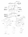
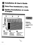
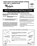
CONVERTIBLE
KITCHEN
FOR 120 V. OPERATION
RANGE HOOD
KITCHEN
RANGE HOOD
MODEL
FOR VENTLESS
USE DUCTLESS
READ AND SAVE THESE
read
the following
Before
you
begin,
completely
and carefully.
If followed,
they
the installation
job.
IMPORTANT:
SAVE
INSTALLATION
KIT RCH 9600
RH9330XL
INSTRUCTIONS
instructions
will simplify
OBSERVE
ALL GOVERNING
AND ORDINANCES
CODES
THESE INSTRUCTIONS
FOR THE LOCAL
ELECTRICAL
INSPECTOR’S
USE
WAYS TO INSTALL
VENTILATING
DUCT:
There are three ways to install the ventilating
duct.
Select the most practical
method for your particular
installation.
Figure 7: 7” dia. round venting
through
the roof.
Figure 8: Transition,
from the 7” dia. stack provided
on the hood to a 3 l/4 x 10 rectangular
duct, for roof
venting.
Figure 9: 7” dia. elbow, for horizontal
venting,
with
a wall cap.
The duct, wall cap and roof cap shown in Figure 7,8
and 9 are not included
with your range hood
These Items can be purchased
separately.
TOOLS
A---
l
-;*/
F :r
AND
\FAN
BOX
MOUNTING
SCREWS
(6)
FIGURE
MATERIALS
1
REQUIRED
Drill, electric
or ratchet drive, with 3/8”, 3/16” and l/8”
wood brt (for drlllrng starter holes) and l-1/4” wood bit
(to drill an access hole in the cabinet or kitchen wall for
the electrrc
power line.)
C”
l
l
Pliers
l
Pencil,
l
l
A626-127
830878
One common
and one ohllllps
head screwdriver
(to
secure hood mounting
screws to the cabinet and hood
sheet metal parts).
(for opening
ruler
knockouts).
and level
for marking
Saber saw or keyholesaw
openings.
Caulkrng,
transitron,
required.
for cutting
cabinet
locattons.
the wall or cabinet
metal snips, duct tape, ducts (with elbow and
If necessary)
and wall cap or roof cap, as
Page
1
3-17-82
INSTALLATION
IJNDEQ
KITCHEN
F’JFQ
‘I)O’i’!Y
hood on mounting
screws
and mark
4. Hang
location for venting and wiring. Remove canopy
to cut holes.
hood should be
1. For easy, one man I-staliation
disassembled.
First, remove the aluminum
filter from fan box
assembly
by pulling tab toward opposite
end of
filter.
Remove two mount ng screws fcund in fan box
near back. (Figure
:.)
Unplug
power
supply
cord connection
near
back.
Remove
additional
four screws
from fan box
assembly
and lift assembly
out.
iisrnode
tour scret.cs nolcrng
top to canopy
assem biy
FOR
TOP
VENTING:
Mark
venting
locations
through
the
ceiling
or
obstructions
between
hood top and attic.
7’6” diameter
hole for round venting
(Fig.
a 3;;” x 10’,q” h~,e for rectanglr,a-,,~nili:g,
hole
other
Cut a
7) or
Fig. 8.
FOR WALL VENTING:
Establish
the center for
the back vent hole bv measurina
half the width
of the hood and down 1 O-1/4” from canopy top.
See Figures 2 and 9.
FOR DUCTLESS
INSTALLATION:
Refer to
instructions
found in ductless
kit RCH 9600 for
remaining
installation
procedure.
2, 7 8 8)
2. Fa3R TOP VENTING:(Figures
Using the canopy ?oo as a hole !ocating pattern,
make a 7’/4” diameter
hole.
If the optional
rectangular
transition
is to be used, make a
3’b”xlO’;;”
rectz:.juirar
hole. Mark an- c*: ,.;;e
for wrring.Flanged
hole is provided
in canopy
for wiring entrance
5. Replace
hood
and tighten
6. Make electrical
back of canopy
screws
connection
according
at wiring at box on
to Figures 3 & 6.
7. Witn nec?ssar:/
duct tn place (see Figure 4; ‘*rt
fan box assembly
into posrtion and secure >,*ylth
six screws.
8. Plug hood power supply
into receptacle.
FOR WALL VENTING:
(Figures 2 & 9) Establish
center
line for the hole pattern
by measur’ng
half the width of the canopy and 10%” from the
top of the canopy.
Make a 7%” diameter
hole
through
the wall. Mark and cut hole for wlrlng
F!anged
hole is provided
in canopy
top for
wiring entrant
9. Replace
FUAR
FCP DUCTLfSS
, INSTALLATION:
Refer
to
InstructIons
found in ductless
kit RCH 9600 for
remarnrng
installation
procedure.
filter.
-~ HOLE
PATTERN
FOR
TOP VENTING
ONLY
DOWN ~F
CANOPY
TOP ~-\
3. Install canopy top to kitchen furr down with four
screws provided
in installation
pack, Fig. 5.
4. Install canopy
assembly
by sliding top flanges
of canopy
assembly
onto mating
flanges
on
canopy
top, Figure
5. Secure
with 4 screws
prevrously
removed.
5. Make electrical
back of canopy
3&6
connection
at wiring
box on
assembly
according
to Figures
duct work in place
6. With necessary
lift fan box assembly
into position
with 6 screws.
7. Plug
hood
8. Replace
power
DOORS
supply
~
7;‘TO
7;‘lNCH
CENTER
LINE
OF HOOD
DIA
HOLE
FOR BACK
VENTING
ONLY
(see Fig. 4),
and secure
7” ROUND
into receptacle.
FIGURE
2
DUCT
filter.
KEYHOLE
MOUNTING
HOLE
FREE STANDING
WALL INSTALLATION:
1. For easy, one man Installation,
hood should be
:+sassnm5ls<
First, remove the aluminum
tilter from tne fan
box assembly
by pulling
tab toward opposite
end of filter.
Remove
two mounting
screws
found in fan box near back. (Figure
1)
Unplug
power supply cord connection
near
back Remove additional
four screws from fan
box assembly
and lift assembly
out.
?
I
*I
y,pTr“,,
“C’T-!hli,
,ap.-J
mark
lorytion
for 2
i. no,55 dt r ii;’ c: <(t-y I1oie -,3is. i,i!;Jre
:r;OainiI:-.g
HOOD
WIRING
--4
LIZ
1
FIGURE
ELECTRICAL
‘-1”
WIDE
FLANGE
ON
HOOD BACK
3
GROUNDING:
Permanently
ground
this unit in accordance
with
the latest National
Electrical
Code and applicable
local codes and ordrnances.
It is recommended
that
a permanent
ground connection
be made to the untt
using
a conductor
of appropriate
size from a
grounded
continuous
metalltc
cold water pipe, a
grounded
lead in the service
panel or a properly
driven and electrically
grounded
ground rod. Do not
ground
to a gas supply pipe.
4)
3. Insert screws Into n-arkea location
leaving l/l6
to l/8 inch between
wall and screw head.
NOTE:lf
hollow sheetrock
wall IS encountered,
molly
bolts should
be used instead
of those
provided
In installation
packet.
AddItional
support
should
be provided
after canopy
is in
place, when hollow wall molly bolts are used.
Page
2
/-CANOPY
TOP
KEY HOLESLOTS
CANOPY MTG.m
SCREWS (4)
I
1
-
I
FAN BOX MTG.-~\*,<pJ
SCRE”‘”
‘*’
I
’
FAN uvm I.. I -.
SCR EWS (2)
I
I
I
I
b’
POWER
CORD
SUPPLY
n
CANOPY TOP ATTACHED
TO FURR DOWN
-__
I----’
24”
APPRCX
1 CCCl(
1
I
SbRFACE
FIGURE
” FIGURE
7
Page 3
8
FIGURE
9
IMPORTANT
SAFEGUARDS
FOR ELECTRICAL
When
using
electrical
appliances.
basic
safety
precautions
should
always
be followed
including
the following:
1. Read and follow all instruc?ions.
2. Cl052
supervisso?
is r. .- --~-?-TV vdh2.n
appliance
is used by or near children.
APPLIANCES
4. Do
not
saturate
switches,
and motor
Remember,
WATER
NOT MIX!
electrical
connections,
in water during cleaning.
AND ELECTRICITY
DO
5. If any e!ectrical
malfunction
becomes
during
3~. alsconnect
power to nood
home fuse or breaker
box.
any
evident
at yoc;r
3 To avoid providing
fuel for a grease
pan fire
clean lint and grease from all hood surfaces
interior
and exterior.
OPERATION
CAUTION:
Do not use lamp larger than 75 watts.
Unit is designed
to accept 75 watt flood
greater
i’lllr?ination
and bulb life.
AND CARE OF UNIT
CARE OF EXTERIOR
lamp
for
SURFACES:
Your range hood is a beautifully
finished addition
to
your kit&“rl
and requires
only the care you give
your range io preserve
its lasting beauty. Clean wth
a mild detergent
to preserve
finish.DO
NOT use
abrasive
c/ea:~zs.
CARE OF FILTER:
For
greatest
eff;cier;cy.
the
perrnapect-type
aluminum
foil grease
filter should
be removed
&
cleaned
periodically.
To clean, the filter snould be
soaked in hot water and detergent.
TO remove filter, pull tab to side and pull filter down
and out. To replace
reverse the procedure.
For effective
removal of smoke and odors, turn on fz- 2’
beginning
of cooking
operation
and allow to run until
smoke and odors are removed
from room.
CARE OF FAN MOTOR:
Fan motor has life time seaied bearings
that never
rIe?d ?Illng. Occasil;
‘.:~. ;leanlng
01 moic:
may be
required.
Do not emcrse in water.
CLEAN
ALL
FREQUENTLY.
GREASE
If you need ser-2:
1.
Before
If nothing
l
Have
problems
without
SURFACES
L or assistance,
we suggest
for assistance...
calling
Performance
ant fox yourself
LADEN
often
tools
result
from
htlle
3
things
you follow
If you
l
need
these four
service...
you can find
WhIrlpool
wide
network
TECH-CARE
Companies.
operates;
you
checked
the maln
fuse
or clrcult
breaker
steps:
box?
service
trained
warranty
has a natlonof franchised
R Service
TECH-CARE
technicians
are
to fulftll the product
and provide
sfter-
warranty
service
anywhere
In the Untted States.
To locate TECHservice
In your area, call our COOL-LINE
service
assistance
telephone
number
(see Step 2) or look In your telephone
dtrec!ory
Yellow
Pages under:
CARE
2.
If you
need
assistance...
Call the Whirlpool
COOL
number.
Dial free from:
Conlinenlal
U.S.
Michigan
AlaskaKHawall..
-LINE’
service
assistance
APPLIANCES-HOSEHOLD
MAJOR-SERVICE
telephone
WHIRLPOOL
FRANCHISED
(BOO) 253-1301
(800) 632-2243
(800)253-1121
ELECTRICALAPPLIANCESMAJOR--REPAIRING
8 REPAlR
APPLIANCES
TECH-CARE
SERVICE
COMPANiES
XYZ SERVICE
CO
123 MapIf,
OR
SERVICE
WHIRLPOOL
FRANCHISED
999-9999
SERVICE
COMPANIES
XYZ SERVICE
CO
123 hlaple
OR
WASHING
MACHINES,
8 IRONERS-SERVICING
and talk with one of our tralnod
Consultants
The Consultant
can
Instruct
you In how to obtain
satisfactory
operatton
from your
appliance
or If service
IS necessary,
recommend
a qualtfled
service
company
in your area
WHIRLPOOL
FRANCHISED
APPLlANCES
TECH-CARE
SERVICE
COMPANIES
XYZ SERVICE
CO
123 Maple
4.
If you
have
APPLIANCES
TECH-CARE
8 PARTS
SERVICE
999.9999
DRYERS
SERVICE
999-9999
a problem...
C,jli our COOL-LINE
service
assistance
Step 2) and lalk with oneof our Consultants.
telepone
number
(see
or If you prefer, write to
Mr Guy Turner.
Vice President
WhIrlpool
Corporation
AdmInIstratIve
Center
2000 US-33 North
Benton
Harbor,
MI 49022
Page
4
If you must call or write.
please
provide
model
number,
serial
number,
date of purchase,
and a complete
descrrptlon
of the
problem
This Information
IS needed
In order to better respond
to
your request
for assistance