1
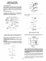
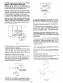
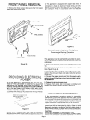
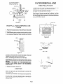
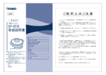
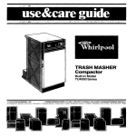
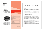
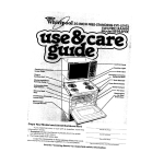
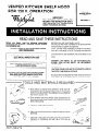
VENTED KITCHEN SHELF
FOR 120 V. OPERATION
HOOD
I
IMPORTANT
FOR VENTLESS INSTALLATION,
DISREGARD THIS INSTRUCTION
SHEET.
USE VENTLESS
KIT INSTRUCTION
SHEET FOR MODEL RCH3660.
KITCHEN
RANGE HOOD
MODEL
RH3330XL-1
READ AND SAVE THESE INSTRUCTIONS
Before you begin, read the following
instructions
completely and carefully. It followed, they will simplify
the installation job.
‘PJJORTANT: OBSERVE ALL GOVERNING CODES
AND ORDINANCES
BEFORE YOU USE YOUR SHELF HOOD:
Be sure your shelf hood is installed on an appropriate
wall
strong enough to support this appliance.
NOTE: The shelf hood is designed to support a microwave
oven with a net weight of up to 75 pounds, plus approved
accessories, cookbooks, utensils, and food.
The area used for the installation
must be suitable for the
size, function, and protection
(from elements) of the shelf
hood.
SAVE THESE INSTRUCTIONS
FOR THE LOCAL
ELECTRICAL
INSPECTOR’S USE
WARNING:
THE
EXCEED
YOUR
ASSISTANCE.
FOR USE WITH WHIRLPOOL “J” AND “L”
LINE MICROWAVE OVENS
WEIGHT
LIFTING
OF THE
ABILITY.
MICROWAVE
MAY
WE RECOMMEND
CAUTION:
When mounting the shelf hood to a wall, you
must locate 2 studs in the wall. Do not attempt to install the
hood if the 2 wall studs are not found.
FOR USE OVER WHIRLPOOL CONVENTIONAL
GAS AND ELECTRIC RANGE COOKTOPS
-
Be careful when drilling holes into awall. Electrical wires and
water pipes may be concealed behind the wall covering.
TOOLS AND MATERIALS
l
Drill, electric or ratchet drive, with 3/8”, 3/16” and l/8”
wood bit (for drilling starter holes) and l-1/4” wood bit
(to drill an access hole in the cabinet
the electric
power line.)
l
One common
l
Pliers
l
Pencil,
l
l
-512/&j
3/ 79
REQUIRED
or kitchen
wall for
and one phillips
head screwdriver
(to
secure hood mounting
screws to the cabinet and hood
sheet metal parts).
(for opening
ruler
knockouts).
and level for marking
cabinet
locations.
Saber saw or keyhoie saw for cutting the wall or cabinet
openings.
Caulking,
transition,
required.
metal snips, duct tape, ducts (with elbow and
if necessary) and wall cap or roof cap, as
Page 1
INSTALLATION
REQUIREMENTS
TRANSITION-
A. Space Requirements
A typical installation can be seen in Figure 1. Study Figure 1
before proceeding. The shelf hood requires an opening that
is 30” wide. It is recommended
that the cabinet above the
cooktop be a maximum
of 15” high. This provides the
adequate space btween the range cooktop and the shelf
hood.
B. Electrical Requirements
A 120 Volt, 60 Hz, AC only, 20Ampere fused electrical supply
is required
(Time delay
fuse or circuit
breaker
is
recommended).
It is recommended
that a separate circuit
serving only this appliance be provided.
3% X 10 THRU WALL
(8.3 X 25.4 cm)
Figure
3
IMPORTANT: WALL AND ROOF CAPS MUST HAVE BACKDRAFT DAMPER.
NOTE: Ductwork, wall and roof caps not supplied with hood.
3%” X 10 to ROUND (7” MIN. DIAMETER)
THRU ROOF
Figure
4
INSTALLATION
VENTING
1. Select the area for installation,
making sure you have an
electrical supply available. See the shaded area (Figure 5).
This is the area the electrical supply must enter.
REQUIREMENTS
ELECTRICAL
ROUGH-IN AREA
Before you begin, determine where the ductwork will run.
For best performance,
keep the length of ductwork and the
number of elbows to a minimum.
Illustrated are some of the more common methods. (Figures
2,3. and 4).
IMPORTANT:
THE VENTING SYSTEM MUST TERMINATE
TO THE OUTSIDE. DO NOT TERMINATE THE VENT IN AN
ATTIC OR OTHER ENCLOSED SPACE. THIS MAY RESULT
IN A FIRE HAZARD.
ROOFCAP
-USE
LEVEL-
Figure
Figure
\
5
CAUTION: Due to the amount of weight the shelf hood mUSt
support, make sure the hood is mounted to two vertical 2x4
wall studs with the four lag bolts and into the wall covering
(I/Z” sheet rock minimum) with the four anchor bolts. Lag
bolts and anchor bolts (eight in all) are supplied in the Inslallation Assembly.
2. If the shelf hood is mounted to a wall that does NOT meet
the above recommendations,
the weight of the microwave
oven may cause the hood to pull away from the wall resulting
in personal injury or property damage.
3. Mark a line on the back wall 15” down from the upper
cabinets centered between the side cabinets or the allotted
space. Use a level. (Figure 5).
2
Page 2
CAUTION:
If two studs are not located on the line drawn
(Figure 5). DO NOT attempt to install the hood.
NOTE: If the shelf hood is to be installed
above a
Freestanding
Range, disconnect the power from the range
and move the range out of the opening in the cabinets. This
will allow for more access to the installation area.
If installing the shelf hood above aBuilt-in Cooktop orSet-in
Range, lay a protective cover over the cooktop during the
installation.
This may help prevent damage to the cooktop
(in case you drop something) and it will prevent dust and dirt
from accumulating
on the cooktop during installation.
4. Line the top of the hanging bracket up with the line drawn
on the wall in Figure 5. Move the bracket to the left or right
within the allotted 30” space until the center line of the 2
studs line up with 4 holes in the hanging bracket. Neither
edge of the bracket should be closer than %” to the side
cabinets or the end of the 30” allotted space. (See Figure 6).
5. Mark and drill four 3/16 dia. holes in the studs for the l/4”
dia. X 2” lage bolts provided.
I
II
:,:
Figure 6
11. The hole in the bottom of the cabinet (for the duct
provided with the hood) should be cut as shown in Figure 6
(15%” long by 1%” deep). Hole must be cut to back wall.
Make sure to center the hole within the 30” alloted space.
12 Rough wire the electrical supply to the area shown in
Figure 5.
13 Hang the shelf hood on the hanging bracket. To be sure
the shelf hood hanging angle is completely engaged in the
hanging bracket, measure from the top of the shelf hood to
the top of the hangrng bracket. This distance shoud be
l-7/16 on both sides.
CAUTION: Do not continue until both ends measure l-7/16”.
If the hanging angle is not fully engaged in the hanging
bracket, the shelf hood will not be level and the hood may
become dislodged
from the hanging bracket. This could
cause damage.
II
CLEARANCE
TO CABINET
14. If your micro shelf hood is located between cabinets, you
can fasten theside panels to the cabinets. To do this, remove
the two #0x%” slotted
round head screws
from the
installation
assembly. Locate the 3/16” diameter holes on
either side of the hood (eleven inches from the rear and one
inch from the bottom). Securely fasten both sides of the
hood to the cabinets.
Figure 6
15. Complete the duct work by:
A. Fit the duct provided with the shelf hood on to the vent
outlet of the shelf hood.
6. Mark 2 holes on each end of the hanging bracket. Remove
bracket and drill four %‘I dia. holes.
7. Insert four hollow wall anchor bolts into the four 3/s” dia.
holes in the sheet rock. Anchor bolts are provided
in
installation
pack.
Rotate
anchor
bolts screws
5-10
revolutions to hold each anchor bolt in place. These will be
completely
tightened later. (See Figure 7).
6. Remove all 4 screws from the anchor bolts.
9. Attach hanging bracket to the wall with the four screws
taken from the anchor bolts. Tighten the screws in the
anchor bolts until the anchor bolts are completely set.
10. Install four remaining
Vi” dia. lag bolts through the
hanging bracket and into the two studs.
HOLLOW
ANCHOR
B. Mark and drill (2) ‘/a” dial holes (1 each side) to fasten the
thin duct provided with the hood to the back wall. See
Figure 9.
C. Use 2 #6 xl/g long screws provided
the narrow thin duct to the shelf.
with the unit to fasten
D. Next install the transition adaptor to the thin duct. This
transition adaptor will accept 3%” X 10” duct.
E. Completethe
%“XlO”duct(orequilvalent)
using the guidelines listed under venhng
WALL
BOLT
Figure 7
CAUTION:
Do not overtighten
the lag screws. If they are
overtightened,
the bracket may pull into the wall material
which will not allow the shelf to slide into place properly.
\Fig&e
Page 3
,
totheoutside
requirements.
FRONT PANEL REMOVAL
1. Remove the three screws that secure
lower and remove front panel.
the front
panel;
2. This appliance
is equipped with copper lead wires. If
connection
is made to aluminum house wiring, use only
special connectors which are approved for joining copper
and aluminum
wires in accordance
with the National
Electrical Code and local codes and ordinances.
FRONT PANEL
SWITCH KNOBS
\
\
b
PANEL SCREWS
.. 8
Figure
\
12
Electrical Ground is Required on This Appliance
Recommended
Electrical Connection
and Grounding Method
Q+
FRONT
;ANEL
HOOD FLANGE
This appliance
must be permanently
grounded
in accordance with the National Electrical Code and local codes and
ordinances.
Figure
10
1. Remove
12).
the terminal
access cover. (See Figures
2. Install a strain relief into the opening
box. (Figure 13, pg. 5).
11 and
of the wire junction
3. Connect the white and black wires of the power supply
cable to the white and black wire leads inside the terminal
access box.
PROVIDING ELECTRICAL
POWER
IT IS THE PERSONAL
RESPONSIBILITY
AND OBLIGATION OF THE CUSTOMER
TO CONTACT
A QUALIFIED
INSTALLER
TO ASSURE THAT THE ELECTRICAL
INSTALLATION
IS ADEQUATE AND IS IN CONFORMANCE
WITH THE NATIONAL
ELECTRICAL
CODE AND LOCAL
CODES AND ORDINANCES.
1. Connect the wiring to the junction box through flexible
armoured
or nonmetallic
sheathed
copper cable (with
REMOVE
7/8”DlA
KNOCK
WIRING TO JUNCTION
80X
OUT
--
FOR
.~
tot-
4. Connect the green ground wire from the power supply
cable to the end of the green ground wire provided in terminal access box.
5. Replace
the terminal
access cover.
6. Replace front panel after microwave
is installed
leveled using leveling bolts as shown in Figure 14.
-ALTERNATE
and
GROUNDING-
If the recommended
grounding
method is impossible,
permanently
ground the appliance from the green ground
//<Z
wire (located it-i the terminal access box) to a grounded cold
water pipe’ using a separate, green colored, insulated
copper conductor of appropriate
size (no.16 minimum).
*Cold water pipe must have metal continuity
to electrical
ground and not be interrupted
by plastic, rubber or other
electrically
insulating connectors (including water meter or
pump) without adding a jumper wire to these connections.
Figure 11
CAUTION:
ground wire). A suitable strain relief must be provided at
(a) DO NOT GROUND TO GAS SUPPLY PIPE.
each end of the power supply cable (at appliance and at the
(b) DO NOT CONNECT TO ELECTRICAL
SUPPLY UNTIL
junction box.
APPLIANCE
IS PERMANENTLY
GROUNDED.
Page 4
RECEPTACLE
Y&c.
,WIRING
DONE ACCORDING
NATIONAL
ELECTRICAL
AND APPLICABLE
LOCAL
FILTER REMOVAL
INSTALLATION
TO
CODE
CODES1
RECEPTACLE
AND
The aluminum filter is held in place with the two filter clips
located on the front panel. (See illustrations
below).
To remove the filter, simply turn the filter clips to the front of
the hood. The filter can now be removed.
To replace the filter, place one end of the filter beneath the
back flange of the panel and set filter in position. The filter
will set over the blower housing with the other end flush on
the lower flange of the front panel. Turn the filter clips to the
rear until the filter is secure.
TERMINAL
ACCESS
COYER
Figure 13
FILTER
CLIPS
INSTALLING
MICROWAVE
OVEN
1. Place the microwave oven on the
of the hood.
2. Use the leveling bolts provided to
the weight of the appliance is placed
in the installation
Assembly. Screw
shelf hood in the center
level the shelf hood after
on it. Bolts are provided
the bolts into the nuts
FILTER
INSTALLED
Figure 15
FILTER CLIP /
-~ -\
Figure 16
Figure 14
provided on the lower left and right hand sides of the hood
until the unit is level. (Figure 14) Use a level.
NOTE: The leveling bolts have a 9116” Hex Head.
CAUTION: The mlcrowave oven must be level from front to
back to minimize utensils from sliding forward when openlng
the door.
WARNING:
THE WEIGHT OF THE MICROWAVE
MAY
EXCEED YOUR LIFTING
ABILITY.
WE RECOMMEND
ASSISTANCE.
3. Replace
BLOWER
HOUSING
F’LTER
FILTER INSTALLATION
front panel. (Figure 10)
Figure 17
LIGHTING
Select two light bulbs up to 60 watts each to achieve the
desired lighting.
The bulbs may be installed or removed by removing the filter.
Once the filter is removed, adequate space is provided on
either side of the filter area for installation or removal of the
bulbs by hand.
Page 5
FRONT
SIDE PANEL INSTALLATION
The side panels can be used to fill the space left on a 30”shelf
hood when the microwave oven is centered on the hood.
Locate the magnetic
tape on the side panels prior to
installation.
(Figure 20).
The front of the side fillers should be located 5/16” back from
the front of the Micro Shelf hood. This will allow sufficient
space for the door opening.
/
MAGNETIC
TAPE
NOTE: Optional
Cookbook
Storage
Cabinet,
RCK902
(832873) may be placed on the left side of the microwave in
lieu of the side panels.
-MAGNETIC
TAPE
1.
B e f ore calling
20
or assistance,
LIGHTS
Do not use bulb larger than 60 watts in light socket.
CARE OF EXTERIOR SURFACES
Your range hood is a beautifully
finished addition to your
kitchen and requires only the care you give your range to
preserve its lasting beauty. Clean with a mild detergent to
preserve finish. DO NOT use abrasive cleaners.
For most effective removal of smokeand odors, turn on fan at
beginning of cooking operation and allow to run untilsmoke
and odors are removed from the room.
we suggest
3.
for assistance...
you follow
these four steps:
If you need service...
Performance problems often result from little tnmgs you can find
and fix yourself without tools.
Whirlpool has a nationwide network of franchised
TECH-CARE@
Service
TECH-CARE
Companies.
II nothing operates;
.
Have you checked
the main fuse ‘omit
breaker
MA6Fc
AND CARE OF UNIT
CARE OF FILTERS
A. ALUMINUM
FILTER:
For greatest
efficiency,
the
permanent
type aluminum
filter should be removed and
cleaned periodically.
To clean, the filter should be soaked in
hot water and detergent,
then thoroughly
rinsed. The
aluminum filter can be cleaned in a dishwasher.
CARE OF FAN MOTOR
Fan motor has life time sealed bearings that never need
oiling under normal usage. A few drops on each bearing after
three years of heavy usage will prolong the motor life. Clean
motor with a damp cloth and grease cutting detergent when
a heavy coating of grease has accumulated.
If you need service
/
ONE SIDE PANEL ON EACH
SIDE OF MICROWAVE OVEN
Figure
OPERATION
ml
box?
service
technicians
are
trained to fulfill the product
warranty and provide afterwarranty service anywhere In the United States. To locate TECHCARE service
2.
If you need assistance...
Call the Whirlpool
COOL
number. Dial free from:
Continental U.S.
Michigan
Alaska & Hawaii.
in your area, call our COOL-LINE
service
assistance
telephone number (see Step 2) or look in your telephone directory
Yellow Pages under:
-LINE@ service
assistance
APPLIANCES-HOSEHOLO
MAJOR-SERVICE6
telephone
WHIRLPOOL
FRANCHISED
.
.
(600) 253-1301
(600) 632-2243
(600) 253-1121
ELECTRICALAPPLIANCESMAJOR-REPAIRING
L PARTS
REPAIR
APPLIANCES
TECH-CARE
SERVICE COMPANIES
XYZ SERVICE CO
123 Maple
OR
SERVICE
WHIRLPOOL
FRANCHISED
999-9999
SERVICE COMPANIES
XYZ SERVICE CO
123 Maple
OR
APPLIANCES
TECH-CARE
SERVICE
999-9999
WASHING
MACHINES.
DRYERS
6 IRONERS-SERVICING
and talk with one of our tramed Consultants.
The Consultant
can
Instruct you In how to obtain satisfactory
operation
from your
appliance or, II service is necessary, recommend a qualified service
company In your area.
WHIRLPOOL
FRANCHISED
APPLIANCES
TECH-CARE
SERVICE
SERVICE COMPANIES
XYZ SERVICE CO
123 Maple
4
l
If
999-9999
you have a problem...
Call our COOL-LINE
service
assistance
telepone
number
(see
Step 2) and talk wtth one of our Consultants. or if you prefer, write lo:
Mr. Guy Turner, Vice President
Page 6
WhIrlpool Corporation
Administrative
Center
2000 US-33 North
Benton Harbor, Ml 49022
If you must call or write. please provide model number, serial
number, date of purchase,
and a complete
description
of the
problem. This mformahon
is needed in order to better respond to
your request for assistance.