1
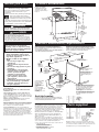
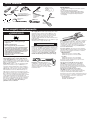
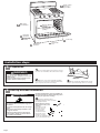
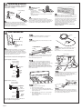
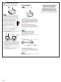
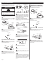
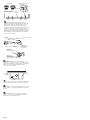
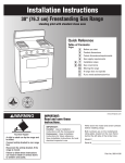
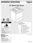
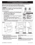
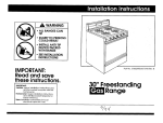
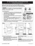
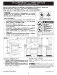
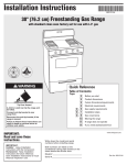
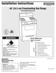
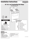
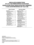
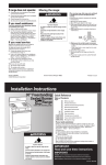
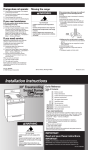
Installation Instructions
30" Freestanding
Gas Range
with standard clean oven
Quick Reference
Table of Contents:
Pages
2
Before you start
2
Product dimensions
2
Cabinet dimensions/requirements
3
Gas supply requirements
4 - 6
Installation steps
7 - 8
Gas conversions
Back cover
If range does not operate
Back cover
If you need assistance/service
Back cover
Moving the range
If you need assistance:
WARNING
Tip Over Hazard
A child or adult can tip the range and be
killed.
Connect anti-tip bracket to rear range foot.
Reconnect the anti-tip bracket, if the range
is moved.
Failure to follow these instructions can
result in death or serious burns to children
and adults.
Check your Use and Care Guide for a toll-free number to call or call the
dealer from whom you purchased this range. The dealer is listed in
the Yellow Pages of your phone directory under “Appliances —
Household — Major — Service and Repair.”
Call when you:
Have questions about range installation or operation.
Need to obtain the name and number of an authorized
service company.
When you call, you will need:
The range model number.
The range serial number.
Both numbers are listed on the model/serial rating plate located on the
frame behind the broiler door.
IMPORTANT:
Read and save these instructions.
IMPORTANT:
Installer: Leave Installation Instructions with the homeowner.
Homeowner: Keep Installation Instructions for future reference.
Save Installation Instructions for local electrical inspector's use.
Part No. 98007134 Rev. A
Before you start...
Your safety and the safety of
others are very important.
We have provided many important safety
message in this manual and on your
appliance.
Always read and obey all safety messages.
This is the safety alert symbol.
This symbol alerts you to potential
hazards that can kill or hurt you and
others.
All safety messages will be preceded by the
safety alert symbol and the word “DANGER”
or “WARNING”. These words mean:
Product dimensions
Proper gas supply
connection must be
available. See “Gas
supply requirements,”
Page 3.
26-3/4" depth
with handle
36"
cooktop
height
DANGER
46-1/4"
overall height for
tall backguard
models
You can be killed or seriously injured if
you don’t immediately follow instructions.
42-1/4"
overall height for
short backguard
models
WARNING
You can be killed or seriously injured if
you don’t follow instructions.
All safety messages will tell you what the
potential hazard is, tell you how to reduce
the chance of injury, and tell you what can
happen if the instructions are not followed.
WARNING: If the information in
this manual is not followed
exactly, a fire or explosion may
result causing property damage,
personal injury or death.
— Do not store or use gasoline or
other flammable vapors and
liquids in the vicinity of this or
any other appliance.
— WHAT TO DO IF YOU SMELL
GAS
• Do not try to light any
appliance.
• Do not touch any electrical
switch.
• Do not use any phone in your
building.
• Immediately call your gas
supplier from a neighbor’s
phone. Follow the gas
supplier’s instructions.
• If you cannot reach your
gas supplier, call the fire
department.
— Installation and service must
be performed by a qualified
installer, service agency or
the gas supplier.
Important: Observe all governing codes
and ordinances.
Do not obstruct flow of combustion and
ventilation air.
This installation must conform with all local
codes and ordinances. In the absence of local
codes, installation must conform with American
National Standard, National Fuel Gas Code ANSI
Z223.1 — latest edition*.
Cabinet opening dimensions shown must be
used. Given dimensions are minimum
clearances.
When installing a range under existing cabinets
and the installation does not meet the minimum
cabinet clearances, install a range hood above
the cooktop to avoid burn hazards.
Proper installation is your responsibility. A
qualified technician must install this range. Make
sure you have everything necessary for correct
installation. It is the installer’s responsibility to
comply with installation clearances specified on
the gas information label. The gas information
label and model/serial rating plate are located on
the frame behind the broiler door.
24-1/4"
29-7/8" width
Cabinet dimensions/requirements
Check location where range will be installed. The range
should be located for convenient use in the kitchen.
Recessed installations must provide complete enclosure of
the sides and rear of range.
ALL OPENINGS IN THE WALL OR FLOOR WHERE RANGE IS
TO BE INSTALLED MUST BE SEALED.
13" max. upper
cabinet depth
30" min. cabinet
opening width
For minimum
clearance to top of
cooktop, see Note.***
30-1/8"
opening
width
18" min.
clearance
upper
cabinet to
countertop
2" min.
countertop
space to side
wall or other
combustible
material
Do Not seal the range to
the side cabinets.
If cabinet depth is greater
than 24", oven frame
must extend beyond
cabinet fronts by 1/2"
min.
10"
Contact a qualified
floor covering
installer to check
that the floor
covering can
withstand at least
200°F.
Use an insulated
pad or 1/4" plywood
under range if
installing range over
carpeting.
8"
2"
5"
*** Note: 24" min. when bottom of wood
or metal cabinet is protected by not
less than 1/4" flame retardant millboard covered with not less than
No. 28 MSG sheet steel, 0.015"
stainless steel, 0.024" aluminum or
0.020" copper.
30" min. clearance between the top of
the cooking platform and the bottom
of an unprotected wood or metal
cabinet.
Shaded area
recommended
for installation
of gas pipe.
Anti-tip bracket
The floor-mounted anti-tip bracket MUST be installed. To
install the anti-tip bracket supplied, see Pages 4-5 and the
anti-tip bracket template/instruction sheet.
Mobile home installation
The installation of this range must conform with
the Manufactured Home Construction and Safety
Standard, Title 24 CFR, Part 3280 [formerly the
Federal Standard for Mobile Home Construction
and Safety, Title 24, HUD (Part 280)] or, when such
standard is not applicable, the Standard for
Manufactured Home Installations, ANSI/NCSBCS
A225.1 and Manufactured Home Installations,
Sites, and Communities ANSI/NFPA 501A**, or
with local codes.
When this range is installed in a mobile home, it
must be secured to the floor during transit. Any
method of securing the range is adequate as long
as it conforms to the standards listed above.
Copies of the standards listed may be obtained from:
* CSA International
8501 East Pleasant Valley Road
Cleveland, Ohio 44131-5575
Page 2
IMPORTANT: Some cabinet and building materials are not
designed to withstand the heat produced by the oven for
baking and self-cleaning. Check with your builder or cabinet
supplier to make sure that the materials used will not
discolor, delaminate or sustain other damage.
** National Fire Protection Association
One Batterymarch Park
Quincy, Massachusetts 02269
Parts supplied
2 plastic
anchors
floor-mounted
anti-tip bracket
2 screws
(#10 x 1-1/2")
Not shown:
• literature pack
• orifice spuds
Bracket must be securely mounted to sub-floor.
Thickness of flooring may require longer screws
to anchor bracket to sub-floor. Longer screws are
available from your local hardware store.
Tools needed:
level
3/8" drive
ratchet
wood floor:
1/8" drill bit
hand or
electric drill
concrete/ceramic floors:
3/16" carbide-tipped masonry
drill bit (Hammer may be
needed for anchors.)
tape measure
or ruler
Phillips
screwdriver
Materials required:
• gas line shutoff valve
• 1/2" male pipe thread nipple for connection to pressure
regulator
• L.P. gas-resistant pipe-joint compound
• AGA or CSA design-certified flexible metal appliance
connector (4-5 feet) or rigid gas supply line as needed
• Insulated pad or 1/4" plywood if range is installed
over carpeting
gloves
1/2" and 3/8"
combination
wrench
flat-blade
screwdriver
channel lock
pliers
pipe
wrench
safety glasses
Gas supply requirements
WARNING
Explosion Hazard
Use a new AGA or CSA approved gas
supply line.
Install a shut-off valve.
Securely tighten all gas connections.
If connected to LP, have a qualified person
make sure gas pressure does not exceed
14" water column. Examples of a qualified
person include licensed heating personnel,
authorized gas company personnel, and
authorized service personnel.
Failure to do so can result in death,
explosion, or fire.
Observe all governing codes and ordinances.
This installation must conform with all local
codes and ordinances. In the absence of local
codes, installation must conform with American
National Standard, National Fuel Gas Code ANSI
Z223.1 — latest edition*.
Input ratings shown on the model/serial rating
plate are for elevations up to 2,000 feet. For
assistance when installing the range at higher
elevations, contact your local service company.
Type of gas: This range is design-certified by
CSA International for use with Natural gas or,
after proper conversion, for use with L. P. gas.
This range is factory set for use with Natural gas.
Gas conversion instructions are provided on
pages 7-8. The model/serial rating plate located
on the frame behind the broiler drawer has
information on the type of gas that can be used.
If the type of gas listed does not agree with the
type of gas available, check with the local gas
supplier. Conversion must be done by a
qualified service technician.
Page 3
Gas supply line: Provide a gas supply line of 3/4"
rigid pipe to the range location. With L.P. gas,
piping or tubing size can be 1/2" minimum. A
smaller size pipe on longer runs may result in
insufficient gas supply. Usually, L.P. gas
suppliers determine the size and materials used
in the system.
Pipe-joint compounds made for use with L.P. gas
must be used on pipe threads only.
Flexible metal appliance connector: If local codes
permit, a new AGA or CSA design-certified, 1/2"
or 3/4" I.D., flexible metal appliance connector is
recommended for connecting range to the gas
supply line. A 1/2" male pipe thread nipple is
needed for connection to pressure regulator
connection fitting. Do Not kink or damage the
flexible metal tubing when moving the range.
Rigid pipe connection: Requires a
combination of pipe fittings to obtain
an in-line connection to the range. All
strains must be removed from the
supply and fuel lines so range will be
level and in line.
Shutoff valve: The supply line must be equipped
with a manual shutoff valve. This valve should
be located in the same room as the range and
should be in a location that allows ease of
opening and closing. The valve is for turning on
or shutting off gas to the range. Do Not block
access to shutoff valve.
Pressure regulator: The gas pressure regulator
supplied with this range must be used. The inlet
pressure to the regulator should be as follows
for proper operation:
NATURAL GAS:
Minimum pressure: 5 inches WCP
Maximum pressure: 14 inches WCP
L.P. GAS:
Minimum pressure: 11 inches WCP
Maximum pressure: 14 inches WCP
Contact local gas supplier if you are not sure
about the inlet pressure.
Line pressure testing above 1/2 psi gauge
(14" WCP) — The range and its individual
manual shutoff valve must be disconnected
from the gas supply piping system during any
pressure testing of that system at test pressures
greater than 1/2 psig (3.5 kPa).
Line pressure testing at 1/2 psi gauge
(14" WCP) or lower — The range must be
isolated from the gas supply piping system by
closing its individual manual shutoff valve
during any pressure testing of that system at test
pressures equal to or less than 1/2 psig (3.5 kPa).
Copies of the standards listed may be obtained from:
* CSA International
8501 East Pleasant Valley Road
Cleveland, Ohio 44131-5575
E
D
Make proper
gas connection
A
Check cooktop
burners for
proper flame
Remove shipping
material.
Remove oven
racks and parts
package.
B
C
Install antitip bracket
Secure range
with anti-tip
bracket
C
D
E
Check burner
operation
Level range
Close broiler
door
Installation steps
A Preparation
WARNING
Excessive Weight Hazard
Use two or more people to move and
install range.
Failure to follow this instruction can
result in back or other injury.
1.
Put on safety glasses and gloves. Do Not
use oven door handle to lift or move the range.
2.
Remove oven racks and parts package
from inside oven. Remove shipping materials,
tape and protective film from range.
B Anti-tip bracket installation
WARNING
Contact a qualified floor covering installer for
the best procedure for drilling mounting holes
through your type floor covering.
4.
Tip Over Hazard
A child or adult can tip the range and
be killed.
Connect anti-tip bracket to rear range
foot.
Reconnect the anti-tip bracket, if the
range is moved.
Failure to follow these instructions
can result in death or serious burns
to children and adults.
Page 4
Use the anti-tip bracket
template/instruction sheet to install
the anti-tip bracket.
Anti-tip bracket must be
anchored securely to the
sub floor.
Depending on the
thickness of your
flooring, longer
screws may be
needed to anchor
the bracket to the
sub floor. Longer
screws are available from
your local hardware store.
cardboard
shipping base
3.
Keep cardboard shipping base under
range to prevent damage to floor covering.
C Operating position
Before moving range across floor, check that
range is still on cardboard shipping base to
protect floor covering.
front leveling leg
6.
Making sure the
anti-tip bracket is
installed:
anti-tip
• Look for the
bracket
anti-tip bracket
range foot
securely attached to
floor.
• Slide range back so rear range foot is under
anti-tip bracket.
7.
rear leveling leg
5.
Remove cardboard shipping base from
under range. Open broiler door. Use a 3/8”
drive ratchet to lower rear leveling legs onehalf turn. Use channel lock pliers to lower front
leveling legs one-half turn.
If installing the range in a mobile
home, you MUST secure the range to the floor.
Any method of securing the range is adequate as
long as it conforms to the “Manufactured Home
Construction and Safety Standard,” Page 2.
8.
Place rack in oven. Place level on rack,
first side to side; then front to back.
If range is not level, pull range forward until
rear leveling leg is removed from the anti-tip
bracket. Use 3/8" drive ratchet and channel
lock pliers to adjust leveling legs up or down
until range is level. Push range back into
position. Check that rear leveling leg is
engaged in anti-tip bracket.
Note: Oven must be level for satisfactory
baking conditions.
D Gas connection
10.
burner
If a flexible appliance connector is
used, be certain connector is not kinked.
screw
11.
Check that all control knobs are in the
“OFF” position.
regulator
connection
fitting
15.
manual shutoff valve
“open” position
9.
Assemble the flexible connector to the
gas supply pipe to the pressure regulator
connection fitting, using the adapter fittings
provided with the flexible connector. Use pipejoint compound made for use with L.P. gas to
seal all pipe thread connections.
All connections must be wrench-tightened.
If pilot needs adjusting, remove
burner grates, burners and screws. Lift
cooktop.
Note: There is no cooktop support rod.
to range
gas supply
front of range
12.
Open the manual shutoff valve in the
gas supply line. Wait a few minutes for gas to
move through the gas line.
pilot
lights
Typical rigid pipe connection
13.
pressure regulator
connection fitting
90˚elbow
black iron
pipe
union
nipple
Use a brush and liquid detergent
to test all gas connections. Bubbles around
connections will indicate a leak. If a leak appears,
shut off gas valve controls and tighten
connections. Then check connections again.
Never test for gas leaks with a match or other
flame. Clean all detergent from gas connections.
Close broiler door.
pilot
adjustment
screw
16.
manual
gas
shutoff
valve
pilot holes
1/2" to 3/4"
gas pipe
Adjust pilot adjustment screw until
pilot flame tips are 1/2" to 5/8” high and
centered in the pilot housings. If the flame is
too high, carbon (soot) will form on
underside of maintop.
Typical flexible connection
pressure regulator
connection fitting
use pipe-joint
compound
adapter
flexible
connector
use pipe-joint
compound
adapter
1/2" to 3/4"
gas pipe
manual
gas
shutoff
valve
A 1/2" male pipe thread is needed for connection to
pressure regulator female pipe threads.
Page 5
14.
Light the burner pilots.
1. Remove burner grates.
2. Place a lit match through the small pilot
holes in the cooktop located between front
and rear burners.
3. After lighting, you must see a pilot flame
in each pilot hole.
Note: The pilot flames should be 1/2” to
5/8” inch high.
17.
Open broiler door. Hold a match to
the opening in the top of the pilot area at the
rear of the oven burner. No pilot adjustments
are needed. Close broiler door.
E Check operation
Check operation of cooktop
OFF
Check operation of
oven/broil burner
19.
You have just finished installing
your new range. To get the most
efficient use from your range,
read your Use & Care Guide.
Keep Installation Instructions and
Guide close to range for easy
reference. The instructions will
make installing the range in another
home as easy as the first installation.
Open broiler drawer.
LITE
OFF
LO
HI
140
170
200
18.
BROIL
MED
350
250
Push in and turn each surface unit
control knob to “LITE” position. The flame
should light within 4 seconds. Turn control
knob to desired setting after burner lights.
Check each cooktop burner for proper flame.
The small inner cone should have a very
distinct blue flame 1/4" to 1/2" long.
The outer cone is not as distinct as
the inner cone. If the flame is noisy
or blowing, it is getting too much
air. If the flame is soft and lazy, it is
not getting enough air. Turn each
surface burner control knob to
“OFF” position. Adjust air shutter if
needed.
If pilot light does not stay lit, adjust pilot
adjustment screw (see Step 15, Page 5).
If surface burners need adjusting:
Note: The manifold panel must be removed to
access the air shutters.
air shutter
under bracket
1. Adjust the air shutter for each burner by hand
as needed. Close the air shutter to decrease
the amount of air to the flame. Open the air
shutter to increase the amount of air to the
flame. Adjust the air shutter to the widest
opening that will not cause the flame to lift or
blow off of the burner.
2. Repeat the first part of Step 17 after adjusting
the air shutters.
Replace manifold panel and knobs if
removed to adjust air shutters.
300
350
OVEN TEMP
400
450
Push in and turn the oven control knob to
“350˚F.” The oven pilot should now be larger
with the flame burning against a small metal
bulb. The oven burner should light in 20-40
seconds; this delay is normal. The oven valve
requires a certain time before it will open and
allow gas to flow.
The oven burner will burn until oven
temperature has reached 350°F. At that
temperature, the oven pilot should get smaller.
After 20-40 seconds, the oven burner will begin
to cycle on and off to maintain the 350°F
temperature.
20.
Check the oven burner
for proper flame. The flame should be
1/2" long, with inner cone of bluishgreen, and outer mantle of dark blue,
and should be clean and soft in
character. No yellow tips, blowing or lifting of
flame should occur.
shutter screw
air shutter
If oven flame needs adjusting:
Locate the air shutter near rear wall of broiler
area. Loosen shutter screw and adjust the air
shutter until the proper flame appears. Tighten
shutter screw.
21.
Close the broiler door. Turn the oven
control knob to “OFF”.
Page 6
Gas conversions
Gas conversions (from Natural gas to L.P. gas; or
from L.P. gas to Natural gas) must be done by a
qualified installer.
WARNING
Remove and replace
orifice spuds.
orifice spuds
1.
Check that the manual shutoff valve in the
gas supply line has been turned off.
notches
L.P.
NAT
Note: Burner tube and
brackets not shown.
Natural gas conversion
gas
manifold
burner
screw
Fire Hazard
Shut off gas supply line valve.
Make all conversions before turning gas
supply valve back on.
Failure to follow these instructions can
result in explosion, fire or other injury.
L.P. gas conversion
1.
Complete installation sections A-C (Pages
4-5) before converting cooktop to L.P. gas. Check
that the manual shutoff valve in the gas supply
line has been turned off.
pressure
regulator
R.R.
L.F.
L.R.
R.F.
5.
Locate L.P. gas orifice spuds in literature
package included with the range. All L.P. gas
spuds are stamped with “65”. Remove Natural
gas orifice spuds using a 3/8" combination
wrench. Install L.P. gas orifice spuds to replace
the Natural gas orifice spuds.
Place Natural gas orifice spuds in plastic parts
bag for future use and keep with literature
package.
Reinstall burner tube and bracket assemblies. Do
not lower cooktop.
2.
Remove burner grates, burners and
screws. Lift cooktop. Note: There is no cooktop
support rod.
Locate pressure regulator.
burner
N or NAT
is visible
screw
pressure
regulator
NAT
gasket
oven burner
orifice behind
air shutter
L.P. gas
decrease gas
decrease flame size
2.
Remove burner grates, burners and
screws. Lift cooktop. Note: There is no cooktop
support rod.
Locate pressure regulator.
gasket
3.
Pressure regulator: Remove the cap from
the pressure regulator. Turn the cap over so that
N or NAT is visible. Replace the cap.
pin
hood
Natural gas
increase gas
increase flame size
pre-set at factory for Natural gas
LP is visible
LP
DO NOT REMOVE THE PRESSURE REGULATOR.
6.
bracket
burner
tube
Oven burner: Use 1/2" combination
wrench to turn the orifice hood down snug onto
pin (approximately 2 to 2-1/2 turns). DO NOT
OVERTIGHTEN. The burner flame cannot be
properly adjusted if this conversion is not made.
orifice
DO NOT REMOVE THE PRESSURE REGULATOR.
3.
Pressure regulator: Remove the cap from
the pressure regulator. Turn the cap over so that
LP is visible. Replace the cap.
burner
tube
bracket
gas
manifold
7.
thermostat
N
A
T
L
P
selector
key
Locate selector key on oven thermostat and
turn clockwise to the L.P. position.
8.
Complete section D, “Gas connection”
Page 5.
orifice
4.
Cooktop burners: Check that the control
knobs are in the “OFF” position. Remove all
control knobs. Remove manifold panel. Lift front
of bracket and push tube and bracket assembly
back off orifice.
Page 7
9.
Lower cooktop. Reinstall screws to secure
burner tubes to cooktop. Reinstall burners and
grates.
10.
Check for proper flame. The small
inner cone should have a very distinct blue flame
1/4" to 1/2" long. The outer cone is not as distinct
as the inner cone. L.P. gas flames have a slightly
yellow tip. If the flame is noisy or blowing, it is
getting too much air. If the flame is soft and lazy,
it is not getting enough air. If burners need
adjusting, see section E, “Check operation,”
Page 6.
4.
Cooktop burners: Check that the control
knobs are in the “OFF” position. Remove all
control knobs. Remove manifold panel. Lift front
of bracket and push tube and bracket assembly
back off orifice.
Remove and replace
orifice spuds.
orifice spuds
notches
L.P.
NAT
Note: Burner tube and
brackets not shown.
gas
manifold
R.R.
L.F.
L.R.
R.F.
5.
Locate Natural gas orifice spuds in
literature package included with the range. All
Natural gas spuds are stamped with “145”.
Remove L.P. gas orifice spuds using a 3/8"
combination wrench. Install Natural gas orifice
spuds to replace the L.P. gas orifice spuds.
Place L.P. gas orifice spuds in plastic parts bag
for future use and keep with literature package.
Reinstall burner tube and bracket assemblies.
Do not lower cooktop.
oven burner
orifice behind
air shutter
L.P. gas
decrease gas
decrease flame size
pin
hood
Natural gas
increase gas
increase flame size
pre-set at factory for Natural gas
6.
Oven burner: Use 1/2" combination
wrench to loosen the orifice hood away from the
pin (approximately 2 to 2-1/2 turns). The burner
flame cannot be properly adjusted if this
conversion is not made.
gas
manifold
7.
thermostat
N
A
T
L
P
selector
key
Locate selector key on oven thermostat and
turn counterclockwise to the Natural position.
8.
Lower cooktop. Reinstall screws to secure
burner tubes to cooktop. Reinstall burners and
grates.
9.
Complete section E “Check operation,”
Page 6. Check for proper flame. Natural gas
flames do not have yellow tips.
Page 8
If range does not operate:
Check that gas line is turned on.
See Use and Care Guide for troubleshooting list.
If you need assistance:
If you have questions about operating, cleaning
or maintaining your range:
Refer to Use and Care Guide.
Call the Consumer Assistance Center. Check
your Use and Care Guide for a toll-free
number to call or call the dealer from whom
you purchased this range. The dealer is
listed in the Yellow Pages of your phone
directory under “Appliances — Household —
Major — Service and Repair.”
If you need service:
Maintain the quality built into your range by
calling an authorized service company.
To obtain the name and number of an
authorized service company:
Contact the dealer from whom you
purchased your range; or
Look in the Yellow Pages of your telephone
directory under “Appliances — Household —
Major — Service and Repair;” or
Call the Consumer Assistance Center.
The toll-free number is listed in your Use
and Care Guide.
When you call, you will need:
The range model number.
The range serial number.
Both numbers are listed on the model/serial
rating plate located on the frame behind the
broiler door.
Part No. 98007134 Rev. A
© 2000 Whirlpool Corporation
Moving the range:
WARNING
Tip Over Hazard
A child or adult can tip the range and be
killed.
Connect anti-tip bracket to rear range
foot.
Reconnect the anti-tip bracket, if the
range is moved.
Failure to follow these instructions can
result in death or serious burns to
children and adults.
When moving range, slide range onto cardboard
or hardboard to prevent damaging the floor
covering.
If removing the range is necessary for cleaning
or maintenance:
1. Shut off the gas supply to the range.
2. If necessary, slide range forward, away from
the wall, just far enough to disconnect the gas
supply line.
3. Slide range forward to complete cleaning or
maintenance.
anti-tip
bracket
range foot
4. Making sure the anti-tip bracket is installed:
• Look for the anti-tip bracket securely attached
to floor.
• Slide range back so rear range foot is under
anti-tip bracket.
5. Check that range is level.
6. Reconnect gas line to range and check for
leaks.
Benton Harbor, Michigan 49022
Printed in U.S.A.