1
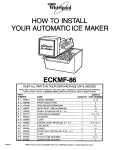
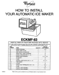
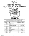
HOW TO INSTALL
YOUR AUTOMATIC ICE MAKER
ECKMF-831
KEEP ALL PARTS IN THEIR OWN PACKAGE UNTIL NEEDED
PARTS ARE LISTED BY STEPS IN WHICH THEY ARE USED. ARRANGE IN ORDER BEFORE STARTINC
INSTALLATION. REFER TO SERVICE PARTS LIST FOR INDIVIDUAL REPLACEMENT PARTS.
1
#2
#3
WIRING ASSEMBLY
WATER TUBE FITTING
GRAY SEALER (PERMAGUM)
USED IN
STEP NUMBER
4.12
1
1
3
3
#4
WATER INLET TUBE (ALUMINUM)
1
12
#5
SCREW. STAINLESS
1
14
#6
WATER VALVE ASSEMBLY
1
#7
#0
#9
ICE BUCKET
CLAMP
SCREWS, SHEET METAL (NO. 8 x ‘h”)
1
1
4
5. 6. 7. 8, 9
14
#lO
TUBE INSERT
1
11
#ll
CLAMPS
2
10
#12
#13
SCREW, SELF TAPPING (NO. 8-32 x
CLAMP
2
1
8, 9
10
#14
PLASTIC TUBE ASSEMBLY
1
6, 11
#15
COPPER TUBE ASSEMBLY
1
7
PART
NUMBER
#1
I
I
I
1108158
NAME
Water hook-up
QUANTITY
parts available
(NO. 8 x
l/2”)
from your Whirlpool
l/2”)
dealer
or local hardware
11
9, 10, 11
store.
Installation
These ~nstrucl~ons cover models with and wIthout a condenser
on the back of the cabinet.
See lll”strat1ons
below and
follow InstructIons
that apply to your model
coil
Tools and Other Items You Will Need
Water Hook Up
TOOIS
1 -Phllllps
head screwdriver
1 -Plws
l--‘/4”
nut driver
or
V flat blade screwdriver
Plastic Tube
11 Connection
-
1 Unplug
Electric
From Outlet
Steps
(Mater&
needed, not Included I” Ice Maker KII )
1%” 0 D. Copper Tubing-See
step 2 (back page)
for length.
1 -Shut-off
Valve-K
outlet
1 -Tube
Umon--1/e”
x ‘(4”
1 Remove 2 Screws
.
for WS~)
YQ.-.-
’
Remove
Water
FIII Cover
03 Install
Water Tube
&tall
Wiring Harness
1
Place Clamp onto Inlet
tube.
Place lube insert I” end
of tube and slide lnto
bnkl tube, tIghten clamp.
NOTE, Excess tube can
be cul off, be sure to
allow lone to 90 inlo tube
lor full lenglh of insert
(save
Remove Plugs and Cover
Freezer Wall.
12 from
Plug
Remove wlnng hole cover. Pull mserl pad from
cabhnet hole and place around wres.
Push wwng harness #l lnlo hole. being wre
grommet
seals flush to prevenl air entry
Connect
plug llrmly Into receptacle
Roule w,res behlnd condenser
Coils If present
14 Attach
INSTALL WATER VALVE
15
Wire
10 Attach
and Waler
Connect
terminals
valve w,nng plug onto
on valve coil.
tks
l!f
Tube Clamps -
Altach plaslic water lube
assembly
#14. Push tubmg Into
valve and tighten nylon nut (not
IOO light) onto valve threads
Tighten hose
Connector
of
copper lube lo
water valve
being sure to
point tube
straighl
up.
Attach Ground Wire (Green Wire)
with Self Tapping Screw #12.
Attach Valve
and clamp
with
wth Sell Tapping Screw
Sheet Metal Screw #9
#12
Ice Maker to Freezer Wall
Connect Ice-Maker
To Water (Contd.)
OFF shutoff valve on the water pipe. You are now
ready to connect other end of %-inch copper tubing
to inlet tube or water valve on back of refrigerator.
1.
Find a %-inch to 1-inch vertical COLD water pipe near
the refrigerator. (Horizontal pipe will work.. but extra
precautions must be taken.) (See * in Step 4.) Connect to unsoftened water line If possible.
2.
Measure from inlet on rear of refrigerator to water pipe,
Add 7 feet to allow for moving refrigerator for cleaning,
This is the length of %-inch O.D. copper tubing you
will need for the job (length from inlet tube to water
pipe PLUS 7 feet). Be sure both ends of copper tubing
are cut square.
3.
4.
5.
3
Assemble compression nuts on tubing as shown in
diagram. Insert ends of tubing into connector and
tighten compression nuts. Be sure ends of tubing are
squarely in connector as far as they will go. Do not
ovet-tiqhten.
’
XI” TUBE TO
SHUTOFF VALVE
Turn OFF main water supply. Turn ON nearest faucet
long enough to clear line of water.
Using a grounded drill, drill a ‘%-inch hole in the
vertical cold water pipe you have selected. Use of
self piercing valve may lead to flow problems in
the future. Some water almost always remains in
pipes. If it enters the drill, it can cause lethal shock.
BE SURE YOUR DRILL IS GROUNDED.
Fasten a separate ground wire from drill to a good
ground that complies to local electrical codes. (If in
doubt, consult a licensed electrician.)
UNLESS
PROPER GROUNDING IS FOLLOWED, YOU ARE
NOT PROTECTED AGAINST SEVERE OR LETHAL
SHOCK.
*If you must use a horizontal
pipe, take extra
precautions:
Drill on the top or side of the pipe, not bottom.
This helps keep water away from the drill. Also, it
keeps normal sediment from collecting in the valve.
Fasten shutoff valve to cold water pipe with pipe
clamp. Be sureinletend is solidly in the %-inch drilled
hole in the water pipe and that washer is under the
pipe clamp. Tighten packing nut. Tighten the pipe
clamp screws carefully and evenly so washer makes
a watertight connection. Do not overtighten or you
may crush copper tubing, especially if soft copper
tubing is used. Now you are ready to connect the
copper tubing.
PlPE CLAM,,
I,
INLET END
VERTICAL
OUTLET
E&
CONNECTOR
SLEEVE
NUT
UNION.
WATER VALVE TUBE
Step 7
8.
Turn shutoff valve on. TIGHTEN
TIONS OR NUTS THAT LEAK.
9.
Copper tubing may now be fastened to baseboard.
IO.
The Ice Maker has a built-in water strainer on the inlet
side of the water valve. Use a second water strainer
when local water conditions require periodic cleaning
or a well is your source of water. The strainer can be
installed in the %-inch water line.
11.
Water pressure should not be below (15 %.I.) or
above (125 P.S.I.). If problem occurs call your Utility
Company.
16 Plug
ANY CONNEC-
in your refrigerator
, /WASHER
SHUTOFF
SL&E
-NUT
1 Step 5 and 6
6.
7.
Slip compression nut and compression sleeve on
copper tubing as shown in diagram. Insert end of
tubing into outlet end squarely as far as it will go.
Screw compression nut to outlet end with adjustable
wrench. Do not overtighten. Turn ON main water
supply and flush out tubing until water is clear. Turn
IMPORTANT:
It may take up to 24 hours for your Ice Maker to begin
producing
ice crescents.
To enjoy your Ice Maker most PLEASE READ CAREFULLY THE ICE MAKER SECTION OF YOUR USE AND
CARE GUIDE.