1
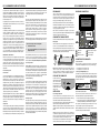
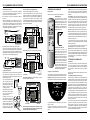
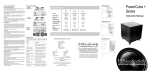
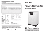
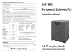
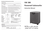
RS-10 SUBWOOFER USER INSTRUCTIONS
CARE AND MAINTENANCE
If you play the speakers with the grilles off exercise great care.
NEVER touch the drive units which are easily damaged.
The loudspeaker cabinets can be cleaned with a damp cloth or with
a spray furniture polish and a soft cloth. Apply the spray sparingly
to the cloth and then polish the cabinet. Never apply spray directly
to the cabinet.
GUARANTEE & SERVICE
In the unlikely even that your unit develops a fault you should
return it to your Wharfedale dealer using the original packing to
ensure safe shipping.
The terms of your guarantee may vary in different countries but in
all cases the guarantee excludes:
All damage caused through accident, misuse, wear and tear,
neglect, incorrect installation, adjustment or repair by
unauthorised personnel.
Liability for damage or loss occurring in transit to or from the
purchaser.
Wharfedale will not be liable for any consequential damage, loss
or injury, arising from or in conjunction with this equipment.
AUTHORISED SERVICE CENTRES
UK
USA
CANADA
IAG Service Centre
Unit 4,. St Margaret’s Way
Stukeley Meadows Industrial
Estate
Huntingdon
Cambs
PE29 6EB
England
IAG America, Inc.
15 Walpole Park
South
Walpole
MA 02081
Korbon Trading Ltd
6800 Kitimat Road
Units 19-20
Mississauga
Ontario
Tel: +1 905 567 1920
RS-10 Subwoofer
Instruction Manual
For information on other authorised service centres worldwide contact
Wharfedale International in the U.K.
A worldwide distributor list is available on the Wharfedale website:
www.wharfedale.co.uk
The name ‘WHARFEDALE' is a registered trademark of Wharfedale
International Ltd.
Wharfedale has a policy of continuous product development and reserves
the right to change specification without notice.
Wharfedale is a member of the International Audio Group.
COMPLIANCE
This Wharfedale product complies with the relevant clauses enshrined in the following standards and directives in force at the time of the
introduction of the product.
!
EU Directives: 89/336/EC, 72/23/EEC: Safety: EN60065 (CB Scheme): Emissions: EN55013, EN61000 Immunity: EN55020:2002.
!
USA: UL 6500:2002. Approved under the verification provision of FCC Part 15 as a Class B Digital Device.
!
CANADA: CAN/CSA-E60065-00
Wharfedale International Ltd, IAG House, Sovereign Court,
Ermine Business Park, Huntingdon, Cambs PE29 6XU, England.
BRITAIN'S MOST FAMOUS LOUDSPEAKERS
RS-10 SUBWOOFER USER INSTRUCTIONS
IMPORTANT SAFETY INFORMATION
Read these instructions.
Keep these instructions.
Heed all warnings.
Follow all instructions.
Do not use this apparatus near water.
Clean only with dry cloth.
Do not block any ventilation openings.
Install in accordance with the manufacturer's instructions.
Do not install near any heat sources such as radiators, heat registers,
stoves, or other apparatus (including amplifiers) that produce heat.
RS-10 SUBWOOFER USER INSTRUCTIONS
harmful interference to radio communications. However, there is no
guarantee that interference will not occur in a particular installation. If
this equipment does cause harmful interference to radio or television
reception, which can be determined by turning the equipment off and on,
the user is encouraged to try to correct the interference by one or more of
the following measures:
!
!
!
!
Do not defeat the safety purpose of the polarized or grounding type plug.
A polarized plug has two blades with one wider than the other. A
grounding type plug has two blades and a third grounding prong. The
wider blade or the third prong are provided for your safety. If the
provided plug does not fit into your outlet, consult an electrician for
replacement of the obsolete outlet.
Use only with a cart, stand, tripod, bracket, or table
specified by the manufacturer, or sold with the apparatus.
When a cart is used, use caution when moving the cart/
apparatus combination to avoid injury from tip-over.
Warning: To reduce the risk of fire or electrical shock, do not expose this
product to rain or moisture. The product must not be exposed to
dripping and splashing and no object filled with liquids such as a vase of
flowers should be placed on the product.
No naked flame sources such as candles should be placed on the
product.
Caution: Changes or modifications not expressly approved by the
manufacturer could void the user's authority to operate this device.
Warning: The mains power switch for this appliance is located on the
rear panel. To permit free access to this switch, the apparatus must be
located in an open area without any obstructions.
NOTE: This equipment has been tested and found to comply with the
limits for a Class B digital device, pursuant to part 15 of the FCC Rules.
These limits are designed to provide reasonable protection against
harmful interference in a residential installation. This equipment
generates, uses and can radiate radio frequency energy and, if not
installed and used in accordance with the instructions, may cause
Possible Cause
Sound lacks bass content
Bass reproduction indistinct
Front loudspeakers out of phase.
Subwoofer not switched on; Subwoofer phase incorrect; Subwoofer crossover control too low
Excessive bass distortion at low volumes
Subwoofer level set too high; LFE level set too high; Subwoofer incorrectly wired
CAUTION!
Excessive or distorted bass at high levels
System level set too high; Bass control set too high; Speakers too close to room corners
RISK OF ELECTRIC SHOCK
DO NOT OPEN
Distorted or rattling sounds at high levels
System level too high; Objects on speakers/subwoofer; Objects too close to subwoofer
SW 250 will not respond to commands
Handset batteries weak; handset too far away; line of sight is impeded
Popping or thumping from the subwoofer
System level set high; Subwoofer level set too high; LFE level set too high
Indistinct sound; Poor localisation of
effects. Poor localisation of dialogue
One or more loudspeakers is out of phase
(Read the manual for correct connection procedure)
Television picture colour is distorted
Subwoofer too close to TV. (Switch off system and TV. Move units away. Leave 15 mins. Switch on)
This symbol indicates that there are important
operating and maintenance instructions in the
literature accompanying this unit.
Unplug this apparatus during lightning storms or when unused for long
periods of time.
Symptom
System not switched on; Speaker cables shorting terminals out; Wrong source selected
ADVERTISSEMENT: RISQUE DE CHOC ELECTRIQUENE PAS OUVRIR
Use only attachments/accessories specified by the manufacturer.
If your system is not working properly please work through this checklist before returning a unit to your dealer. Before investigating a problem, always
switch off the system at the mains.
No Sound
TO REDUCE THE RISK OF ELECTRIC SHOCK
DO NOT REMOVE COVER (OR BACK)
NO USER-REMOVEABLE PARTS INSIDE
REFER SERVICING TO QUALIFIED PERSONNEL
Protect the power cord from being walked on or pinched, particularly at
plugs, convenience receptacles, and the point where they exit from the
apparatus.
Refer all servicing to qualified service personnel. Servicing is required
when the apparatus has been damaged in any way, such as powersupply cord or plug is damaged, liquid has been spilled or objects have
fallen into the apparatus, the apparatus has been exposed to rain or
moisture, does not operate normally, or has been dropped.
Reorient or relocate the receiving antenna.
Increase the separation between the equipment and receiver.
Connect the equipment into an outlet on a circuit different from that
to which the receiver is connected.
Consult the dealer or an experienced radio/TV technician for help.
TROUBLESHOOTING
This symbol indicates that dangerous voltage
constituting a risk of electric shock is present within
this unit.
ESSENTIAL INFORMATION FOR UK USERS
The power cord on your subwoofer may be supplied with a plug
incorporating a fuse, the value of which is indicated on the pin face of the
plug. Should the fuse need to be replaced, an ASTA or BSI approved
BS1362 fuse must be used of the same rating. If the plug is cut off it must
NOT be re-used. Dispose of any such plug safely. There is a danger of
electric shock if a cut-off plug is inserted into a mains socket.
The wires in the mains lead are coloured in accordance with the following
code: Green and Yellow - Earth: Blue - Neutral: Brown - Live.
As the colours of the wires in the mains lead may not correspond with the
markings identifying the terminals in the replacement mains plug,
proceed as follows:
The wire coloured Blue must be connected to the terminal marked with
EARTH
the letter ‘N’ or coloured Black. The wire
(GREEN/YELLOW)
coloured Brown must be connected to
the terminal marked with the letter ‘L’ or
FUSE
coloured Red. The wire coloured Green
and Yellow must be connected to the
terminal marked with the letter ‘E’,or
coloured Green, or Green and Yellow, or
NEUTRAL
LIVE
marked with the Earth symbol
(BLUE)
(BROWN)
SPECIFICATIONS
Model
Format
Drive Unit
Amplifier Power
Line Input Sensitivity
Averaged Max. O/P (@ 1M)
Frequency Response
(Boundary Position)
Low Pass Filter Frequencies
Phase Adjustment
Dimensions (H x W x D) mm
Height on Feet mm
RS-10 .SUBWOOFER
Powered Subwoofer
250 mm kevlar cone
250W
250mV for 200W
107 dB
30 Hz – 95Hz
35 Hz – 85 Hz
(6 x 10Hz steps)
Switchable 0º - 180º
370 x 546 x 295
400
of the Volume Control on your amplifier is NOT a reliable guide as to ‘how
loud’ your equipment will play. Allow your system ample ‘headroom’.
GENERAL GUIDANCE
DO NOT connect the mains power to any signal input terminal.
DO NOT change any connections without first switching off the power to
all the components in your AV system.
ALWAYS turn down the system master volume control before turning
the equipment on or off.
DO NOT use your amplifier at its maximum volume setting. The resulting
distortion may damage your loudspeakers and subwoofer. The position
Do not operate your subwoofer closer than 450mm from the TV to avoid
distorting the colour picture. if this occurs, switch the TV set off. After 15
minutes switch on again: colour balance should now be restored.
To minimise hum and mains interference ensure that low level (line level)
signal cables are well screened. Avoid routing low-level signal cables
close to or parallel with mains power wiring.
Page 2
Page 7
RS-10 SUBWOOFER USER INSTRUCTIONS
The subwoofer has to blend with the main speakers: if you place the
subwoofer where it amplifies the irregularities of the room or the main
speakers the result will be bloated, coloured bass. If acoustic guitar and
male voice sounds coloured when the subwoofer is operating and less
coloured when in standby, you need to address the positioning first
before adjusting any controls
The optimal position for the subwoofer is 50mm from a rear wall, i.e.
with the amplifier heatsink 10mm from the wall. On no account should
the heatsink touch the wall.
Loudspeaker Phasing
It is absolutely essential for all speakers to be connected correctly with
the RED + and BLACK - terminals of the speakers connected to the
corresponding RED + and BLACK - terminals of the AV amplifier (‘in
phase’). This is particularly important if speakers are bi-wired. If the
sound is not as clear as it could be, check all speaker connections
carefully before proceeding further. Correctly connected front channel
loudspeakers give a definite centre sound source with full bodied tenor
and bass registers.In Stereo, if there is a doubt about the way the
loudspeakers are connected, check their phasing by playing a mono
source - the sound should appear from a point midway between the two
loudspeakers. If this position is indefinite, reverse the connections to
one of the loudspeakers. Correctly connected loudspeakers give a
definite centre sound source with fuller bodied tenor and bass registers.
Setting the Phase of the Subwoofer
Phase at very low frequencies is not straightforward to detect. Initially
we suggest you temporarily set the low pass filter to ‘off’ and the phase
to 0º and play some bass heavy music in Stereo through the main
speakers and the subwoofer. From the listening position, switch the
phase between 0º and 180º. The setting which appears to give the greater
bass output is correct. Now follow the instructions below for setting the
low pass filter.
Home Cinema Systems
Low Pass Filter
If you are using a digital AV processor the initial setting should be ‘OFF’
as the processor will have its own bass management system. Most
digital AV Processors ask you to specify the size of speakers in the
various channels. These are usually ‘Large’ or ‘Small’. This sets the bass
management for the system. Unless your loudspeakers are large floor
standing units, you should choose 'Small' for the Front channels, as the
subwoofer is going to be better at providing clean, deep bass. Choose
'Small' for the surround channels and also for the Centre channel, so that
any bass from these channels will be directed to the subwoofer. Set the
‘Subwoofer’ option on the processor to 'On’ or 'Yes'.
After experimenting with various sources you may need to adjust the LPF
settings. The goal is to ensure the subwoofer blends seamlessly into the
sound stage. Setting the subwoofer to Standby should reduce the bass
extension, not change the bass level - as always personal taste plays an
important part.
Setting levels
Once the loudspeaker settings have been finalised, put the AV amplifier
into its “Test” mode (see instructions supplied with your processor.)
Adjust the levels until all channels are reproduced at equal loudness.
When adjusting the subwoofer output level avoid setting too high a level
or you will swamp the sound with bass which be tiring to listen to and
RS-10 SUBWOOFER USER INSTRUCTIONS
may limit the subwoofer’s ability to respond to large bass transients. Set
a sensible level going into the subwoofer from the processor. The
volume display should be around 50 at normal listening levels.
LFE
This channel was originally an additional bass channel with its own
dedicated subwoofer. In practice however, if any speakers are set to
‘Small’, the LFE channel is combined with the bass from those channels
and fed into the subwoofer. When you set the LFE level from your AV
processor, use care as the LFE channel contains powerful low
frequencies which, although normal in a cinema, may overload a
domestic subwoofer. If, during a programme, you hear popping or
thumping noises from the subwoofer, turn the AV Processor volume
level down and back off the LFE level. If this does not cure the problem,
lower the subwoofer volume level.
Note: If any channels are set to ‘Small’ the subwoofer must be on when
the system is playing otherwise there will be reduced bass , and no LFE.
PRELIMINARIES
REAR PANEL CONNECTIONS
Open the carton and remove all the top packing pieces. Lift the
subwoofer out taking care not to damage the cabinet. When lifting the
unit from the carton support it from the bottom. DO NOT attempt to lift
the subwoofer out of the carton using the polythene bag. The unit is
heavy; if you cannot manage it easily, get someone to assist you.
The amplifier heatsink
must be 10mm away
from the wall
After removing the subwoofer from the carton, remove the plastic bag.
Retain the packing materials for future use or return them to your dealer.
If you decide not to keep the packing, please dispose of it having regard
to any recycling regulations in your area.
Please retain the user manual and the purchase receipt for future
reference. If you transfer this equipment to a third party, please ensure all
the instructions are passed on with the product.
INPUT
RS 10 SUBWOOFER
OUTPUT
WHARFEDALE INTERNA TIONAL LTD,HUNTINGDON, UNITED KINGDOM
LEFT
RIGHT
LINE LEVEL
CHANGING THE SUBWOOFER FEET
CAUTION
RISK OF ELECTRIC SHOCK
DO NOT OPEN
Fitting Spikes
Subwoofer Settings for RS-10 loudspeakers.
!
!
Set all channels to ‘small’
If you are using a digital AV processor the subwoofer LPF
setting should be 85Hz.
Low Pass Filter: The low pass filter should be set having regard to the
size and low frequency extension of the main speakers. The role of the
subwoofer is to extend the bass response of the system not to increase
the overall bass level. If the loudspeakers are large the LPF should be set
low, a value around 45-55 Hz is a good place to start. With smaller
speakers this can be increased, up to 85Hz for very small bookshelf
units. As always the final value is determined by listening.
Low-level Listening
Our ears are far more sensitive to midrange frequencies (2-5 kHz) than
bass frequencies. Very low bass and especially percussive bass is ‘felt’
rather than heard. At low sound levels bass frequencies appear to
attenuate faster than midrange and treble. As the level increases this
bass roll-off decreases. Occasionally we may wish to listen to a normally
loud piece of music at a low level but with retention of the bass
information. There may be a case for assigning a preset for low level
listening where the subwoofer volume is set somewhat higher and the
LPF is set a little lower - as always this is for individual judgement.
Testing the system
The simplest way to test the system is to play, at a moderate level, music
with deep consistent bass. Switching the subwoofer in and out of
Standby should cause change of the depth of bass, and the ambience will
also alter. If there is a significant change in bass volume, or a noticeable
step in the bass response, or an increase in coloration when the
subwoofer is playing, the setup needs to be refined further. By entering
different settings in different presets, you will be able readily to identify
the most favourable combination.
ON
OFF
Invert the subwoofer. Protect the top by placing it on a soft surface such
as a towel. Loosen each threaded washer and unscrew the rubber feet.
N2082
POWER
AC 220-240V~50Hz 400W
FUSE T4AL250V
SPEAKER LEVEL INPUTS
Mains Input
Speaker (High) Level Inputs
Mains Fuse
Line Level Outputs
Mains Power Switch
Line Level Inputs
Washer
CONNECTING THE SUBWOOFER
Power Connections
Before connecting your subwoofer check that the check that mains
voltage marked on the amplifier panel is correct for your mains supply.
Spike
Note: When using spiked feet take care not to drag the subwoofer and be
careful not to pierce objects or cables which may be hidden under
carpets, etc. Spikes are not suitable for use with stone floors and can
cause damage to wood floors, so consider carefully before using them
LEVELLING THE SUBWOOFER
Screw each foot in and out
until the subwoofer is level
(side to side and front to
back) and firmly supported
Tighten the washers on the
feet with a wrench to lock
them in position.
! 230 volt products - 220 volts to 240 volts
! 115 volt products - 110 volts to 120 volts
Connecting to a Digital AV processor
If your AV processor has a line level or LFE subwoofer output you should
use this connection. You will need to purchase a single screened RCA
phono lead from your dealer. Connect this lead to the Left line input of the
Subwoofer as shown below.
INPUT
OUTPUT
SUBWOOFER
OUTPUT
AV PROCESSOR
LEFT
RIGHT
LINE LEVEL
SUBWOOFER
INSTALLATION
Stereo Line Level Connections
Positioning the subwoofer
Stereo line level connections will be necessary where there is no
dedicated single subwoofer output, but where there is either :
The RS-10 subwoofer uses a rear-firing bass driver. For the unit to
perform at its best it should be placed with the heatsink fins 10 mm away
from a wall. The bass driver will now be 50mm from the wall.
The rear wall should be smooth, solid and free from vibration. The floor
under the subwoofer should be firm and free from rattles.
Caution: Do not place the subwoofer touching the wall. There must be air
circulation around the unit and the mains switch should be accessible at
all times.
!
!
A stereo subwoofer line output or a separate preamp output.
In stereo systems where there is a suitable preamplifier line output,
or if an integrated amplifier, a pre/main link that can be separated.
The output must be controlled by the system volume control - a tape
output is not suitable. If you are in doubt, consult your dealer.
Stereo Connections: Connect a stereo RCA phono cable from the line
output of the preamp to the Subwoofer line inputs.
Although the unit may be sited by either the rear or side walls, we
recommend that is placed in front of the listener central to the listening
position. To avoid excessive booming and coloration we suggest that
you operate the subwoofer at least 500mm away from corners.
There should be a line of sight between the listener and the front of the
subwoofer otherwise the remote functions will not be operable.
Page 6
RIGHT
LEFT
SERIAL No:
Remove the threaded washers and replace them on the spikes. Screw a
spike part-way into each hole and hand-tighten the washer. When all
four feet have been fitted, stand the subwoofer upright.
After experimenting with various sources you may need to adjust the
LPF. If you choose too low a setting there will be a ‘hole’ in the bass
response. Choose too high a frequency and the bass will appear bloated
with loss of definition. The optimal setting for RS-10 speakers is 85Hz.
Stereo Reproduction
!
The subwoofer is fitted with rubber feet. A set of spikes is also provided.
Page 3
INPUT
OUTPUT
LEFT
Preamp Output
AV PROCESSOR/STEREO PREAMP
RIGHT
LINE LEVEL
SUBWOOFER
RS-10 SUBWOOFER USER INSTRUCTIONS
Pre Out - Main In Connections
If you use a separate stereo pre and power amplifier, or an amplifier
where the pre and main amplifier can be separated, connect the subwoofer as shown. There are two alternative methods.
A: You will need two screened RCA ‘Y’ adaptors and two single RCA
phono cables.
Remove the Pre-Main links on your amplifier. Connect the socket
(common) of an RCA ‘Y’ adaptor to one of the mono cables. Connect one
leg of the ‘Y’ adaptor to the Left Channel Pre Out socket on the amplifier
and the other leg to the Left Channel Main In socket. Connect the
remaining plug on this combination to the Left Channel Line Level Input
on the subwoofer. Repeat this for the Right Channel.
RS-10 SUBWOOFER USER INSTRUCTIONS
There are two methods of connecting the subwoofer:
OPERATING YOUR SUBWOOFER
A: Ensure the Front loudspeakers are correctly connected.
Remote Handset
Using one of the additional twin core cables, connect the Left Speaker
Terminals on the sub bass unit to the Front Left speaker terminals on the
amplifier. Connect the Red (+) speaker terminal on the amplifier to the
Red (+) terminal on the subwoofer. Connect the Black (-) speaker
terminal on the amplifier to the Black (-) terminal on the subwoofer. Now
connect the Right Speaker terminals on the subwoofer to the Front Right
speaker terminals on the amplifier.
All control functions are carried out using the remote handset.
AMPLIFIER
(x2)
MAIN PRE
IN
OUT
L
R
Installing batteries
The handset operates on two LR6 (AA)
batteries which are supplied The battery
compartment is located at the rear of the
handset. Unwrap the batteries and slide the
cover off the handset. Place the batteries in
the handset, the correct orientation is shown
on the diagram. When the batteries are
installed, replace the cover.
SUBWOOFER CONTROL
FRONT
RIGHT
Volume: Press the Volume + key to increase the volume level. Press the
Volume - key to decrease the volume level of the subwoofer. The volume
range on the front panel display varies from 00 (minimum) to 99
(maximum).
OUTPUT
RIGHT
LEFT
LEFT
AA
RIGHT
AA
To change from one preset to another, press a preset key on the remote
for less than 3 seconds to recall the settings of that preset. The display
will show the preset number:
LINE LEVEL
SUBWOOFER
FRONT RIGHT
LEFT
FRONT LEFT
RIGHT
SPEAKER LEVEL INPUTS
Connect a Stereo cable from the Line Level Inputs of the subwoofer to
the Pre Out sockets of the amplifier. Now connect a second Stereo cable
from the Line Level Outputs of the sub-woofer to the Main In sockets of
the amplifier. Make sure that the Right and Left Channels are not mixed
up! The sub-woofer is now inserted within the system loop.
Switching on the Subwoofer
L
PRE
OUT
Check that all the connections to the
subwoofer have been properly made and
that the system volume control is at
minimum. Plug the supplied power cord into
the mains socket on the rear panel. Plug the
mains plug into the wall socket and switch
the power on. Now switch the subwoofer on
with the rest of your system. The subwoofer
on/off switch has a rocker action; press the
upper part to switch the equipment on and
the lower part to switch it off. When switched
on the light above the power switch will glow
and the subwoofer will be operational.
B: Alternatively you may connect the subwoofer to the Front speakers.
AMPLIFIER
MAIN
IN
FRONT
INPUT
RIGHT
AMPLIFIER
LEFT
OUTPUT
R
LEFT
RIGHT
LEFT
RIGHT
LINE LEVEL
SUBWOOFER
LEFT
RIGHT
SPEAKER LEVEL INPUTS
Speaker Level Connections
The high level Speaker connections should be used only if your amplifier
does not have a line level subwoofer output. In this connection the
subwoofer is fed together with the Front loudspeakers. For this you will
need two extra twin core cables.
Choose a good quality audio speaker
cable of reasonable gauge. Avoid
using cheap ‘bell’ or ‘zip’ cables. Audio
speaker cable has a polarity stripe or
rib along one conductor to simplify
connecting your speakers.
Operation - Controls and Functions
SUBWOOFER
FRONT LEFT
FRONT RIGHT
If your speakers are bi-wired: You should ensure that you connect the
subwoofer to the BASS terminals ONLY.
AMPLIFIER
Control functions are carried out using the remote handset. To operate,
the handset must be point at the subwoofer and be in direct line of sight.
LOW PASS FILTER SELECT
RIGHT
35Hz
LEFT
45Hz
55Hz
65Hz
75Hz
OFF
85Hz
MEMORY
VOL UME
PHA SE
0
2
1
3
LEFT
4
RIGHT
SPEAKER LEVEL INPUTS
SUBWOOFER
FRONT RIGHT
FRONT LEFT
When routing any cables to loudspeakers do not run them across open
floor spaces where they may cause danger to people and pets. Route
them safely, around room boundaries if necessary.
Page 4
SETTING UP YOUR SUBWOOFER
General Notes
Your subwoofer is most likely to be used with two typical programme
sources, music and movies. The setup for these two very different
sources may be different if best results are to be achieved. Please read
these setup notes in conjunction with your processor and speaker
manuals.
All setting up of the subwoofer should be performed with tone controls
and filters set ‘flat’.
Listening Rooms and Subwoofer Positioning:
To help locate standing waves in your listening room, one idea is to sit in
the listening seat and recruit a friend with a deep voice to speak as he
moves around the area where you propose to site your subwoofer - you
will soon find out where not to site it! Where the voice sounds most
natural is a good place to start.
180
POWER
Note: When brought out of standby for the first time, the unit will display
the factory presets. Thereafter, bringing the unit out of standby will
revert it to the operational state last used. If you switch the power on and
off at the rear panel while the unit is in standby, the unit will power up to a
normal operating state (i.e. not in standby). To enter standby, again
press the Standby key.
Listening rooms are not ideal. Most rooms are reverberant with some
parallel walls. Because of room geometry and construction there will be
areas with severe peaks at some frequencies and severe troughs at
others. These peaks and troughs are called ‘standing waves’ and if you
site loudspeakers in such areas the response will be highly non-linear.
With subwoofers this situation is exacerbated by the fact that it is easier
to treat high frequency irregularities by the use of drapes, soft
furnishings etc., but very hard to do the same at bass frequencies due to
the very long wavelengths - at 40 Hz the wavelength is almost 9 metres!
Standby: The Standby key brings the subwoofer in and out of Standby.
The drawing below shows a typical front panel display during operation.
FRONT
Split the cable at each end to a depth of
25mm. Strip about 7mm of insulation
from each end and lightly twist to
gather the wire strands.
The Speaker Level connectors are
screw terminals located on the control
panel. Unscrew a terminal and insert
the cable into the hole at the base. Retighten the terminal securely. Make
sure that the terminal grips the bare
wire and there are no loose strands
which could touch adjacent terminals.
If you select a preset and then alter any aspect of the setup, the preset
light will extinguish (as the setup no longer matches the preset).
SUBWOOFER
B: You will need two stereo (or four single) screened RCA cables.
Phase: This key toggles the subwoofer between 0º and 180º phase shift.
Presets: Four different settings of level, frequency and phase can be
stored. Pressing and holding any of the preset keys on the remote for 3
seconds will cause the current settings to be stored in that preset. The
display will show the preset number then flash the preset number once
to show it has stored the preset.
LEFT
INPUT
AMPLIFIER
Low Pass Filters: Pressing the appropriate filter key will select the
frequency at which the subwoofer rolls off. The filter has steps at Off and
35Hz-85Hz in 10 Hz increments. When ‘OFF’ is selected the subwoofer
operates over its full designed range. Pressing other keys lowers the
maximum operating frequency. The Low Pass Filter value should be
chosen having regard to the nature of the Front speakers and
programme material. Follow the Setup Notes on Page 6 and the
instruction manual of your AV processor (if used) for more guidance.
The preset light will not light if no preset has been set up or if a preset
has been over-ridden.
In Standby mode all the lights on the subwoofer front panel are
extinguished. The rear panel light remains on to show the unit is
powered.
The low frequency response of the subwoofer and its blend with the main
loudspeakers is greatly affected by positioning. Although bass is
enhanced by walls or corners, so often is coloration. As the drive unit
faces rearward, the wall will influence the sound. The wall should be
smooth and solid and ideally, nonr-everberant. The surface under the
subwoofer should be stable and unobstructed. I
Page 5