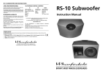
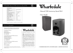
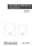
1
RS-10
SPECIFICATIONS
Bass/mid unit
Tweeter
Rec. Amplifier
Nominal Impedance
A/V shielding
Sensitivity (1W @ 1M)
Freq Range (-6dB)
HF limit (-10db)
Crossover Frequency
Freq (Fb)
Size (H x W x D)
Height on shelf stand
Height on floor stand
Carton Quantity
Included Accessories
Optional Accessories
RS-10 Satellite
100mm (4") kevlar cone x 2
25mm textile
20 - 120 w
6 Ohms*
Yes
87db
85Hz - 24kHz
44Khz
2.8Khz
95Hz
600 mm x 127 mm x 95 mm
615 mm
1225 mm
Pair
2 x wall brackets
RS-10 Centre
100mm (4") kevlar cone x 2
25mm textile
20 - 120 w
6 Ohms*
Yes
87db
85Hz - 24kHz
44Khz
2.8Khz
95Hz
127 mm x 600 mm x 95 mm
137 mm
Home Cinema
Loudspeaker System
Instruction Manual
Single
1 x wall bracket
1 x shelf stand
Table Stands (pair pack)
Floor Stands (pair pack)
* Compatible with amplifiers requiring 8 Ohm loudspeakers.
Wharfedale reserves the right to change specification without notice.
*Table stands shown are optional extras
Wharfedale International Ltd., IAG House, Sovereign Court, Ermine Business Park, Huntingdon, Cambs PE29 6XU, England.
Tel:+44 (0)1480 447700 www.wharfedale.co.uk
Wharfedale is a member of the International Audio Group.
BRITAIN'S MOST FAMOUS LOUDSPEAKERS
Delay Settings
subwoofer. When you set the LFE level at your AV processor, use
care as the powerful low frequencies can overload domestic
loudspeakers. If you hear popping or thumping noises coming
from the front loudspeakers or subwoofer, immediately turn the
AV Processor's volume level down and then back off the LFE level.
This should cure the problem. If it does not, back off the volume
level at the subwoofer. Please read the relevant sections of your
AV amplifier manual and familiarise yourself with the various
issues. If you are unsure, consult your dealer for help.
Many AV processors feature delay settings. The purpose of delay
is to enable surround and dialogue information to arrive at the
listener’s ears at the same time as the Front channels, even when
the listening seat is in a non-ideal position.
Rear Delay: If the listening position is equidistant from the
Front and Rear speakers, a low delay setting should be set. The
closer the listener is to the Rear speakers the higher should be the
delay setting used,
Phase
A Home Theatre system should have a precise front stage, a
diffuse rear stage and good localisation of dialogue. If the
colours on the loudspeaker terminals do not correspond with
those on the amplifier, the sound will appear poorly focused or
‘out of phase’. For this reason it is essential that the speakers are
connected according to the wiring diagrams in this manual.
Centre Delay: If the Centre speaker is level with (or slightly
behind) the Front speakers, set the delay to zero. If the Centre
speaker is forward of the Front speakers, increase the delay.
LFE
In domestic systems the LFE channel typically feeds into the
PRELIMINARIES
UNPACKING YOUR LOUDSPEAKERS
After taking out the top-most packing piece, lift the
loudspeakers and accessories from the carton and remove
all the polythene bags.
The contents of each carton are as follows:
RS-10 Satellites:
!
!
Two RS-10 satellite speakers
Two wall brackets*
RS-10 Centre:
!
!
!
One RS-10 Centre speaker
One wall bracket*
One table stand with mounting hardware
Check all the items after unpacking. If any item is missing or
damaged, immediately contact your Wharfedale dealer.
Retain the packaging. If you decide to dispose of the
packing, follow all recycling regulations in your area.
CARE AND SERVICE
CARE
Wharfedale will not be liable for any consequential damage, loss
or injury, arising from or in conjunction with this equipment.
The cabinets can be occasionally wiped with a damp (not wet)
cloth. Spray polishes can be used but they must not be sprayed
onto the grilles or drive units. Spray a very small amount of
polish onto a cleaning cloth not the loudspeaker.
The warranty on this product if it is sold outside the United
Kingdom shall comply with applicable law and shall be the sole
responsibility of the distributor that supplied this product.
WARRANTY IN THE UK
Service Addresses, UK & USA
In the unlikely even that your unit develops a fault you should
return it to your Wharfedale dealer using the original packing to
ensure safe shipping. The terms of your warranty may vary in
different countries but in all cases the guarantee excludes:
IAG Service Centre
Unit 4, St Margaret’s Way
Stukeley Meadows Industrial Estate
Huntingdon, Cambs,
PE29 6EB
England
Tel:+44 (0)1480 452561
Fax: +44 (0)1480 13403
All damage caused through accident, misuse, wear and tear,
neglect, incorrect installation, adjustment or repair by
unauthorised personnel. Liability for damage or loss occurring in
transit to or from the purchaser.
IAG America, Inc.
15 Walpole Park South
Walpole
MA 02081
USA
Tel: +1 508 850 3950
Fax +1 508 850 3905
* Note: No hardware is supplied to attach wall brackets to walls.
Table stands and floor stands for the RS-10 satellites are available
as optional extras from your dealer.
Before installing this product
read all these instructions!
Before making any connections, switch the amplifier off.
When you switch on your system or change sources, set the
volume control at minimum and turn the level up
gradually.
DO NOT use your amplifier at full volume.
Ensure that all loudspeakers in the system are correctly
wired.
DO NOT subject your loudspeakers to excessive cold, heat,
humidity or sunlight.
DO NOT place heavy objects on top of loudspeakers
DO NOT connect loudspeakers to the mains supply.
DO NOT dismantle the loudspeaker. There are no user
serviceable parts inside it and you will void the warranty.
PREPARATIONS FOR INSTALLATION
Positive (+) terminal is on the left and has a Red collar. The
Negative (–) terminal is on the right and has a Black collar.
STANDS AND BRACKETS
RS-10 loudspeakers must be operated attached to wall brackets
or stands. Wall brackets are supplied for all RS-10 models and a
table stand is also supplied for the RS-10 Centre speaker.
To connect the terminals: Unscrew each terminal. Thread the
bare end of the cable through the cross-hole in the terminal
ensuring there are no loose strands. Tighten securely.
Optional table stands and floor stands for RS-10 satellites are
available in pairs from your Wharfedale dealer.
b
Use only the designed stands or brackets supplied with the units.
c
CONNECTORS AND CABLES
You will need five lengths of two core cable. The cables
connecting the Front loudspeakers should be the same length
and the cables connecting the Rear loudspeakers should also be
of equal length. We suggest you use cable designed for audio
and not general purpose ‘bell’ or ‘zip’ wire.
Loudspeaker cable is polarity coded along one edge. Split the
cable to a depth of 25mm and strip 8mm of insulation from each
wire. If the cable is stranded, twist the strands together.
Before connecting your system consider where you will place the
speakers in the room. This is particularly important if you are
wall mounting loudspeakers.
RS-10 loudspeakers have two connection terminals. The
6
1
STAND MOUNTING
WALL MOUNTING
CENTRE LOUDSPEAKER
Amplifier
Place the speaker on the stand and align the
mounting holes in the stand with the mounting
holes in the rear of the speaker.
Place a shakeproof washer on each of the supplied
screws and attach the stand to the speaker.
Remove the speaker grille
Thread the speaker cable through the recess at the
edge of the cabinet and out through the hole in the
rear of the stand.
Prepare the cable and connect the loudspeaker as
shown on Page 1. The striped or ribbed cable
should be connected to the Red (+) terminal and
the plain cable to the Black (-) terminal.
Replace the grille.
Place the speaker in position. Leave a little slack in
the cable to avoid moving the stand assembly.
FRONT LOUDSPEAKERS
BRACKET POSITIONS - FRONT AND REAR SPEAKERS
If the mounting position is higher than 1500mm it is preferable to
angle the speaker. Otherwise mount the loudspeaker vertically.
ANGLED
VERTICAL
REAR LOUDSPEAKERS
If the loudspeakers are sited behind the listener on a rear wall, it is
advisable to mount them high, around 1800mm and angled down.
Rear speakers placed on the side walls may be placed at a height of
1500mm and angled vertically or 1800mm and angled down.
Speaker
Ensure that the wall is sound and can support the weight of the
speaker. Mark off two centres 60mm apart and vertically spaced.
Drill two 6mm holes and insert suitable wall plugs. Attach the
bracket firmly to the wall with No 8 countersunk screws. Follow the
drawings to establish the correct orientation of the bracket.
60 mm
Locating
Flange
Locating
Flange
Bottom
Tongue
Bottom 60 mm
Tongue
CENTRE LOUDSPEAKER
Align the bracket horizontally such that the loudspeaker is parallel
to the wall. In all other respects the mounting procedure is identical.
60 mm
*Note: Table Stands are not supplied with the RS-10 satellites but are available as optional extras
SATELLITE SPEAKERS
Thread the stand column through the stand base.
Attach the column to the base with the four
supplied screws.
Thread the speaker cable through the slot in the
column.
Remove the grille from the loudspeaker.
Remove the four mounting screws from the base of
the speaker (circled in white in Fig.1). Retain the
screws.
Align the speaker over the column.
Attach the speaker firmly to the column using the
screws you have saved.
Prepare the cable and connect the loudspeaker as
shown on Page 1. The striped or ribbed cable
should be connected to the left Red (+) terminal
and the plain cable to the Black (-) terminal.
Replace the grille.
Lead the cable through the groove in the base of
the stand and place the speaker in its location.
Leave a little slack in the cable to avoid pulling the
stand assembly over.
Place the speaker on a soft surface.
c Holding the speaker cabinet securely,
c
b
ease the front grille off via the sides and
keep it safe.
b
Identify the keyhole slot
which is sited at the rear
centre of the speaker.
d
The keyhole slot fits
over the locating flange
which is attached to the
top of the bracket.
Remove the four mounting screws from
the base of the speaker (circled in white
in Fig.3). Retain the screws.
Thread the speaker cable through the bracket as shown.
d
Slot the speaker over the locating flange in the bracket
and then slide it into the bottom tongue of the bracket
Align the mounting holes in the bracket over the holes in
the speaker and attach the speaker firmly to the bracket
using the screws you have saved.
Prepare the cable and connect the loudspeaker as shown
on Page 1. The striped or ribbed cable should be
connected to the left Red (+) terminal and the plain
cable to the Black (-) terminal.
Replace the grille.
4
To AV
Amplifier
3
CONNECTING THE LOUDSPEAKERS
HOME THEATRE LAYOUT
POSITIONING THE FRONT SPEAKERS
RS-10 speakers must be wall or stand mounted. Their bass
extension depends on proximity to a wall, though they should be
kept out of room corners. Ideally they should be mounted 1-2
metres above the floor and 2-4 metres apart, central to the listening
position.
2 - 4 metres
>0.7metre
Listening Seat
2-4metres away
POSITIONING THE REAR SPEAKERS
The speakers should ideally be sited 600 mm-1.5 metres above the
listening position and 2.5-3.5 metres apart, central to the listener
and either on a rear wall or on either side of the listener facing
inward, but always behind the listening position.
LISTENING POSITION
POSITIONING THE CENTRE SPEAKER
The RS-10 Centre speaker
is clearly identified with the
badge horizontal to the
speaker. so make sure you
don’t use it as a satellite by
mistake!
The speaker should be on
its dedicated stand, located
TV
on a stable, flat surface to
avoid any movement of the
loudspeaker at high sound
levels. Alternatively it can
be wall mounted.
We recommend that the
RS-10 Centre is mounted
DVD
above the TV screen, with
the front grille level or
slightly in front of the screen. It may also be placed below the
screen.
The television should be positioned centrally between the
front loudspeakers and the front face of the RS-10 Centre
should ideally be in line with the front loudspeakers.
2.5 - 3.5 metres
HOME THEATRE LAYOUT
Connect each loudspeaker to the correct channel
of your AV amplifier or processor taking care to
connect the Red, Positive (+) terminal of the
speaker to the Red, Positive (+) terminal of the
speaker output terminal of the amplifier, and
similarly with the Black (–) terminal.
CENTRE
INPUT
OUTPUT
LEFT
RIGHT
LINE LEVEL
A/V
PROCESSOR
SUBWOOFER
SUBWOOFER
OUT
FRONT
L
L
C
FRONT
R
R
RIGHT
LEFT
REAR
REAR
SETTING UP YOUR HOME CINEMA
THE 5.1 HOME ENVIRONMENT
The preferred 5.1 positions are shown in the drawings below.
If you have a large room or your listening position is not central
to the side walls (as in the diagram), we recommend that you
purchase the optional table or floor stands which have been
designed to optimise the soundstage of the RS-10 system.
Placing rear speakers on opposite side walls (shown in pale grey
in the figure on the left) is acceptable in smaller rooms but is not
recommended for large rooms.
The front loudspeakers are placed on either side of the television
screen, 2 to 3 metres apart. If you are using the optional stands,
the speakers may be angled slightly inwards so they are aimed
towards the listeners.
The performance of Home Theatre systems can be enhanced by
using a pair of subwoofers.
Setting Loudspeaker Sizes
Many digital AV Processors require you to specify the size of
speakers in all channels. These are usually ‘Large’ or ‘Small’. All
the channels should be set to SMALL . This routes all the bass to
the subwoofer.
As the rear surround channels are the ‘effects’ channels the sound
should be as room filling as possible. We recommend placing the
speakers in a high position, behind the listener’s head.
Most of the dialogue comes from the centre loudspeaker. Speech
should appear to originate from the actors’ mouths. Operating
height is important. Ideally the front and centre channel speakers
should be at the same height .The front faces of the centre and
surround loudspeakers should also be in line as far as possible.
Setting Levels
Once the loudspeaker settings have been finalised, put the AV
amplifier into its “Test” mode (see instructions supplied with your
processor). Adjust the level of each channel in turn until all
channels are reproduced at equal loudness.
The system is intended for use with the RS-10 subwoofer. This
should be placed 50mm from the wall to optimise the bass
performance of the unit. (See P 3 of the subwoofer manual.)
On some programmes the surround channel may seem lower
than the front. Do not readjust this level. You may, however, need
to adjust the subwoofer output level. Do not set too high a level or
you will swamp the sound with bass. You should also set a
sensible level going into the subwoofer from the AV processor.
Set the RS-10 subwoofer LPF filter to 85 Hz. Follow pages 5
& 6 of the subwoofer manual for the correct setup procedure.
2
5