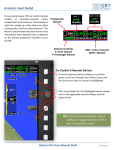
1
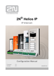
PRINTER’S INSTRUCTIONS:
MANUAL,OWNERS,WHI-4CUPG,ENGLISH - LINEAR P/N: 220720 A - INK: BLACK - MATERIAL: 60 LB. WHITE COATED WITH 80 LB. WHITE COATED COVER - SIZE: 8.500” X 5.500” - SCALE: 1-1 - FOLDING: ALBUM-FOLD - BINDING: SADDLE-STITCH
VOICE-ACTIVATED
INTERCOM SYSTEM
Owner’s Manual
For Wireless Intercom
Model WHI-4CUPG
220720 A IMAGE 1
EXPLANATION OF GRAPHIC WARNING SYMBOLS
This symbol is intended to alert the user to the
presence of un-insulated “dangerous voltage” within
the product’s enclosure that may be of sufficient
magnitude to constitute a risk of electric shock.
This symbol is intended to alert the user to
the presence of important operating and
maintenance (Servicing) instructions in the
literature accompanying the device.
CAUTION
RISK OF ELECTRIC SHOCK
DO NOT OPEN
CAUTION: TO REDUCE THE RISK OF ELECTRIC SHOCK
DO NOT REMOVE COVER (OR BACK)
NO USER-SERVICEABLE PARTS INSIDE
REFER SERVICE TO QUALIFIED PERSONNEL
✶ WARNING! To prevent fire or shock hazard,
do not expose this device to rain, water, or
wet locations.
✶ WARNING! Do not insert any metallic object
through ventilation grilles.
✶ CAUTION! Prevent electric shock, match
wide blade of plug to wide slot, fully insert.
IMPORTANT SAFETY NOTES
☞ POWER SOURCE This unit should only be connected to a 110-120 VAC power
source as marked on the unit.
☞ GROUNDING OR POLARIZATION This unit is equipped with a polarized AC
power cord plug (a plug having one blade wider than the other). This plug will fit
into the power outlet only one way. This is a safety feature. If you are unable to
insert the plug fully into the outlet, try reversing the plug. If the plug still fails to
fit, contact your electrician to have a suitable outlet installed. Do not defeat the
safety purpose of the polarized plug.
☞ NON USE PERIODS Always turn the unit off and unplug when it is not being
used or left unattended for long periods of time.
☞ OBJECT AND LIQUID ENTRY Never push objects of any kind into the unit
through the cabinet slots as they may touch dangerous voltage points or short
out parts that could result in a fire or electric shock. Never spill liquid of any kind
on the unit.
☞ CLEANING Unplug the unit from the wall outlet before cleaning or polishing it.
Do not use liquid cleaners, aerosol cleaners, gasoline or other flammable fluid.
Clean the exterior of the unit with a slightly damp cloth.
☞ WATER AND MOISTURE Do not use power line operated units near water
- for example, near a bathtub, washbowl, kitchen sink, or laundry tub, in a wet
basement, or near a swimming pool.
☞ VENTILATION The appliance should be situated so that its location or position
does not interfere with its proper ventilation. For example, the unit should not be
situated on a bed, sofa, rug or placed in a built-in installation that may block the
flow of air through the ventilation openings.
220720 A IMAGE 2
☞ POWER CORD PROTECTION Power supply cords should be routed so that
they are not likely to be walked on or pinched by items placed upon or against
them paying particular attention to cords at plugs, convenience receptacles, and
the point where they exit from the appliance.
☞ READ INSTRUCTIONS All the safety and operating instructions should be read
before the product is operated.
☞ RETAIN INSTRUCTIONS The safety and operating instructions should be
retained for future reference.
☞ HEED WARNINGS All warnings on the product and in the operating instructions
should be adhered to.
☞ FOLLOW INSTRUCTIONS All operating and use instructions should be
followed.
☞ ATTACHMENTS Do not use attachments not recommended by the product
manufacturer as they may cause hazards.
☞ ACCESSORIES Do not place this product on an unstable cart, stand, tripod,
bracket, or table. The product may fall, causing serious injury to a child or adult,
and serious damage to the product. Use only with a cart, stand, tripod, bracket or
table recommended by the manufacturer, or sold with the product. Any mounting
of the product should follow the manufacturer’s instructions, and should use a
mounting accessory recommended by the manufacturer.
☞ OVERLOADING Do not overload wall outlets, extension cords, or integral
convenience receptacles as this can result in a risk of fire or electric shock.
☞ REPLACEMENT PARTS When replacement parts are required, be sure the
service technician has used replacement parts specified by the manufacturer
or have the same characteristics as the original part. Unauthorized substitutions
may result in fire, electric shock, or other hazards.
☞ SAFETY CHECK Upon completion of any service or repairs to this product, ask
the service technician to perform safety checks to determine that the product is
in proper operating condition.
☞ WALL OR CEILING MOUNTING The product should be mounted to a wall or
ceiling only as recommended by the manufacturer.
☞ HEAT The product should be situated away from heat sources such as radiators,
heat registers, stoves, or other products (including amplifiers) that produce
heat.
1
220720 A IMAGE 3
IMPORTANT SERVICE NOTES
☞ DAMAGE REQUIRING SERVICE Unplug the unit from the wall outlet and refer
servicing to qualified service personnel under the following conditions.
➙ If liquid has been spilled into the unit.
➙ If the unit has been exposed to water.
➙ If the unit has been dropped or enclosure
damaged.
➙ If the unit does not operate normally when
following the operating instructions.
➙ When the unit exhibits a distinct change in
performance.
➙ When the power-supply cord or plug is
damaged.
THE USER SHOULD NOT ATTEMPT TO SERVICE THE
UNIT. ALL SERVICING SHOULD BE REFERRED TO
QUALIFIED PERSONNEL.
Changes or modifications to the unit may void the
users authority to operate the equipment.
2
220720 A IMAGE 4
CONTENTS
INTRODUCTION . . . . . . . . . . . . . . . . . . . . . . . . . . . . . . . . . . . . . . . . . . . 3
INTERCOM SYSTEM FEATURES . . . . . . . . . . . . . . . . . . . . . . . . . . . . . 3
INTERCOM COMPONENTS . . . . . . . . . . . . . . . . . . . . . . . . . . . . . . . . . . 4
OPERATING INSTRUCTIONS . . . . . . . . . . . . . . . . . . . . . . . . . . . . . . . . 5
SPECIFICATIONS . . . . . . . . . . . . . . . . . . . . . . . . . . . . . . . . . . . . . . . . . . 6
INTRODUCTION
Congratulations on the purchase of your new Voice-activated Intercom
System!
Please read these instructions carefully before using your system and follow
all of the directions to ensure proper operation.
This instruction manual explains in simple steps how to use and care for your
new Voice-activated Intercom System in homes, offices or businesses.
INTERCOM SYSTEM FEATURES
❐ Allows a choice of four channels to talk to or monitor an unlimited
number of rooms or offices.
❐
Excellent clarity of sound. No background hum or static.
❐
No installation or batteries required. Plug into any AC outlet and
talk.
❐
For hands-free operation or for continuous audio monitoring of a
room, press the AUTO TALK button.
❐
For larger homes or offices additional units may be added.
❐
Compatible with all Westinghouse Intercoms (except Models
WHIDBI-5C & WHI-3C900).
❐
Full one year limited warranty.
For technical assistance
Call: 1-800-842-5378
3
220720 A IMAGE 5
INTERCOM COMPONENTS
3
2
4
5
1
10
9
4
6
8
7
1.
CHANNEL BUTTONS 1-4
Allows you to select between channels. Click one button down to
select a channel. Click the button up to deselect the channel.
2.
CHANNEL INDICATORS 1-4
Indicates the selected channel.
3.
TALK INDICATOR
Lights when the intercom is activated.
4.
SPEAKER
Clearly transmits pure, static-free, two-way voice communication.
5.
POWER INDICATOR
Lights when power is on.
6.
POWER/VOLUME KNOB
Turns the unit on and off, also controls the volume.
7.
MICROPHONE
High-gain microphone monitors your voice.
8.
TALK BUTTON
Press to talk. Release to listen.
9.
CALL BUTTON
Pages other units on the selected channel.
10. AUTO TALK BUTTON
Locks down for automatic voice-activated monitoring.
220720 A IMAGE 6
OPERATING INSTRUCTIONS
1.
Plug each unit into an AC outlet.
2.
Set each intercom unit to the desired channel using one of the
four CHANNEL buttons.
3.
Turn the POWER/VOLUME knob clockwise until the intercom’s
POWER indicator lights. Set the VOLUME knob to mid-level.
4.
To call a unit, momentarily press the CALL button, this will
produce a call tone on other intercoms set to the same channel.
5.
When the receiving unit sounds, press the TALK button to talk,
release to listen. Adjust the VOLUME knob as required. For best
results, speak in a normal voice, arms length from the intercom.
6.
For hands-free operation or for continuous audio monitoring of a
room, simply press the AUTO TALK button on the intercom. When
the AUTO TALK button is locked down, the intercom will monitor
the sound in the area. When the sound level is loud enough
to trigger the voice-activation, the intercom will automatically
transmit the sound on the selected channel.
5
220720 A IMAGE 7
SPECIFICATIONS
DESCRIPTION
SPECIFICATION
POWER SOURCE
110V-120V AC
CARRIER FREQUENCY
Channel A
230 KHz
Channel B
260 KHz
Channel C
290 KHz
Channel D
200 KHz
RF OUTPUT POWER
35 mW Average into a 5-ohm load
AUDIO OUTPUT POWER
500 mW
MODULATION METHOD
Frequency Modulation (FM)
TRANSMISSION AND RECEPTION
Phase Locked Loop (P.L.L.)
DIMENSIONS
6.9” x 5.7” x 1.7”
WEIGHT
1 Lb.
Copyright © 2003 Linear Corporation
220720 A
220720 A IMAGE 8