1
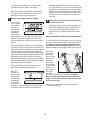
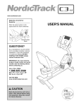
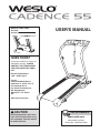
Model No. WMTL19408
Serial No.
Version No. 0
Serial Number Decal
USER'S MANUAL
QUESTIONS?
If you have questions, or if parts are
damaged or missing, PLEASE
CONTACT THE STORE WHERE
YOU PURCHASED THIS PRODUCT.
Electric Specifications:
120V ~ 60 Hz Type Y
Vendor:
Comercializadora Mexico
Americana, S. de R.L. de C.V.
Av. Nextengo No. 78
Col. Santa Cruz Acayucan
Del. Azcapotzalco
Mexico D.F., C.P. 02770
R.F.
www.iconservice.com
CAUTION
Read all precautions and instructions in this manual before using
this equipment. Save this manual
for future reference.
Visit our website at
www.weslo.com
new products, prizes,
fitness tips, and much more!
TABLE OF CONTENTS
IMPORTANT PRECAUTIONS . . . . . . . . . . . . . . . . . . . . . . . . . . . . . . . . . . . . . . . . . . . . . . . . . . . . . . . . . . . . . . . . .3
BEFORE YOU BEGIN . . . . . . . . . . . . . . . . . . . . . . . . . . . . . . . . . . . . . . . . . . . . . . . . . . . . . . . . . . . . . . . . . . . . . . .5
ASSEMBLY . . . . . . . . . . . . . . . . . . . . . . . . . . . . . . . . . . . . . . . . . . . . . . . . . . . . . . . . . . . . . . . . . . . . . . . . . . . . . . .6
OPERATION AND ADJUSTMENT . . . . . . . . . . . . . . . . . . . . . . . . . . . . . . . . . . . . . . . . . . . . . . . . . . . . . . . . . . . . .9
HOW TO FOLD AND MOVE THE TREADMILL . . . . . . . . . . . . . . . . . . . . . . . . . . . . . . . . . . . . . . . . . . . . . . . . . .12
MAINTENANCE AND TROUBLESHOOTING . . . . . . . . . . . . . . . . . . . . . . . . . . . . . . . . . . . . . . . . . . . . . . . . . . . .13
EXERCISE GUIDELINES . . . . . . . . . . . . . . . . . . . . . . . . . . . . . . . . . . . . . . . . . . . . . . . . . . . . . . . . . . . . . . . . . . .15
ORDERING REPLACEMENT PARTS . . . . . . . . . . . . . . . . . . . . . . . . . . . . . . . . . . . . . . . . . . . . . . . . . .Back Cover
Note: A PART IDENTIFICATION CHART, an EXPLODED DRAWING, and a PART LIST are located at the end of
this manual.
WESLO is a registered trademark of ICON IP, Inc.
2
IMPORTANT PRECAUTIONS
WARNING:
To reduce the risk of burns, fire, electric shock, or injury to persons, read the
following important precautions and information before operating the treadmill.
1. It is the responsibility of the owner to ensure
that all users of this treadmill are adequately
informed of all warnings and precautions.
12. Failure to use a properly functioning surge
suppressor could result in damage to the control system of the treadmill. If the control system is damaged, the walking belt may change
speed, accelerate, or stop unexpectedly,
which may result in a fall and serious injury.
2. Use the treadmill only as described.
3. Place the treadmill on a level surface, with at
least eight feet of clearance behind it and two
feet on each side. Do not place the treadmill
on any surface that blocks air openings. To
protect the floor or carpet from damage, place
a mat under the treadmill.
13. Keep the power cord and the surge suppressor away from heated surfaces.
14. Never move the walking belt while the power
is turned off. Do not operate the treadmill if
the power cord or plug is damaged, or if the
treadmill is not working properly. (See MAINTENANCE AND TROUBLESHOOTING on page
13 if the treadmill is not working properly.)
4. Keep the treadmill indoors, away from moisture and dust. Do not put the treadmill in a
garage or covered patio, or near water.
5. Do not operate the treadmill where aerosol
products are used or where oxygen is being
administered.
15. Read, understand, and test the emergency
stop procedure before using the treadmill (see
STEP-BY-STEP CONSOLE OPERATION on
page 10).
6. Keep children under the age of 12 and pets
away from the treadmill at all times.
16. Never start the treadmill while you are standing on the walking belt. Always hold the
handrails while using the treadmill.
7. The treadmill should not be used by persons
weighing more than 250 pounds.
17. The treadmill is capable of high speeds.
Adjust the speed in small increments to avoid
sudden jumps in speed.
8. Never allow more than one person on the
treadmill at a time.
9. Wear appropriate exercise clothes when
using the treadmill. Do not wear loose clothes
that could become caught in the treadmill.
Athletic support clothes are recommended for
both men and women. Always wear athletic
shoes; never use the treadmill with bare feet,
wearing only stockings, or in sandals.
18. Never leave the treadmill unattended while it is
running. Always remove the key and unplug
the power cord when the treadmill is not in use.
19. Do not attempt to raise, lower, or move the
treadmill until it is properly assembled. (See
ASSEMBLY on page 6 and HOW TO FOLD
AND MOVE THE TREADMILL on page 12.)
You must be able to safely lift 45 pounds (20
kg) to raise, lower, or move the treadmill.
10. When connecting the power cord (see page 9),
plug the power cord into a surge suppressor
(not included) and plug the surge suppressor
into a grounded circuit capable of carrying 15
or more amps. No other appliance should be on
the same circuit. Do not use an extension cord.
20. When folding or moving the treadmill, make
sure that the storage latch is fully closed.
21. Do not change the incline of the treadmill by
placing objects under the treadmill.
11. Use only a single-outlet surge suppressor that
meets all of the specifications described on
page 9. To purchase a surge suppressor,
please see your local electronics store.
3
22. Inspect and properly tighten all parts of the
treadmill regularly.
scribed in this manual. Never remove the
motor hood unless instructed to do so by an
authorized service representative. Servicing
other than the procedures in this manual
should be performed by an authorized service
representative only.
23. Never drop or insert any object into any
opening.
24.
DANGER: Always unplug the power
25. This treadmill is intended for in-home use
only. Do not use this treadmill in any commercial, rental, or institutional setting.
cord immediately after use, before cleaning
the treadmill, and before performing the maintenance and adjustment procedures de-
WARNING:
Before beginning this or any exercise program, consult your physician. This
is especially important for persons over the age of 35 or persons with pre-existing health problems.
Read all instructions before using. ICON assumes no responsibility for personal injury or property
damage sustained by or through the use of this product.
SAVE THESE INSTRUCTIONS
The decals shown here have been placed on the treadmill. If a decal is missing, or if it is not legible, please
go to www.iconservice.com and order a free replacement decal. Apply the decal in the location shown.
Note: The decals are not shown at actual size.
!
!
4
HOW TO FOLD AND MOVE THE TREADMILL
HOW TO FOLD THE TREADMILL FOR STORAGE
Unplug the power cord. CAUTION: You must be able to
safely lift 45 pounds (20 kg) to raise, lower, or move the
treadmill.
1
1. Hold the metal frame firmly in the location shown by
the arrow at the right. CAUTION: To decrease the possibility of injury, do not lift the frame by the plastic
foot rails. Make sure to bend your legs and keep your
back straight. As you raise the frame, make sure to lift
with your legs rather than your back. Raise the frame
about halfway to the vertical position.
2. Move your right hand to the position shown and hold the
treadmill firmly. Using your left hand, pull the latch knob
to the left and hold it. Raise the frame until the catch is
past the latch pin. Slowly release the latch knob; make
sure that the latch pin is resting securely against the
catch.
Frame
2
To protect the floor or carpet from damage, place a
mat under the treadmill. Keep the treadmill out of direct sunlight. Do not leave the treadmill in the storage position in temperatures above 85° Fahrenheit.
Latch
Pin
Knob
Catch
HOW TO MOVE THE TREADMILL
Before moving the treadmill, convert the treadmill to the storage position as described above. make sure that the latch
pin is resting securely against the catch.
1. Hold the handrails and place one foot against a wheel.
2. Tilt the treadmill back until it rolls freely on the wheels.
Carefully move the treadmill to the desired location. Never
move the treadmill without tipping it back. To reduce
the risk of injury, use extreme caution while moving
the treadmill. Do not attempt to move the treadmill
over an uneven surface.
3. Place one foot against a wheel, and carefully lower the
treadmill until it is in the storage position.
Handrail
Wheel
HOW TO LOWER THE TREADMILL FOR USE
1. See drawing 2 above. Hold the treadmill with your right hand as shown. Pull the latch knob to the left and hold
it. Pivot the frame down until it is past the latch pin.
2. See drawing 1 above. Hold the metal frame firmly with both hands, and lower it to the floor. CAUTION: To
decrease the possibility of injury, do not lower the frame by gripping only the plastic foot rails. Do not
drop the frame to the floor. Make sure to bend your legs and keep your back straight.
12
ASSEMBLY
Assembly requires two persons. Set the treadmill in a cleared area and remove all packing materials; do not
dispose of the packing materials until assembly is completed. Do not remove the long wire is inside the Right
Handrail until told to. Note: The underside of the treadmill walking belt is coated with high-performance lubricant.
During shipping, a small amount of lubricant may be transferred to the top of the walking belt or the shipping carton. This does not affect treadmill performance. If there is lubricant on top of the walking belt, simply wipe off the
lubricant with a soft cloth and a mild, non-abrasive cleaner.
Assembly requires the included hex key
wrench
, and wire cutters
.
and your own Phillips screwdriver
, adjustable
Note: To identify small parts used during assembly, see the PART IDENTIFICATION CHART in the center of
this manual. Some parts may be preassembled. To avoid damaging plastic parts, do not use power tools
for assembly.
1. Attach the six Base Pads (19) to the bottom of the Base
(71) with six Base Pad Screws (42). Note: The Base
Pads may be preassembled.
1
71
42
19
!
42
19
!
2. Have a second person hold the Base (71) in the position
shown.
Identify the Right Handrail (6) which has a large hole near
the lower end.
Hold the Right Handrail (6) so that the bend is in the
position shown. Insert two Handrail Bolts (12) into the
bracket on the Right Handrail. Attach the Right Handrail
to the Base (71) with the Handrail Bolts, two Handrail
Washers (30) and two Nuts (17). Do not tighten the
Nuts yet.
Attach the Left Handrail (7) to the Base (71) in the same
way.
6
2
12
19
42
19
42
19
30
17
Large
Hole
7
6
Bend
42
12
30
17
30
71
3. With the help of a second person, raise the Handrails
(6, 7) so the Base (71) is flat on the floor as shown.
Attach the Wheels (15) to the outer sides of the Base
(71) with two Wheel Bolts (14) and two Wheel Nuts (88)
as shown. Do not overtighten the Wheel Nuts; the
Wheels should turn freely.
3
55
Position the front of the treadmill Frame (55) between the
Handrails (6, 7) as shown. Next, locate the long wire inside of the lower end of the Right Handrail (see the inset
drawing). Tie the end of the wire securely to the end of
the Wire Harness (22). Then, pull the opposite end of the
wire until the end of the Wire Harness is extending from
the upper end of the Right Handrail.
4. Have a second person lift and hold the front end of the
Frame (55). Hold a Frame Spacer (13) between the Right
Handrail (6) and the Frame. Attach the Right Handrail to
the Frame with a Frame Bolt (10), a Handrail Washer
(30), and a Handrail Star Washer (60).
6
7
22
71
22
4
13
5
60
1
6
30
10
Connector
22
Plastic
Ties
22
7
14
6
55
Untie the wire from the end of the Wire Harness (22).
Insert the end of the Wire Harness through the three
looped plastic ties. Next, press the end of the Wire
Harness into the connector on the back of the Console
(1) in the location shown. The end of the Wire Harness
should slide easily into the connector and snap into
place. If it does not, turn the end of the Wire Harness and
then insert it. IF THE CONNECTORS ARE NOT CONNECTED PROPERLY, THE CONSOLE MAY BE DAMAGED WHEN THE POWER IS TURNED ON.
15
6
Wire
Repeat this step on the left side of the treadmill.
5. Hold the Console (1) near the Right Handrail (6). Touch
the Right Handrail to discharge any static.
88
6. Set the Console (1) on the Right Handrail (6) and the Left
Handrail (not shown). Finger tighten four Console Screws
(70) (only two are shown) into the Console. After you
have started all four Console Screws, tighten them.
6
1
22
Insert the excess Wire Harness (22) down into the Right
Handrail (6). Tighten the three plastic ties around the Wire
Harness, and then cut off the ends of the plastic ties.
6
70
7. Attach the Console Back (4) to the Console (1) with four
16mm Screws (58). Note that there is a slot in the side of
the Console Back for the wire—make sure that no wires
are pinched.
7
Plastic
Ties
1
58
58
4
Slot
8. Carefully lower the Handrails (6, 7) to the floor. Center the
Frame (55) between the Handrails, and tighten the four
Handrail Bolts (12). Then, raise the Handrails to the vertical position.
See drawing 8a. Attach the Storage Latch Assembly (41)
to the Left Handrail (7) with two 16mm Screws (58).
Make sure that the Storage Latch Assembly is oriented as shown.
See HOW TO CHANGE THE INCLINE OF THE TREADMILL on page 11. Adjust the incline legs and insert
the incline pins into the incline legs.
9. Make sure that all parts are properly tightened before
you use the treadmill. Keep the included hex key in a
secure place. The hex key is used to adjust the walking
belt (see page 14). To protect the floor or carpet, place a
mat under the treadmill.
8
58
8
55
8a
7
12
6, 7
58
41
DIAGRAM OF THE CONSOLE
Note: If there is a sheet of clear plastic
on the console, remove the plastic.
Clip
Key
CAUTION: Before operating the
console, read the following precautions.
• Do not stand on the walking belt when turning on the power.
• Always wear the clip (see the drawing
above) while operating the treadmill.
• Adjust the speed in small increments to
avoid sudden jumps in speed.
• To reduce the possibility of electric shock,
keep the console dry. Avoid spilling liquids
on the console and place only sealed water
bottles in the water bottle holders.
Next, stand on the foot rails of the treadmill. Find the
clip attached to the key (see the drawing above), and
slide the clip securely onto the waistband of your
clothes. Then, insert the key fully into the console.
After a moment, the display will light. Important: In an
emergency situation, the key can be pulled from
the console, causing the walking belt to slow to a
stop. Test the clip by carefully taking a few steps
backward; if the key is not pulled from the console,
adjust the position of the clip.
Follow the steps below to operate the console.
1
2
STEP-BY-STEP CONSOLE OPERATION
Before operating the console, make sure that the
power cord is properly
plugged in (see page 9).
Reset
Next, locate the reset/off circuit breaker on the treadmill
frame near the power cord.
Make sure that the circuit breaker is in the reset position.
10
Insert the key fully into the console.
A moment after the key is inserted, the display will
light.
Press the Digital Speed increase button to start
the walking belt.
A moment after the button is pressed, the walking
belt will begin to move at 1 mph. Hold the handrails
and begin walking. As you exercise, change the
speed of the walking belt as desired by pressing
the Digital Speed buttons. Each time a button is
pressed, the speed setting will change by 0.1
mph; if a button is held down, the speed setting
will change in increments of 0.5 mph.
OPERATION AND ADJUSTMENT
THE PRE-LUBRICATED WALKING BELT
and plug the surge suppressor into an appropriate
outlet that is properly installed and grounded in
accordance with all local codes and ordinances.
Important: The treadmill is not compatible with
GFCI-equipped outlets.
Your treadmill features a walking belt coated with highperformance lubricant. IMPORTANT: Never apply silicone spray or other substances to the walking
belt or the walking platform. Such substances will
deteriorate the walking belt and cause excessive
wear.
This product is for use on a nominal 120-volt circuit,
and has a grounding plug that looks like the plug illustrated in drawing 1 below. A temporary adapter that
looks like the adapter illustrated in drawing 2 may be
used to connect the surge suppressor to a 2-pole
receptacle as shown in drawing 2 if a properly
grounded outlet is not available.
HOW TO PLUG IN THE POWER CORD
DANGER: Improper connection
of the equipment-grounding conductor can
result in an increased risk of electric shock.
Check with a qualified electrician or serviceman if you are in doubt as to whether the
product is properly grounded. Do not modify
the plug provided with the product—if it will
not fit the outlet, have a proper outlet
installed by a qualified electrician.
1
Surge Suppressor
Grounding Pin
Grounding Pin
Your treadmill, like any other type of sophisticated
electronic equipment, can be seriously damaged by
sudden voltage changes in your homeʼs power.
Voltage surges, spikes, and noise interference can
result from weather conditions or from other appliances
being turned on or off. To decrease the possibility of
your treadmill being damaged, always use a surge
suppressor with your treadmill (see drawing 1 at
the right). To purchase a surge suppressor, please
see your locel electronics store.
2
Use only a single-outlet surge suppressor that is
UL 1449 listed as a transient voltage surge suppressor (TVSS). The surge suppressor must have a
UL suppressed voltage rating of 400 volts or less
and a minimum surge dissipation of 450 joules.
The surge suppressor must be electrically rated for
120 volts AC and 15 amps. There must be a monitoring light on the surge suppressor to indicate
whether it is functioning properly. Failure to use a
properly functioning surge suppressor could result
in damage to the control system of the treadmill. If
the control system is damaged, the walking belt
may change speed, accelerate or stop unexpectedly, which may result in a fall and serious injury.
This product must be grounded. If it should malfunction or break down, grounding provides a path of least
resistance for electric current to reduce the risk of electric shock. This product is equipped with a cord having
an equipment-grounding conductor and a grounding
plug. Plug the power cord into a surge suppressor,
Grounded Outlet Box
Grounded Outlet
Grounding Plug
Grounded Outlet Box
Adapter
Surge Suppressor
Lug
Metal Screw
The temporary adapter should be used only until a
properly grounded outlet (drawing 1) can be installed
by a qualified electrician.
The green-colored rigid ear, lug, or the like extending
from the adapter must be connected to a permanent
ground such as a properly grounded outlet box cover.
Whenever the adapter is used it must be held in place
by a metal screw. Some 2-pole receptacle outlet box
covers are not grounded. Contact a qualified electrician to determine if the outlet box cover is
grounded before using an adapter.
9
To stop the walking belt, press the Stop button.
The time will begin to flash in the display.
3
Note: The first time the treadmill is used, observe
the alignment of the walking belt, and center the
walking belt if necessary (see page 14).
Monitor your progress with the display.
4
As you exercise, the lower
left corner of
the display
can show the
elapsed time
and the distance that you
have walked or run. The lower right corner of the
display can show the speed of the walking belt
and the approximate number of calories you have
burned.
hold down the Stop button for a few seconds. An
“E” for English miles or an “M” for metric kilometers
will appear in the priority display. Press the Digital
Speed increase button to change the unit of measurement if desired. When the desired unit of measurement is selected, remove the key and then
reinsert it.
When you are finished exercising, remove the
key from the console.
Step onto the foot rails, press the Stop button, and
remove the key from the console. Put the key in a
secure place. Then, switch the reset/off circuit
breaker to the “off” position and unplug the power
cord.
HOW TO CHANGE THE INCLINE OF THE TREADMILL
To vary the intensity of your exercise, you can change
the incline of the treadmill. There are three incline levels. Before changing the incline, remove the key
from the console and unplug the power cord. Next,
fold the treadmill to the storage position (see page 12).
The upper half of the display is the priority display.
The priority display can show the elapsed time, the
distance that you have walked or run, the speed of
the walking belt, or the approximate number of
calories you have burned. Press the Display button
repeatedly until the priority display shows the information that you are most interested in viewing.
Note: While information is shown in the priority display, the information will not be shown in the lower
left or right corner of the display.
To change
the incline,
first remove
the incline pin
Incline
from one of
Pin
the incline
Incline
legs. Adjust
Leg
the incline leg
to the desired
height, and
Incline
fully reinsert
Pin
the incline
pin. Adjust
the other incline leg in the same way. CAUTION:
Make sure that both incline legs are at the same
height and that both incline pins are fully inserted
into the incline legs.
To reset the display, press the Stop button, remove the key, and then reinsert the key.
Note: The
console can
display speed
and distance
in either miles
or kilometers.
To see which
unit of measurement is selected, hold down the Stop button,
insert the key into the console, and continue to
After you have adjusted the incline legs, lower the
treadmill (see page 12).
11
BEFORE YOU BEGIN
Thank you for selecting the WESLO® CADENCE 55
treadmill. The CADENCE 55 treadmill combines advanced technology with innovative design to let you
enjoy an excellent form of cardiovascular exercise in
the convenience and privacy of your home. And when
youʼre not exercising, the unique CADENCE 55 treadmill can be folded up, requiring less than half the floor
space of other treadmills.
ing this manual, please see the front cover of this manual. To help us assist you, note the product model
number and serial number before contacting us. The
model number of the treadmill is WMTL19408.0. The
serial number can be found on a decal attached to the
treadmill (see the front cover of this manual for the location).
Before reading further, please review the drawing
below and familiarize yourself with the labeled parts.
For your benefit, read this manual carefully before
using the treadmill. If you have questions after readWater Bottle Holder
(Bottle not included)
Console
Handrail
Key/Clip
Storage Latch
Hood
Reset/Off
Circuit Breaker
Walking Belt
Foot Rail
Wheel
Incline Leg
Rear Roller
Adjustment Bolts
5
MAINTENANCE AND TROUBLESHOOTING
Most treadmill problems can be solved by following the steps below. Find the symptom that applies, and
follow the steps listed. If further assistance is needed, please see the front cover of this manual.
PROBLEM: The power does not turn on
SOLUTION: a. Make sure that the power cord is plugged into a surge suppressor, and that the surge suppressor
is plugged into a properly grounded outlet (see page 9). Use only a single-outlet surge suppressor
that meets all of the specifications described on page 9. Important: The treadmill is not compatible
with GFCI-equipped outlets.
b. After the power cord has been plugged in, make sure that the key is fully inserted into the console.
c. Check the reset/off circuit breaker located on the
treadmill frame near the power cord. If the switch
protrudes as shown, the circuit breaker has tripped.
To reset the circuit breaker, wait for five minutes,
and then press the switch back in.
PROBLEM: The power turns off during use
c
Reset
Tripped
SOLUTION: a. Check the reset/off circuit breaker (see the drawing above). If the circuit breaker has tripped, wait
for five minutes and then press the switch back in.
b. Make sure that the power cord is plugged in.
c. Remove the key from the console. Reinsert the key fully into the console.
d. If the treadmill still will not run, please see the front cover of this manual.
PROBLEM: The displays of the console do not function properly
SOLUTION: a. Remove the key from the console and UNPLUG THE
POWER CORD. Remove the five indicated Hood
Screws (8) and two Foot Rail Screws (52). Then, remove the Hood (23).
Locate the Reed Switch (46) and the Magnet (49) on
the left side of the Pulley (53). Turn the Pulley until the
Magnet is aligned with the Reed Switch. Make sure
that the gap between the Magnet and the Reed
Switch is about 1/8". If necessary, loosen the indicated
Screw (5), move the Reed Switch slightly, and then
retighten the Screw. Reattach the Hood (not shown),
and run the treadmill for a few minutes to check for a
correct speed reading.
13
a
23
52
8
52
1/8"
5
46
Top View
8
8
8
49
53
PROBLEM: The walking belt slows when walked on
SOLUTION: a. Use only a single-outlet surge suppressor that meets all of the specifications described on page 9.
b. If the walking belt is overtightened, treadmill performance may decrease and the walking belt may become damaged. Remove the key and UNPLUG THE
POWER CORD. Using the hex key, turn both rear
roller bolts counterclockwise, 1/4 of a turn. When the
walking belt is properly tightened, you should be able
to lift each edge of the walking belt 2 to 3 inches off
the walking platform. Be careful to keep the walking
belt centered. Then, plug in the power cord, insert the
key, and run the treadmill for a few minutes. Repeat
until the walking belt is properly tightened.
b
2"–3"
Rear Roller
Bolts
c. If the walking belt still slows when walked on, please see the front cover of this manual.
PROBLEM: The walking belt is off-center or slips when walked on
SOLUTION: a. If the walking belt has shifted to the left, first remove the key and UNPLUG THE POWER CORD.
Using the hex key, turn the left rear roller bolt clockwise 1/2 of a turn. Be careful not to overtighten the
walking belt. If the walking belt has shifted to the
right, turn the left rear roller bolt counterclockwise 1/2
of a turn. Then, plug in the power cord, insert the key,
and run the treadmill for a few minutes. Repeat until
the walking belt is centered.
b. If the walking belt slips when walked on, first remove
the key and UNPLUG THE POWER CORD. Using
the hex key, turn both rear roller bolts clockwise, 1/4
of a turn. When the walking belt is correctly tightened,
you should be able to lift each edge of the walking
belt 2 to 3 inches off the walking platform. Be careful
to keep the walking belt centered. Then, plug in the
power cord, insert the key, and carefully walk on the
treadmill for a few minutes. Repeat until the walking
belt is properly tightened.
14
a
b
EXERCISE GUIDELINES
WARNING:
is activity that requires large amounts of oxygen for
prolonged periods of time. This increases the demand
on the heart to pump blood to the muscles, and on the
lungs to oxygenate the blood. For aerobic exercise,
adjust the speed and incline of the treadmill until your
heart rate is near the highest number in your training
zone.
Before beginning
this or any exercise program, consult your
physician. This is especially important for individuals over the age of 35 or individuals
with pre-existing health problems.
HOW TO MEASURE YOUR HEART RATE
The following guidelines will help you to plan your exercise program. For more detailed exercise information, obtain a reputable book or consult your physician.
To measure your
heart rate, stop exercising and place two
fingers on your wrist
as shown. Take a sixsecond heartbeat
count, and then multiply the result by ten to
find your heart rate. (A six-second count is used because your heart rate will begin to slow when you stop
exercising.)
EXERCISE INTENSITY
Whether your goal is to burn fat or to strengthen your
cardiovascular system, the key to achieving the desired
results is to exercise with the proper intensity. The
proper intensity level can be found by using your heart
rate as a guide. The chart below shows recommended
heart rates for fat burning and aerobic exercise.
WORKOUT GUIDELINES
Each workout should include three important parts:
A Warm-up—Warming up prepares the body for exercise by increasing circulation, delivering more oxygen
to the muscles, and raising the body temperature.
Begin each workout with 5 to 10 minutes of stretching
and light exercise to warm up.
To find the proper heart rate for you, first find your age
at the top of the chart (ages are rounded off to the
nearest ten years). Next, find the three numbers below
your age. The three numbers are your “training zone.”
The lower two numbers are recommended heart rates
for fat burning; the highest number is the recommended heart rate for aerobic exercise.
Training Zone Exercise—After warming up, increase
the intensity of your exercise until your heart rate is in
your training zone for 20 to 60 minutes. (During the
first few weeks of your exercise program, do not keep
your heart rate in your training zone for longer than 20
minutes.) Breathe regularly and deeply as you exercise—never hold your breath.
Fat Burning
A Cool-down—Finish each workout with 5 to 10 minutes of stretching to cool down. This will increase the
flexibility of your muscles and will help to prevent postexercise problems.
To burn fat effectively, you must exercise at a relatively
low intensity level for a sustained period of time. During
the first few minutes of exercise, your body uses easily
accessible carbohydrate calories for energy. Only after
the first few minutes does your body begin to use
stored fat calories for energy. If your goal is to burn fat,
adjust the speed and incline of the treadmill until your
heart rate is near one of the lower two numbers in your
training zone.
EXERCISE FREQUENCY
To maintain or improve your condition, complete three
workouts each week, with at least one day of rest between workouts. After a few months, you may complete up to five workouts each week if desired. The key
to success is to make exercise a regular and enjoyable
part of your everyday life.
Aerobic Exercise
If your goal is to strengthen your cardiovascular system, your exercise must be “aerobic.” Aerobic exercise
15
PART IDENTIFICATION CHART
Remove this chart and use it to identify small parts during assembly. Save this chart and the EXPLODED
DRAWING/PART LIST for future reference.
Handrail Washer (30)–6
16mm Screw
(58)–6
Handrail Star
Washer (60)–2
Console Screw
(70)–4
Nut (17)–4
Wheel Nut
(88)–2
Base Pad
Screw (42)–6
Handrail Bolt (12)–4
Wheel Bolt (14)–2
Frame Bolt (10)–2
PART LIST—Model No. WMTL19408.0
Key No.
1
2
3
4
5
6
7
8
9
10
11
12
13
14
15
16
17
18
19
20
21
22
23
24
25
26
27
28
29
30
31
32
33
34
35
36
37
38
39
40
41
42
43
44
45
46
47
48
Qty.
1
4
1
1
6
1
1
5
2
2
2
4
2
2
2
1
4
1
6
13
1
1
1
1
1
4
2
1
1
6
2
1
1
1
1
1
1
2
1
2
1
6
1
1
3
1
2
1
Description
Console
Round Endcap
Key/Clip
Console Back
Electronics Screw
Right Handrail
Left Handrail
Hood Screw
Motor Tension Bolt
Frame Bolt
Rear Roller Bracket Screw
Handrail Bolt
Frame Spacer
Wheel Bolt
Wheel
Right Rear Roller Bracket
Nut
Belly Pan Grommet
Base Pad
13mm Screw
Latch Warning Decal
Wire Harness
Hood
Left Rear Roller Bracket
Belly Pan
Belt Guide Screw
Belt Guide
6mm Allen Wrench
4mm Allen Wrench
Handrail Washer
Platform Bolt, Front
Controller Bracket
Front Roller Star Washer
Front Roller Adj. Bolt
Controller
Motor Bolt
Left Foot Rail
Motor Tension Nut
Motor Star Washer
Outlet Plate Screw
Storage Latch Assembly
Base Pad Screw
Drive Motor Assembly
Power Cord Assembly
Hood Clip
Reed Switch
Platform Bolt, Rear
Reed Switch Clip
Key No.
Qty.
Description
R0908A
49
1
Magnet
50
1
Motor Belt
2
Roller Adj. Bolt
51
52
10
Foot Rail Screw
53
1
Front Roller/Pulley
54
1
Right Foot Rail
55
1
Frame
56
1
Walking Belt
57
1
Walking Platform
58
6
16mm Screw
59
2
Motor Bolt
60
2
Handrail Star Washer
61
3
8" Cable Tie
62
1
Dust Guard
63
2
Incline Leg
64
2
Incline Pin
65
1
Voltage Warning Decal
66
2
Rear Roller Star Washer
67
2
Frame Endcap
68
2
U-nut
69
4
Bracket Star Washer
70
4
Console Screw
71
1
Base
72
1
Rear Roller
73
2
Outlet Plate Washer
74
2
Outlet Plate Nut
75
2
Nut
76
1
Ferrite Clamp
77
4
Isolator
78
1
Catch
79
1
Motor Bracket
80
1
Choke
81
5
Plastic Tie
82
1
Grommet
83
2
Choke Screw
84
5
18 mm Screw
85
1
Power Cord Ground Screw
86
1
Releasable Tie
87
1
Reset/Off Circuit Breaker
88
2
Wheel Nut
89
1
Motor Nut
90
2
Latch Catch Screw
#
1
4" White Wire, Male/Female
#
1
4" Black Wire, 2F
#
1
4" Blue Wire, 2F
#
1
Userʼs Manual
Specifications are subject to change without notice.
#These parts are not illustrated.
51
67
64
63
75
11
5
69
24
66
47
52
21
51
37
29
67
75
20
28
16
52
5
69
72
78
66
90
52
77
63
11
47
26
27
52
57
52
20
31
64
54
77
52
52
49
48
55
56
46
89
53
68
50
20
20
77
31
43
59
61
86
26
33
38
36
79
39
27
68
52
34
83
9
77
20
80
38
20
8
84
62
35
20
25
5
32
69
8
45
74
5
20
74
8
8
85
18
87
23
7
20
40
73
45
3
8
73
44
45
76
40
19
42
19
42
60
30
30
10
41
58 58
4
17
15
13
6
70
2
71
19
42
42
19
88
14
58
12
2
22
58
30
22
82
13
19
60
1
17
81
81
42
65
88
30
20
70
2
19
42
10
84
2
15
14
12
84
EXPLODED DRAWING—Model No. WMTL19408.0
R0908A
ORDERING REPLACEMENT PARTS
To order replacement parts, please see the front cover of this manual. To help us assist you, be prepared to give
the following information:
• the MODEL NUMBER of the product (WMTL19408.0)
• the NAME of the product (WESLO CADENCE 55 treadmill)
• the SERIAL NUMBER of the product (see the front cover of this manual)
• the KEY NUMBER and DESCRIPTION of the desired part(s) (see the PART LIST and the EXPLODED
DRAWING in the center of this manual)
Part No. 274599 R0908A
Printed in China © 2008 ICON IP, Inc.