1
CP9190
Elite AutoScanner ®Pro
Section 1 – Using This Manual
This manual contains instructions for the use and setup of your Scan Tool. A
table of contents and glossary are provided to make this manual easy to use.
Some of the information shown in text or illustrations is obtained using optional
equipment. A Sales Representative can determine option availability.
This section contains a list of conventions used.
1
Safety Messages
Refer to Safety Precautions on page Safety - i.
Check Note
A check note provides additional information about the subject in the preceding
paragraph.
Example:
✓
English is the default measurement unit.
Equipment Tips and Lists
Equipment tips and lists provide information that applies to specific equipment.
Each tip is introduced by this icon ❒ for easy identification.
Example:
❒ Observe all vehicle and/or equipment manufacturer’s cautions and
warnings when testing with the Scan Tool.
Equipment Damage
Situations arise during testing that could damage the vehicle or the test
equipment. The word IMPORTANT signals these situations.
Example:
IMPORTANT
Failure to follow these instructions could damage the Scan Tool.
••••••••••••••••••••••••••••••••••••••••••••••••••••••••• 1–1
Using This Manual
Functions and Selections
Diagnostic and tool functions performed by the Scan Tool are highlighted in
bold.
Example:
The View Data function allows you to view the vehicle’s parameter identification
(PID) data in real time.
1
Menus
The menus on the Scan Tool display are referenced in the procedures and are
highlighted in bold-italic text.
Example:
When the OBDII Function List menu displays, the Scan Tool is ready for use.
Questions and Responses
Messages and user responses are CAPITALIZED.
Example:
The Scan Tool displays the pending DTCs or a message stating SYSTEM
PASS: NO FAULT DETECTED.
Manual References
Used to reference other sections of the manual.
Example:
For more information on DTCs, refer to “OBD II Diagnostic Trouble Codes
(DTCs)” on page 2-15
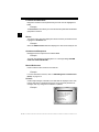
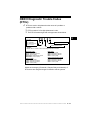
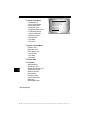
Screens
Certain help messages, information, and data that are displayed on the scan
tool are also shown in graphical text boxes. The screens are presented as
examples and may change as the software is updated.
Example:
Main Menu
Global OBD II
Domestic Vehicles
European Vehicles
Asian Vehicles
Review Data
Print Data
System Setup
1–2 ••••••••••••••••••••••••••••••••••••••••••••••••••••••••
Section 2 – Getting Started
Introduction
The Scan Tool was developed by experts in the automotive service
industry to help diagnose vehicles and assist in troubleshooting
procedures.
The Scan Tool monitors vehicle events and retrieves codes from the
vehicle’s control modules to help pinpoint problem areas.
All information, illustrations and specifications contained in this manual
are based on the latest information available from industry sources at
the time of publication.
No warranty (expressed or implied) can be made for its accuracy or
completeness, nor is any responsibility assumed by the manufacturer
or anyone connected with it for loss or damages suffered through
reliance on any information contained in this manual or misuse of
accompanying product. The manufacturer reserves the right to make
changes at any time to this manual or accompanying product without
obligation to notify any person or organization of such changes.
••••••••••••••••••••••••••••••••••••••••••••••••••••••••• 2–1
2
Getting Started
Using the CD
✓
✓
✓
2
✓
The included CD is NOT required to operate the Scan Tool
Install the CD application prior to connecting the Scan Tool to the
PC.
Some of the items included on the CD are:
❒
❒
❒
❒
❒
❒
Manuals included with Scan Tool
DTC lookup software
Scan Tool update software
Adobe Acrobat Reader Installer
Print Capture
Other product information
To be able to use the included CD the PC must meet the following
minimum requirements:
❒
❒
❒
❒
❒
❒
❒
486 PC
4 MB of RAM
Microsoft Windows 98 SE, ME, 2000, and XP
CD ROM Drive
Adobe Acrobat Reader
Internet Explorer 4.0 or newer
Screen Resolution of 800 x 600
– If screen resolution is 800 x 600, in Display Properties, Settings
Tab, set Font Size to Small Fonts.
2–2 ••••••••••••••••••••••••••••••••••••••••••••••••••••••••
Getting Started
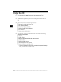
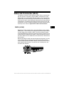
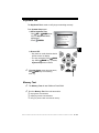
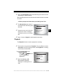
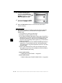
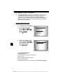
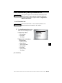
Installing Applications On Included CD
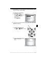
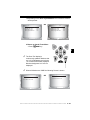
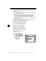
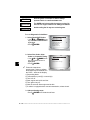
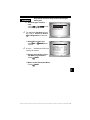
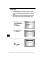
1. Close all programs on the computer.
2. Place the CD in CD-Drive.
✓
If CD does not start automatically;
❒ Select the Start button.
❒ Select Run...
❒ Enter “X:\Setup.htm” in Open Box on
Computer and select OK.
Run
Start
❒ “X” is the CD-ROM drive
letter on the computer.
Enter
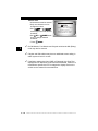
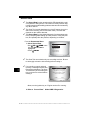
3. Follow screen prompts on the computer to install the
applications.
••••••••••••••••••••••••••••••••••••••••••••••••••••••••• 2–3
2
Getting Started
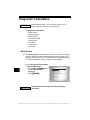
Introduction to On-Board Diagnostics
OBD I
The original on-board diagnostics (OBD I) lacked consistency in
communication and interface while allowing different interpretations
among vehicle manufacturers. Ford and Chrysler used different types
of engine control computers and data link connectors ( DLCs), and GM
varied the trouble codes and communication protocols from
year-to-year.
2
OBD II
On-board diagnostics version II (OBD II) is a system that the Society of
Automotive Engineers (SAE) developed to standardize automotive
electronic diagnosis.
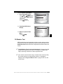
Beginning in 1996, most new vehicles sold in the United States were
fully OBD II compliant.
✓
Technicians can now use the same tool to test any OBD II
compliant vehicle without special adapters. SAE established
guidelines that provide:
❒ A universal connector, called the DLC, with dedicated pin
assignments.
❒ A standard location for the DLC, visible under the dash on driver’s
side.
❒ A standard list of diagnostic trouble codes (DTCs) used by all
manufacturers.
❒ A standard list of parameter identification (PID) data used by all
manufacturers.
❒ Ability for vehicle systems to record operating conditions when a
fault occurs.
❒ Expanded diagnostic capabilities that records a code whenever a
condition occurs that affects vehicle emissions.
❒ Ability to clear stored codes from the vehicle’s memory with a
Scan Tool.
2–4 ••••••••••••••••••••••••••••••••••••••••••••••••••••••••
Getting Started
SAE Publications
SAE has published hundreds of pages of text defining a standard
communication protocol that establishes hardware, software, and
circuit parameters of OBD II systems. Unfortunately, vehicle
manufacturers have different interpretations of this standard
communications protocol. As a result, the generic OBD II
communications scheme varies, depending on the vehicle. SAE
publishes recommendations, not laws, but the Environmental
Protection Agency (EPA) and California Air Resources Board (CARB)
made many of SAE’s recommendations legal requirements that vehicle
manufacturers were required to phase in over a three-year period.
Beginning in 1994, vehicles with a new engine management computer
( about 10% of each manufacturers fleet ) were supposed to comply
with OBD II standards. For 1995, OBD II systems were to appear on
about 40% of the new vehicles sold in the United States. Some of the
1994-1995 OBD II systems were not fully compliant, so the Government
granted waivers to give manufacturers time to fine-tune their systems.
Beginning in 1996, most of the new vehicles sold in the United States
were fully OBD II compliant.
The tables below highlight changes for GM, Ford, and Chrysler. If this
seems confusing, don’t worry. The Scan Tool makes it easy. Based on
the vehicle identification (VIN) information selected during Scan Tool
setup, the vehicle is automatically recognized. All you have to do is
choose the correct adapter cable and jumper wires (if necessary).
Details on adapter cables and jumper wires may be found in Data LInk
Connector on page 2-9
.
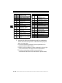
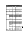
GM On-Board Diagnostics
System
OBD I Control Module
OBD II Control Module
Years
Description
Most vehicles used the 12-pin ALDL (Assembly Line Data Link)
located under the dash on the driver side. Some 94-95 vehicles
1981–1995 used the 16-pin OBD II (J1962) data link connector (DLC), but
use the Historical application software. Refer to the vehicle’s
Vehicle Emission Control Information label.
1994*-Present Complies with OBD II regulations and uses the J1962 DLC.
* OBD II system is used on certain 1994-1995 vehicles equipped with a 2.2L, 2.3L, 3.8L, 4.3L or 5.7L
engines.
••••••••••••••••••••••••••••••••••••••••••••••••••••••••• 2–5
2
Getting Started
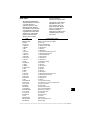
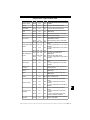
Ford On-Board Diagnostics
System
Long Name
MCU
Microprocessor Control Unit
EEC-IV
MECS
EEC-V
2
PTEC
Years
Electronic Engine Control,
Fourth generation
Mazda Electronic Control
System
Electronic Engine Control,
Fifth generation
Powertrain Electronic
Controller
Description
Used in police vehicles, containing carbureted
1980 –1991
engines. Uses the MCU DLC.
Most Ford vehicles equipped with North
1984 –1995
American engines. Uses the EEC-IV DLC.
Vehicles equipped with Mazda-sourced engines.
1988 –1995
Uses MECS 6-pin and 17-pin DLCs.
Complies with OBD II regulations and uses the
1994* – present
OBD II J1962 DLC.
Complies with OBD II regulations and uses the
2000 – present
OBD II J1962 DLC.
* EEC-V OBD II system used in 1994-1995 vehicles equipped with a 3.8L or 4.6L engine.
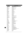
Chrysler On-Board Diagnostics
System
Long Name
Years
Description
SMEC
Single Module Engine
1989–1990
Controller
Used a 6-pin Serial Communication Interface (SCI)
DLC and has bidirectional capability.
SBEC
Single Board Engine
Controller
1989*–1995
Used two types of DLCs: a 6-pin SCI and a 6-pin LH
series.
The first to allow a tool to reset the EMR light on trucks.
OBD II
PCM
OBD II Powertrain
Control Module
1995**– present
Complies with OBD II regulations and uses the OBD II
J1962 DLC.
JTEC
Jeep/Truck Engine
Controller
1996– present
Complies with OBD II regulations and uses the OBD II
J1962 DLC.
The JTEC system is used on light-duty trucks and
Jeeps
* In 1989, the SBEC system was installed in selected vehicles with 3.0L V6 engines.
** Some vehicles in 1995 were equipped with the OBD II PCM.
2–6 ••••••••••••••••••••••••••••••••••••••••••••••••••••••••
Getting Started
Data Link Connector (DLC)
The data link connector (DLC) allows the Scan Tool to communicate
with the vehicle’s computer(s). Before OBD II, manufacturers used
different DLC’s to communicate with the vehicle. use the proper DLC
adapter cable to connect the Scan Tool to the vehicle. Also, the vehicle’s
DLC may be found in several different places and have many different
configurations. The following describes the DLCs used by Ford, GM
and Chrysler. The DLC location and types for domestic vehicles can be
looked up in the charts in Appendix B - Data Link Connectors.
OBD II (J1962)
Beginning in 1996, vehicles sold in the United States use the J1962
(OBD II) DLC, a term taken from a physical and electrical specification
number assigned by the SAE (J1962). The DLC should be located
under the dashboard on the driver’s side of the vehicle. If the DLC is not
located under the dashboard as stated, a decal describing its location
should be attached to the dashboard in the area the DLC should have
been located.
Because the OBD II J1962 connector has power and ground, you only
need a single cable connection to the tool for both power and tool
communications. Attach the OBD II adapter cable to the extender cable,
(both supplied with the tool) to connect the tool. Certain pins in the
connector are reserved.
.
••••••••••••••••••••••••••••••••••••••••••••••••••••••••• 2–7
2
Getting Started
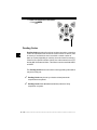
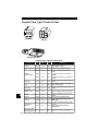
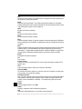
Data Link Connector (DLC) Pins
2
1 - Manufacturer Reserved
2 - J1850 Bus+
3 - Manufacturer Reserved
4 - Chassis Ground
5 - Signal Ground
6 - CAN High, J-2284
7 - K Line, ISO 9141-2 & ISO/DIS 14230-4
8 - Manufacturer Reserved
9 - Manufacturer Reserved
10 - J1850 Bus11 - Manufacturer Reserved
12 - Manufacturer Reserved
1
8
9
16
13 - Manufacturer Reserved
14 - CAN Low, J-2284
15 - L Line, ISO 9141-2 & ISO/DIS 14230-4
16 - Battery Power
Ford Historic
Ford used three types of DLCs with their OBD I systems. Refer to
Appendix B - Data Link Connectors for the adapter cable needed for
your vehicle.
IMPORTANT Use the cigarette lighter cable to provide power to the
Scan Tool for all systems.
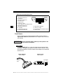
EEC-IV/MCU
The EEC-IV/MCU DLC is a large six-sided connector with a pigtail
connector. The pigtail connector is not used on MCU vehicles – leave
the pigtail unattached. The EEC-IV/MCU cable adapter is included with
the Scan Tool.
Cable Adapter
Vehicle DLC
EEC-IV/MCU
EEC-IV/MCU
To Scan
Tool
STI Pigtail
EEC-IV only
2–8 •••••••••••••••••••••••••••••••••••••••••••••••••••••••
Getting Started
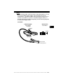
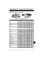
MECS
MECS vehicles (1988 –1995) use either a 6-pin (with pigtail) or a 17-pin
DLC. Use the MECS 6-pin adapter cable kit (CP9131) for both
configurations. The MECS adapter cable kit includes jumper wires to
connect to the MECS 17-pin DLC. The MECS adapter cable kit is
optional and must be purchased separately. Use the following diagrams
to connect the adapter cable.
6-Pin MECS
Cable Adapter
Vehicle DLC
6-Pin MECS
6-Pin MECS
P/N CP9131
2
To Scan
Tool
Pigtail
6
4 5
1 2 3
STI Pigtail
Clip to good
vehicle ground
•••••••••••••••••••••••••••••••••••••••••••••••••••••••• 2–9
Getting Started
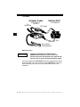
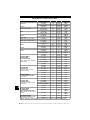
17-Pin MECS
Adapter Cable
Vehicle DLC
6-Pin MECS
17-Pin MECS
To
Scan Tool
P/N CP9131
STI Pigtail
2
4
1
5
2
6
3
STO
Clip to good
vehicle ground
MECS Ford Probe
IMPORTANT
Certain Ford Probes have a WHITE TACH
CONNECTOR located very close to the 6-pin
self-test connector and bundled in the same wiring
harness. This is not the self-test input (STI) pigtail.
Connect the pigtail to the BLACK STI connector located farther back on
the wire harness. If the tool is connected to the WHITE tach connector,
serious damage may result and may void warranty. Refer to the
illustration.
2 – 10 • • • • • • • • • • • • • • • • • • • • • • • • • • • • • • • • • • • • • • • • • • • • • • • • • • • • • • •
Getting Started
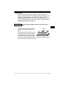
GM Historic
Prior to1996, most GM vehicles used the 12-pin Assembly Line
Diagnostic Link (ALDL) DLC. The GM ALDL cable kit includes the ALDL
adapter and cigarette lighter power cable. This adapter cable is
included with the Scan Tool. In 1994 and 1995, certain GM vehicles
used the J1962 (OBD II) DLC, but are not OBD II compliant. Refer to
Appendix B - Data Link Connectors.
IMPORTANT Use the cigarette lighter cable to provide 12V to the
tool.
2
The ALDL DLCs are usually located
under the dashboard on the driver’s
side.
ALDL
On Corvettes and Fieros, the DLC may
F E D C B A
be located in the center console behind
G H J K L M
the ashtray. Refer to service manual
for exact location. It may be in full view,
or it may be recessed behind a panel. An opening in the panel should
allow access to the recessed connector.
• • • • • • • • • • • • • • • • • • • • • • • • • • • • • • • • • • • • • • • • • • • • • • • • • • • • • • • • 2 – 11
Getting Started
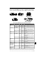
Chrysler Historic
Prior to 1996, most Chrysler vehicles used either the serial
communications interface (SCI) or LH DLC. Refer to Appendix B Data Link Connectors for DLC type and location. The SCI adapter
cable is included with the Scan Tool. The LH adapter cable (CP9130)
can be purchased from your dealer.
IMPORTANT Use the cigarette lighter cable to provide 12V to the tool
when using the SCI adapter cable.
2
Serial Communications Interface SCI
The SCI (serial communications interface) DLC
is a 6-pin connector located in the engine
compartment. The adapter cable to be used on
these vehicles is supplied with the tool. This
cable is labeled CHRY on the 15-pin DB style
connector and SCI on the vehicle end.
LH
This DLC is used on LH platform vehicles. The
LH style DLC is a small, blue, rectangular 6-pin
connector located in the passenger
compartment below the dashboard to the right of
the steering column.
SCI
LH (P/N CP9130)
The LH Adapter Cable (CP9130) is optional and
must be purchased separately.
2 – 12 • • • • • • • • • • • • • • • • • • • • • • • • • • • • • • • • • • • • • • • • • • • • • • • • • • • • • • •
Getting Started
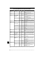
OBD II Diagnostic Trouble Codes
(DTCs)
✓
DTCs are used to help determine the cause of a problem or
problems with a vehicle.
❒ DTCs consist of a five-digit alphanumeric code.
❒ The DTCs format and general code types are shown below.
.
Bx - Body
Cx - Chassis
Px - Powertrain
Ux - Network Comm.
x = 0, 1, 2 or 3
2
P0 1 0 1
Specific Fault Designation
Vehicle Specific System
Example:
P0101 - Mass or Volume Air Flow Circuit Range/Performance Problem
Powertrain Codes
P0xxx - Generic (SAE)
P1xxx - Manufacturer Specific
P2xxx - Generic (SAE)
P30xx-P33xx - Manufacturer Specific
P34xx-P39xx - Generic (SAE)
Chassis Codes
C0xxx - Generic (SAE)
C1xxx - Manufacturer Specific
C2xxx - Manufacturer Specific
C3xxx - Generic (SAE)
Body Codes
B0xxx - Generic (SAE)
B1xxx - Manufacturer Specific
B2xxx - Manufacturer Specific
B3xxx - Generic (SAE)
Network Communication Codes
U0xxx - Generic (SAE)
U1xxx - Manufacturer Specific
U2xxx - Manufacturer Specific
U3xxx - Generic (SAE)
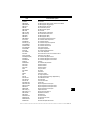
Within each category (Powertrain, Chassis, Body and Network) of
DTCs there are assigned ranges for different vehicle systems.
• • • • • • • • • • • • • • • • • • • • • • • • • • • • • • • • • • • • • • • • • • • • • • • • • • • • • • • • 2 – 13
Getting Started
2
Lower Upper
Assigned DTC System
P0000 P00FF Fuel Air Metering Auxiliary
Emission Controls
P0100 P02FF Fuel Air Metering
P0300 P03FF Ignition System or Misfire
P0400 P04FF Auxiliary Emission Controls
P0500 P05FF Vehicle Speed Idle Control
Auxiliary Inputs
Computer and Auxiliary
P0600 P06FF
Outputs
P0700 P09FF Transmission
P0A00 P0AFF Hybrid Propulsion
Manufacturer Control Fuel &
P1000 P10FF Air Metering, Auxiliary
Emission Controls
Manufacturer
Control Fuel &
P1100 P12FF
Air Metering
Manufacturer Control Ignition
P1300 P13FF
System or Misfire
Manufacturer Control
P1400 P14FF Auxiliary emission Controls
Manufacturer Cntrl Veh.Spd.
P1500 P15FF Idle Speed Control Auxiliary
Inputs
✓
Lower
Upper
P1600 P16FF
P1700 P19FF
P2000 P22FF
P2300 P23FF
P2400 P24FF
P2500 P25FF
P2600 P26FF
P2700 P27FF
P2900 P32FF
P3300
P3400
U0000
U0100
U0300
U0400
P33FF
P34FF
U00FF
U02FF
U03FF
U04FF
Assigned DTC System
Manufacturer Control
Auxiliary Inputs Auxiliary
Outputs
Manufacturer Control
Transmission
Fuel Air Metering Auxiliary
emission Controls
Ignition System or Misfire
Auxiliary Emission Controls
Auxiliary Inputs
Computer and Auxiliary
Outputs
Transmission
Fuel Air Metering Auxiliary
Emission Controls
Ignition System
Cylinder Deactivation
Network Electrical
Network Communication
Network Software
Network Data
J2012 and ISO 15031-6 are standards for all DTCs, established by
the SAE, International Organization for Standardization (ISO) and
other governing bodies.
❒ Codes and definitions assigned by these specifications are
known as Generic OBD II codes.
❒ OBD II requires compliance to these standards for all cars, light
trucks, APVs, MPVs, and SUVs sold in the United States.
❒ Codes not reserved by the SAE are reserved for the
manufacturer and referred to as Manufacturer Specific Codes.
2 – 14 • • • • • • • • • • • • • • • • • • • • • • • • • • • • • • • • • • • • • • • • • • • • • • • • • • • • • • •
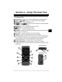
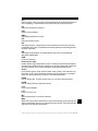
Section 3 – Using The Scan Tool
The Scan Tool
1 LCD Display – backlit, 128 x 64 pixel display with contrast adjustment.
UP and
DOWN arrow keys – moves selection UP or DOWN.
2
3
ENTER key – selects displayed items.
4
LEFT and
RIGHT arrow keys – selects YES or NO, and selects data
5
6
7
8
9
10
11
12
13
parameters for custom data list.
BACK key – goes to the previous screen or level.
ON/OFF key – turns power ON or OFF.
HELP key – accesses the Help Function.
USER key - allows the operator to access a feature from the Diagnostic
Menu with a touch of a key.
DLC Cable – provides connection for vehicle interface.
USB Port – provides a USB connection for the computer.
12V Power Jack– provides power to the Scan Tool when reprogramming
from a personal computer, communicating with Ford, GM and Chrysler
Historic vehicles, or off-vehicle reviewing of codes and printing.
Serial Number Plate – provides serial number of Scan Tool.
Battery Compartment – provides power to the Scan Tool when
reprogramming from a personal computer or off-vehicle reviewing of codes
and printing.
Top of Scan Tool
1
10
2
9
11
Back of Scan Tool
7
3
12
4
4
8
13
5
6
2
••••••••••••••••••••••••••••••••••••••••••••••••••••••••• 3–1
3
Using The Scan Tool
Specifications
Display: Backlit, 128 x 64 pixel display with contrast adjust
Operating Temperature: 0 to 50°C (32 to 122°F)
Storage Temperature: -20 to 70°C (-4 to 158°F)
Internal Power: 9V Battery
External Power: 7 to 16 Volts
✓
3
A minimum of 8.0 V is required for most control modules to operate
properly in a vehicle.
Power Dissipation: 5 Watts maximum.
Dimensions:
Height
1.25"
31.75 mm
Width
3.875"
98.4 mm
Length
9.125"
231.8 mm
3–2 ••••••••••••••••••••••••••••••••••••••••••••••••••••••••
Using The Scan Tool
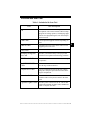
Included with Scan Tool
Table 1: Included with Scan Tool
Part
Part Description
CD
The CD contains the Manual in English, French
and Spanish. The CD also includes a DTC lookup
program for looking up DTCs, and language applications for reprogramming the Scan Tool in Spanish and French.
USB Cable
Used to print and upgrade software depending on
tool.
OBD II Cable
Communicate between the vehicle and tool. Also
supplies power to the tool.
Carry Case
Place to store the Scan Tool when tool is not in use.
Warranty & Registration Card
Provides you with the ability to keep up to date
with the newest updates and technology available.
GM Historic Cable
Used to communicate with all GM vehicles using a
12-pin DLC.
Ford EEC-IV/MCU
Cable
Used to communicate with all Ford vehicles that
use the large 6-sided connector.
Chrysler SCI Cable
Used to communicate with all Chrysler vehicles
using the L-shaped 6-pin connector located in the
engine compartment.
Extension Cable
Used to attach the GM Historic cable, Ford EECIV/MCU cable or Chrysler SCI cable to the Scan
Tool.
Cigarette Lighter Cable
Provides power to the Scan Tool for vehicles that
require the Ford EEC-IV/MCU cable, GM Historic
cable or Chrysler SCI cable.
••••••••••••••••••••••••••••••••••••••••••••••••••••••••• 3–3
3
Using The Scan Tool
✓
Replacement Parts are available from the manufacturer by
contacting customer service.
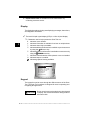
Display
The display has a large viewing area displaying messages, instructions,
and diagnostic information.
✓
The back-lit liquid crystal display (LCD) is a 128 x 64 pixel display.
❒ Characters used to help operate the Scan Tool are:
3
`
✓
?
]
[
Indicates cursor location.
Indicates information is available for an item or multiple items.
Indicates when Help is available.
Indicates additional information is available on previous screen
by using the
UP arrow key.
Indicates additional information is available on next screen by
DOWN arrow key.
using the
Indicates internal batteries need replaced or are not installed.
Indicates beeper is enabled.
Indicates graphical viewing available.
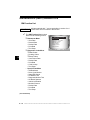
Main Menu
Global OBD II
Domestic Vehicles
European Vehicles
Asian Vehicles
Review Data
Print Data
System Setup
?
Keypad
The keypad is used to move through the different menus of the Scan
Tool. The Scan Tool’s software is designed for ease in operating and
navigating through menus.
! CAUTION
Do not use solvents such as alcohol to clean keypad
or display. Use a mild nonabrasive detergent and a
soft cotton cloth.
3–4 ••••••••••••••••••••••••••••••••••••••••••••••••••••••••
Using The Scan Tool
! CAUTION
Do not soak keypad as water might find its way
inside the Scan Tool.
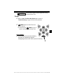
Power
✓
✓
Refer to Scan Tool Does Not Power Up in section 9
Troubleshooting on page 9-2 if there are problems.
ON/OFF button on Scan Tool turns
tool on and off.
❒ Press and hold
ON/OFF key for at
least 1 second to turn on Scan Tool.
3
Internal Battery
✓
When powered from the internal battery,
the Scan Tool disables the display’s
backlighting and turns OFF after a period of inactivity.
••••••••••••••••••••••••••••••••••••••••••••••••••••••••• 3–5
Using The Scan Tool
✓
Each time the Scan Tool is
powered up, voltage of the internal
battery is checked.
❒ If voltage is low, the Low
Battery Symbol ( ) displays
on screen.
❒ Replace the battery using
instructions provided in Battery
Replacement.
3
! CAUTION
Main Menu
Global OBD II
Domestic Vehicles
European Vehicles
Asian Vehicles
Review Data
Print Data
System Setup
If the Scan Tool will not be used for an extended
period of time, remove the battery to prevent battery
leakage from damaging the battery compartment.
Vehicle Power
When using the OBD II Cable, the power to
the Scan Tool comes from the vehicle DLC.
Diagnostic
Connector
Some vehicle cigarette lighters are not
powered when the ignition is in the OFF
position. Therefore, you may wish to use
battery clip adapters.
3–6 ••••••••••••••••••••••••••••••••••••••••••••••••••••••••
Using The Scan Tool
AC Power Adapter
An AC power adapter (not included) can be used to power the Scan Tool
when reprogramming from a personal computer or for off-vehicle
reviewing of codes and printing.12V AC-DC converters are available at
most PC and electronic stores.
✓
The Scan Tool is equipped to accept any
110 VAC - 12 VDC wall adapter with the
following specifications:
❒
❒
❒
❒
GND
12 V
500 mA minimum current unregulated wall power adapter
5.5 mm outside diameter
2.5 mm inside diameter
The inside tip is positive (+)
Scan Tool Power UP
1. Connect Power Source
• Internal Battery (9V Battery), or vehicle Power DLC
• AC Adapter, or cigarette lighter cable.
ON/OFF key
2. Press and Hold
• For 1 second until the Scan Tool turns on.
System Setup
✓
System Setup allows:
❒
❒
❒
❒
❒
❒
❒
❒
Measurement units to be changed.
Display contrast to be changed.
Auto-Power off time to be changed.
Scan Tool information to be viewed.
Display to be checked.
Operation of the keypad to be checked.
Memory of the tool to be checked.
Scan Tool to be upgraded, or programmed for a different
language.
••••••••••••••••••••••••••••••••••••••••••••••••••••••••• 3–7
3
Using The Scan Tool
✓
System Setup settings remain until internal battery becomes
discharged or is removed.
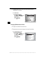
From Main Menu:
1.Select System Setup.
•Use UP or
DOWN arrow
key until System Setup is
highlighted.
ENTER.
•Press
Main Menu
Global OBD II
Domestic Vehicles
European Vehicles
Asian Vehicles
Review Data
Print Data
System Setup
?
3
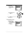
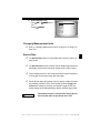
Changing Measurement Units
✓
English is the default measurement unit.
✓
Measurement units can be changed in View and Record Data.
From System Setup screen:
1.Select English/Metric.
•Use UP or
DOWN arrow
key until English/Metric is
highlighted.
ENTER.
•Press
System Setup
English/Metric
Contrast Adjust
Be eper
Auto Power Off
Tool Information
Display Test
Keyboard Test
3–8 ••••••••••••••••••••••••••••••••••••••••••••••••••••••••
Using The Scan Tool
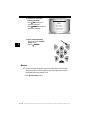
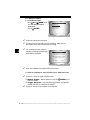
2.Select Desired
Measurement Unit.
DOWN arrow
•Use UP or
key until desired unit is
highlighted.
Measurement Units
(Default)
English/Metric
English
Metric
3.Save Measurement Setting.
•Press
ENTER.
✓
3
Press
ENTER again to return to the
System Setup menu.
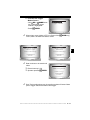
Changing Display Contrast
From System Setup screen:
1.Select Contrast Adjust.
•Use UP or
DOWN arrow
key until Display Contrast is
highlighted.
ENTER.
•Press
System Setup
English/Metric
Adjust
Display Contrast
Contrast
Be eper
Auto Power Off
Tool Information
Display Test
Keyboard Test
••••••••••••••••••••••••••••••••••••••••••••••••••••••••• 3–9
Using The Scan Tool
2.Increase or Decrease
Display Contrast.
UP arrow key to
•Use
increase Contrast.
DOWN arrow key to
•Use
decrease Contrast.
Adjust Contrast
50%
Darken
Lighten
Press ENTER
when done.
3.Save Contrast Setting
and return to the System
Setup menu.
ENTER.
•Press
3
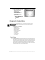
Beeper
✓
Beeper selection allows the user to turn off the Scan Tool’s beeper.
The bell symbol will not appear in the lower right hand corner of
the display when the beeper is off.
From System Setup menu:
3 – 10 • • • • • • • • • • • • • • • • • • • • • • • • • • • • • • • • • • • • • • • • • • • • • • • • • • • • • • •
Using The Scan Tool
1.Select Beeper.
UP or
DOWN
• Use
arrow key until Beeper is
highlighted.
• Press
ENTER.
2.Select desired Beeper sound
choice.
UP or
DOWN
• Use
arrow key until desired choice
is highlighted.
System Setup
English/Metric
Contrast Adjust
Be eper
Auto Power Off
Tool Information
Display Test
Keyboard Test
?
Be eper Sound
(Default)
On
English/Me
Off
3
3.Save Beeper sound setting.
• Press
ENTER.
✓
Press
ENTER again to return to the System Setup menu.
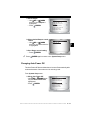
Changing Auto-Power Off
The Auto-Power Off feature allows the tool to turn off automatically after
a selected amount of time when tool is not being used.
From System Setup menu:
1.Select Auto Power Off.
•Use UP or
DOWN arrow
key until Auto Power Off is
highlighted.
ENTER.
•Press
System Setup
English/Metric
Contrast Adjust
Be eper
Auto Power Off
Tool Information
Display Test
Keyboard Test
• • • • • • • • • • • • • • • • • • • • • • • • • • • • • • • • • • • • • • • • • • • • • • • • • • • • • • • • 3 – 11
Using The Scan Tool
2.Increase or Decrease Auto
Power Off Time.
UP arrow key to
•Use
increase Time.
DOWN arrow key to
•Use
decrease Time.
Auto Power Off
15
Minutes
Increase Time
Decrease Time
Press ENTER when done.
3.Save Auto Power Off Time.
•Press
ENTER.
3
✓
Press
ENTER again to return to the
System Setup menu.
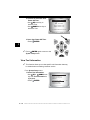
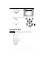
View Tool Information
✓
This function allows you to view specific tool information that may
be needed when contacting customer service.
From System Setup menu:
1.Select Tool Information.
•Use UP or
DOWN arrow
key until Tool Information is
highlighted.
ENTER.
•Press
System Setup
English/Metric
Contrast Adjust
Be eper
Auto Power Off
Tool Information
Display Test
Keyboard Test
3 – 12 • • • • • • • • • • • • • • • • • • • • • • • • • • • • • • • • • • • • • • • • • • • • • • • • • • • • • • •
Using The Scan Tool
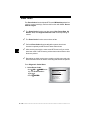
2.View Information:
❒ Serial Number (Serial No:)
❒ Software ID (SW ID:)
❒ Hardware Version
(HW Ver:)
❒ Boot Version (Boot Ver:)
❒ Product ID (Prod ID:)
❒ Board ID (Board ID:)
❒ Burn Date (Burn Date:)
❒ Burn Location (Burn Loc:)
Tool Information
Serial No:
10002076
SW ID:
0A46H
HW Ver:
1
Boot Ver:
1
Prod ID:
5
Board ID:
11
Burn Date:
04/25/04
3.Write Down Scan Tool Information.
• Space is provided on inside front cover to record the Scan Tool
information.
4.Return to Setup Tool Menu.
BACK key.
•Use the
OR
•Use the
ENTER Key.
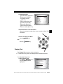
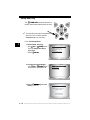
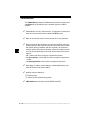
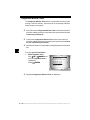
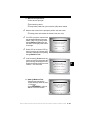
Display Test
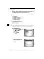
The Display Test is used to check the display.
✓
The test fills every pixel of the display with a solid black character.
From System Setup menu:
1.Select Display Test.
DOWN arrow
•Use UP or
key until Display Test is
highlighted.
System Setup
English/Metric
Contrast Adjust
Be eper
Auto Power Off
Tool Information
Display Test
Keyboard Test
• • • • • • • • • • • • • • • • • • • • • • • • • • • • • • • • • • • • • • • • • • • • • • • • • • • • • • • • 3 – 13
3
Using The Scan Tool
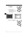
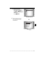
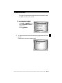
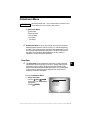
2. Start Display Test.
•Press
ENTER.
3. Look for Missing Spots.
• All characters display in solid black if
there are no concerns.
• Screen flips back and forth between
screens shown below.
3
Display Test
Press Back
to Quit
Check for missing
spots in the display
4. When Done, Press
BACK Key.
3 – 14 • • • • • • • • • • • • • • • • • • • • • • • • • • • • • • • • • • • • • • • • • • • • • • • • • • • • • • •
Using The Scan Tool
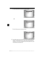
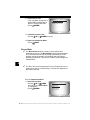
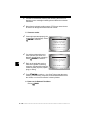
Keyboard Test
The Keyboard Test is used to verify keys are working correctly.
From System Setup menu:
1.Select Keyboard Test.
DOWN arrow
•Use UP or
key until Keyboard Test is
highlighted.
ENTER.
•Press
System Setup
English/Metric
Contrast Adjust
Be eper
Auto Power Off
Tool Information
Display Test
Keyboard
Test
test
3
2. Press a KEY.
• Key name or scroll direction should
inverse colors on display.
BACK
• The only exception is the
BACK key is pressed,
key. When
System Setup menu returns.
✓
If System Setup menu does not return,
BACK key is not working
then
correctly.
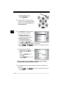
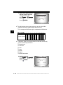
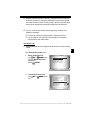
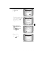
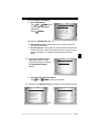
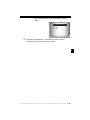
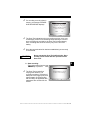
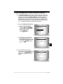
Memory Test
✓
The Memory Test will test RAM and Flash ROM.
✓
Run the Memory Test if the tool has trouble:
❒ Playing back recorded data.
❒ Displaying trouble code definitions.
❒ Doing any function that uses internal memory.
• • • • • • • • • • • • • • • • • • • • • • • • • • • • • • • • • • • • • • • • • • • • • • • • • • • • • • • • 3 – 15
Using The Scan Tool
From System Setup menu:
1.Select Memory Test.
DOWN arrow
•Use UP or
key until Memory Test is
highlighted.
ENTER.
•Press
✓
3
Dots along the bottom of the
screen show progress of the
Memory Test.
❒ Memory Test may take
System Setup
Contrast Adjust
Be eper
Auto Power Off
Tool Information
Display Test
Keyboard Test
Memory Test
Memory Test
RAM
Pass
ROM
FAIL 1234
several minutes to complete.
............
❒ Memory Test results display.
❒ If no problems were
detected, then PASS is displayed
❒ If RAM fails, an error message is shown.
❒ If ROM fails, a checksum is shown.
2. Return to System Setup menu.
•Press
ENTER.
3 – 16 • • • • • • • • • • • • • • • • • • • • • • • • • • • • • • • • • • • • • • • • • • • • • • • • • • • • • • •
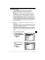
Using The Scan Tool
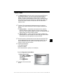
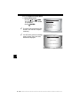
Program Mode
The Program Mode is used for
reprogramming the Scan Tool with
English, Spanish or French
languages. The Scan Tool is
programmed with English by
default.
System Setup
Be eper
Auto Power Off
Tool Information
Display Test
Keyboard Test
Memory Test
Program Mode
The Program Mode is also used for
updating the Scan Tool. Instructions
are provided with upgrades.
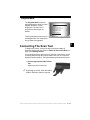
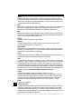
Connecting The Scan Tool
To diagnose a vehicle, connect the DLC and power adapter (if
applicable) to the Scan Tool. Refer to “Data Link Connector (DLC)” on
page 2-9 of Getting Started.
If you just want to power up the tool to do self-tests, code lookup, review
or printing data from the last vehicle tested, then you do not need to
attach the cable to the DLC. The internal battery provides power for this.
1.Connect appropriate cable to Scan
Tool
•Make sure pins are not bent.
✓
Depending on vehicle, either the OBD II
Cable or Extension Cable is required.
• • • • • • • • • • • • • • • • • • • • • • • • • • • • • • • • • • • • • • • • • • • • • • • • • • • • • • • • 3 – 17
3
Using The Scan Tool
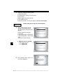
2.Find DLC on vehicle.
•For OBD II vehicles, look
under the dashboard on the
driver’s side of the vehicle.
•If the DLC is not located
under the dashboard, a
label should be there telling
the location.
For GM, Ford, and Chrysler Historic vehicles refer to “Appendix B - Data
Link Connectors".
3.Remove DLC cover if required.
3
4.Connect cable to vehicle.
•Make sure pins are not bent.
Diagnostic
Connector
✓
Use the appropriate vehicle cable for
vehicles that require the extension cable.
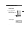
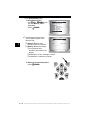
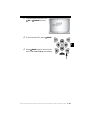
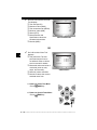
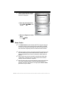
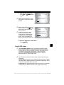
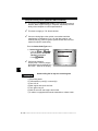
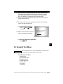
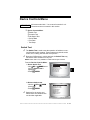
Review Data
✓
✓
The Review Data function allows the user to view the information
from the previous vehicle tested.
Scan Tool does not require power from the vehicle to use the
Review Data function.
1. Select Review Data.
DOWN arrow
•Use UP or
key until Review Data is
highlighted.
ENTER.
•Press
Main Menu
Global OBD II
Domestic Vehicles
European Vehicles
Asian Vehicles
Review Data
Print Data
System Setup
3 – 18 • • • • • • • • • • • • • • • • • • • • • • • • • • • • • • • • • • • • • • • • • • • • • • • • • • • • • • •
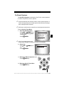
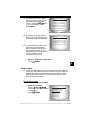
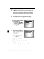
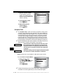
Using The Scan Tool
✓
Scan Tool Review Data function has different types of data to review
depending on vehicle selected.
Refer to appropriate section of this manual for what functions have data
for review.
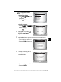
2.Follow prompts and instructions provided by Scan Tool.
✓
✓
✓
The Review Data menu shows a
checkmark next to the item(s) that
has data.
If data does not exist for function
selected to review, a message
informs the user to run a function
first.
Review Data
Readiness
Read Codes
Pending Codes
Fre eze Data
O2 Monitor Test
Diag Mon Test
Playback
I/M
Only 1 function, Playback, needs detailed instructions.
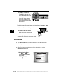
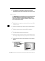
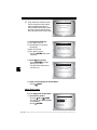
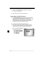
Playback
The Playback function is used to playback a recording.
✓
This function is very similar to View Data. The only difference is that
View Data is real time viewing of PIDs, while Playback is a viewing
of previously recorded PIDs.
From the Review Data menu:
1.Select Playback.
DOWN arrow
•Use UP or
key until Playback is
highlighted.
✓
Scan Tool displays a NO
RECORDING PRESENT
message if recording does not
exist.
Review Data
Fre eze Frame
State OBD Check
O2 Monitor Test
Diag Mon Tests
Playback
Vehicle Info
Modules Present
• • • • • • • • • • • • • • • • • • • • • • • • • • • • • • • • • • • • • • • • • • • • • • • • • • • • • • • • 3 – 19
3
Using The Scan Tool
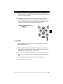
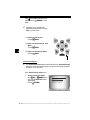
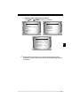
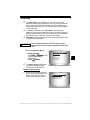
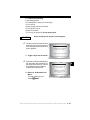
2. Play Back Recording.
•Press
ENTER.
✓
✓
The Playback has frame number
and timestamp (in seconds).
❒ Negative frames and
MIL STATUS
ABS TPS(%)
ENGINE (RPM)
A/F RATIO
CALC LOAD
ON
100
688
14:1
83.1
timestamps indicate data
recorded before trigger event.
❒ Positive frames and
FRAME:0 TM
0.0
timestamps indicate data
recorded after trigger event.
❒ Use UP or
DOWN arrow
keys to view recorded PID data of each frame.
LEFT or
RIGHT arrow keys to scroll back and forth
❒ Use
through frames.
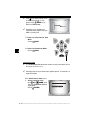
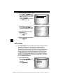
❒ If graphing is available for
selected PID, the “ ”, icon is
located on the side of the
screen.
– Press
ENTER to view
graph.
– Press
ENTER again to return
to Playback.
59%
ABS TPS (%)
100+
0 +
FRAME:0 TM
3
On GM Historic and Ford Historic
vehicles, you must select the data to
playback as an Entire Data List or
Custom Data List.
0.0
Note: Graphing is only available on 1996 and newer vehicles
equipped with an OBD II (J1962) connector.
✓
The triangle below the graph indicates the position of the frame in
the graph.
LEFT or
through graph.
❒ Use
RIGHT arrow keys to scroll back and forth
3 – 20 • • • • • • • • • • • • • • • • • • • • • • • • • • • • • • • • • • • • • • • • • • • • • • • • • • • • • • •
Using The Scan Tool
✓
✓
Different vehicles communicate at different speeds and support a
different number of PIDs. Therefore, the maximum number of frames
that can be recorded varies.
Some vehicles wait a long period of time to store a DTC after a
driveability problem occurs. If the operator selected Trigger On Codes
when making a recording, the operator might not see any drastic
change in data parameters before and after trigger point.
3.Return to Review Data menu.
BACK.
•Press
3
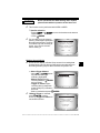
Print Data
The Print Data function allows the printing of diagnostic information
stored in the Scan Tool.
✓
✓
✓
✓
✓
Scan Tool Print Data function has different types of data to print,
depending on vehicle selected. Refer to appropriate section of this
manual for what functions have data to print.
The Scan Tool’s internal battery power can be used to print data.
Make sure you have previously installed the PC software in Using the
CD.
Launch Scanning Suite and then start printing application.
Follow all instructions on PC.
• • • • • • • • • • • • • • • • • • • • • • • • • • • • • • • • • • • • • • • • • • • • • • • • • • • • • • • • 3 – 21
Using The Scan Tool
From Special Tests menu:
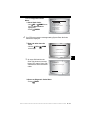
1. Select Print Data.
•Use UP or
DOWN arrow
key until Print Data is
highlighted.
ENTER.
•Press
3
✓
✓
On the Print Menu, Print All prints all data collected by the Scan Tool.
When printing playback data, Start Frame and End Frame need to be
defined.
2.Select Data To Be Printed.
•Use UP or
DOWN arrow
key.
ENTER.
•Press
✓
Special Test Menu
Diag Mon Tests
On Board Systems
Vehicle Info
Modules Present
Review Data
Print Data
The Print Menu shows a check
mark next to the item(s) that has
data.
Print Menu
Print All
I/M Readiness
Read Codes
Pending Codes
Fre eze Data
O2 Monitor Test
Diag Mon Tests
3 – 22 • • • • • • • • • • • • • • • • • • • • • • • • • • • • • • • • • • • • • • • • • • • • • • • • • • • • • • •
Using The Scan Tool
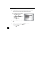
✓
When selected data does not exist in the Scan Tool’s memory, a
message informs the user to run the function.
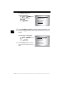
3.Return to Select Print Data screen.
•Press
ENTER.
3
Code Lookup
Code Lookup is used to look up definitions of DTCs stored in the Scan
Tool.
✓
The Scan Tool does not require power from the vehicle to perform this
function.
1. Select Code Lookup.
•Use UP or
DOWN arrow
key until Code Lookup is
highlighted.
ENTER.
•Press
Global Function List
Datastream
?
Diagnostic Codes
Special Tests
Review Data
Print Data
Code Lookup
Tool Setup
• • • • • • • • • • • • • • • • • • • • • • • • • • • • • • • • • • • • • • • • • • • • • • • • • • • • • • • • 3 – 23
Using The Scan Tool
2.Enter code.
•All characters must be entered
•Only one character can be
changed at a time.
RIGHT
•Use LEFT or
arrow keys to scroll to desired
character.
DOWN arrow
•Use UP or
keys to change selected
character.
ENTER.
• Press
3
✓
✓
✓
Code Lookup
P
P0001
Press & to
change selected digit
Press & to
select another digit
Press ENTER to view
On GM Historic, Ford Historic and Chrysler vehicles the MIL (Blinky)
code may also be entered.
Chrysler and GM vehicles may have an additional screen asking in
which system to look for a code.
If definition could not be found (SAE or Enhanced), the Scan Tool
displays No DTC Definition Found. See Service Manual. If the DTC is
manufacturer specific the DTC is assigned to display. Refer to the
vehicle service manual for exact definition.
3 – 24 • • • • • • • • • • • • • • • • • • • • • • • • • • • • • • • • • • • • • • • • • • • • • • • • • • • • • • •
Using The Scan Tool
✓
To View Previous or Next DTC use
UP or
DOWN arrow key.
P1575
Warning Buzzer
Malfunction
✓
To enter another DTC, press
BACK.
3
✓
Press
BACK again to return to menu
from which Code Lookup was selected.
• • • • • • • • • • • • • • • • • • • • • • • • • • • • • • • • • • • • • • • • • • • • • • • • • • • • • • • • 3 – 25
Using The Scan Tool
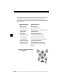
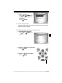
Setup User Key
The
USER KEY allows the operator to
read or erase codes with the touch of a key.
✓
The User Key can only be used when the
Scan Tool is in a vehicle specific
Function List or a sub menu.
From Tool Setup Menu:
3
1.Select Setup User Key.
DOWN arrow
•Use UP or
key until Setup User Key is
highlighted.
ENTER.
•Press
2.Choose desired setting(s).
•Use UP or
DOWN arrow
keys to move up and down list.
ENTER key to save
3.Press
settings.
Tool Setup Menu
English/Metric
Contrast Adjust
Be eper
Setup User Key
User Key Setup
Read Codes
Erase Codes
User Key Setup
User key is set to
Read Codes.
Press ENTER
to continue.
3 – 26 • • • • • • • • • • • • • • • • • • • • • • • • • • • • • • • • • • • • • • • • • • • • • • • • • • • • • • •
Using The Scan Tool
Vehicle Selection
From Main Menu:
1.Select desired vehicle to
diagnose.
•Use UP or
DOWN arrow
key to highlight.
❒ Global OBD II
❒ Domestic Vehicles
❒ European Vehicles
❒ Asian Vehicles
•Press
✓
Main Menu
Global OBD II
Domestic Vehicles
European Vehicles
Asian Vehicles
Review Data
Print Data
System Setup
ENTER.
If vehicle displayed is not the vehicle being diagnosed select
CHANGE and go to step 3.
2.Confirm selection.
RIGHT
•Use LEFT or
arrow keys.
ENTER.
•Press
Confirm Selection
2002 Corvette
S=5.7L
<KEEP>
✓
✓
CHANGE
If keeping the selected vehicle select KEEP and press
ENTER.
You will then arrive at the appropriate function list for the selected
vehicle.
If changing the selected vehicle, select CHANGE and press
ENTER, then go to step 3.
• • • • • • • • • • • • • • • • • • • • • • • • • • • • • • • • • • • • • • • • • • • • • • • • • • • • • • • • 3 – 27
3
Using The Scan Tool
3. Select erase data stored in
the tool from the previous
vehicle tested or not.
RIGHT
•Use LEFT or
arrow key.
•Press
ENTER.
✓
Select New Vehicle
Selecting a new
vehicle erases data
from previous vehicles
Continue?
<YES>
NO
On GM vehicles the tool may require you to look at the VIN to
determine the Series, Model, Engine Size and more.
❒ For example a GM Tahoe may be considered a K1500 series.
3
GM Typical VIN
VIN Position 1 2 3 4 5 6 7 8 9 10 11 12 13 14 15 16 17
Model Year
Engine Type
Chassis Type
Series
✓
Line Chassis
Description of Number
If Domestic, Asian or European Vehicles is selected, the tool may
ask for the following information:
❒
❒
❒
❒
❒
❒
❒
Manufacturer
Car/Truck
Year
Make
Model
Engine
Special Information
4.Confirm selection.
•Use LEFT or
RIGHT
arrow key.
ENTER.
•Press
Confirm Selection
2002 Corvette
S=5.7L
<KEEP>
CHANGE
3 – 28 • • • • • • • • • • • • • • • • • • • • • • • • • • • • • • • • • • • • • • • • • • • • • • • • • • • • • • •
Using The Scan Tool
✓
The following screen only displays when power comes from
vehicle.
5. Follow Instructions on the
display.
•Turn vehicle key off for 10
seconds.
•Turn vehicle key back to the on
position.
ENTER on the Scan
•Press
Tool.
Turn Key Off
Please turn the
key off for
10 seconds then
turn the key on.
Press ENTER
to continue.
3
• • • • • • • • • • • • • • • • • • • • • • • • • • • • • • • • • • • • • • • • • • • • • • • • • • • • • • • • 3 – 29
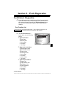
Section 4 – Global OBD II Diagnostics
✓
✓
✓
The first time the scan tool links to the vehicle, the communication
protocol is automatically detected, and is used until the Scan Tool is
turned off or another vehicle is diagnosed.
If an Error Message displays, make sure the OBDII connector is
attached, and the ignition key is on. Cycle ignition key to off for 10
seconds, then on. This may be required to reset computer. If required,
select yes to try again. If problem still exists, refer to“Error Messages”
Troubleshooting .
The Scan Tool keeps all data received from the last vehicle
selected until any of the following occurs:
❒ A new vehicle is selected.
❒ The internal 9V battery is discharged or has been removed.
❒ Scan Tool is flash programmed to update software, or to change
language.
❒ Data from last vehicle tested is erased.
✓
On initial link to vehicle, Scan Tool checks the status of I/M Monitors
no matter which function is selected.
••••••••••••••••••••••••••••••••••••••••••••••••••••••••• 4–1
4
Global OBD II Diagnostics
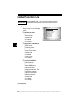
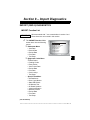
Global Function List
Items marked with “-” are covered in section 3 of this
IMPORTANT manual. These items are not covered in this section.
✓
The Global Function List is
broken down into the following
menus:
❒ Datastream Menu
❒ View Data
❒ Record Data
– Review Data
– Print Data
– Tool Setup
44
Global Function List
Datastream
Diagnostic Codes
Special Tests
Review Data
Print Data
Code Lookup
Tool Setup
❒ Diagnostic Codes Menu
❒ Read Codes
❒ Pending Codes
❒ Erase Codes
❒ View Freeze Data
–
–
–
–
Review Data
Print Data
Code Lookup
Tool Setup
❒ Special Tests Menu
❒ I/M Readiness
❒ Drive Cycle Monitor
❒ State OBD Check
❒ O2 Monitor Test
❒ Diagnostic Monitor Test
❒ On-Board Systems
❒ Vehicle Information
❒ Modules Present
– Review Data
– Print Data
– Tool Setup
(List Continued)
4 – 2• • • • • • • • • • • • • • • • • • • • • • • • • • • • • • • • • • • • • • • • • • • • • • • • • • • • • • • • •
Global OBD II Diagnostics
❒ Review Data
❒ Print Data
•I/M Readiness
•State OBD Check
•DTC (Codes)
•Pending Codes
•Freeze Frame
•O2 Monitor Test
•Diag Monitor Tests
•Playback
•Vehicle Info
•Modules Present
✓
For Global OBD II Diagnostics, The above functions have data to
review or print. For Print/Review instructions, refer to “Print Data” or
“Review Data” on page 3-21 of Using The Scan Tool.
– Code Lookup
– Tool Setup Menu
– English/Metric
– Contrast Adjust
– Beeper
– Setup User Key
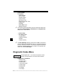
Datastream Menu
Items marked with “-” are covered in section 3 of this
IMPORTANT manual. These items are not covered in this section.
❒ Datastream Menu
❒ View Data
❒ Record Data
– Review Data
– Print Data
– Tool Setup
••••••••••••••••••••••••••••••••••••••••••••••••••••••••• 4–3
4
Global OBD II Diagnostics
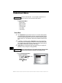
View Data
The View Data function allows real time viewing of the vehicle’s
computer module’s PID data. As the computer monitors the vehicle,
information is simultaneously transmitted to scan tool.
✓
View data allows the following items to be viewed on the scan tool:
❒
❒
❒
❒
✓
Sensor data
Operation of switches
Operation of solenoids
Operation of relays
View data can be shown as:
❒ Entire Data List
❒ Custom Data List
44
✓
Apart from Read Codes, View Data is the most useful diagnostic
function for isolating the cause of a vehicle operation problem.
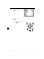
From Datastream Menu:
1. Select View Data.
•Use
UP or
DOWN arrow
key until View Data is
highlighted.
ENTER.
•Press
2. Observe while Scan Tool
validates PID MAP.
Datastream Menu
View Data
Record Data
Review Data
Print Data
Tool Setup
?
Validating PID Map
Validating PID list
PID xx of yy.
--- Please wait ---
4 – 4• • • • • • • • • • • • • • • • • • • • • • • • • • • • • • • • • • • • • • • • • • • • • • • • • • • • • • • • •
Global OBD II Diagnostics
✓
✓
Multiple PIDs may be sent if vehicle is equipped with more than one
computer module (for example a powertrain control module [PCM]
and a transmission control module [TCM]). The Scan Tool identifies
them by their identification names (ID) assigned by manufacturer
If one or more control module stops responding, the Scan Tool
displays a message.
❒ If continuing, dashes will replace data in right hand column.
❒ If no is selected, then the Scan Tool attempts to re-establish
communication with that module.
View Entire List.
✓
View Entire List shows all supported PID data for the vehicle being
tested.
4
From Select Data to View menu:
1.
2.
Select Entire Data List.
•Use UP or
DOWN arrow
key until Entire Data List is
highlighted.
ENTER.
•Press
View PIDs on Scan Tool.
DOWN arrow
•Use UP or
key.
Select Data to View
Entire Data List
Custom Data List
Customize Lines
English / Metric
A/C PRESS (psi)
A/C PRESS (V)
A/F RATIO
BARO PRESS ("Hg)
ABSLT TPS (%)
ENGINE (RPM)
CALC LOAD (%)
MAF (LB/M)
15.5
3.00
14:1
29.9
12.2
2352
83.1
0.57
••••••••••••••••••••••••••••••••••••••••••••••••••••••••• 4–5
Global OBD II Diagnostics
If the
icon displays while a PID is
ENTER to view
selected press
graph.
✓
Graphing is only available on
1996 and newer vehicles using an
OBD II (J1962) DLC.
3. Return to PID Screen.
•Press
BACK.
4. Return to Select Data to View
Menu.
BACK.
•Press
44
5. Return to Datastream Menu.
•Press
BACK.
Custom List Select
✓
The Custom Data List allows certain PIDs from the View Entire Data
List, such as those PIDs that apply to a specific driveability symptom
or system, to be selected.
From Select Data to View menu:
1.
Select Custom List Select.
•Use UP or
DOWN arrow
key until Custom Data List is
highlighted.
ENTER.
•Press
Select Data to View
Entire Data List
Custom Data List
Customize Lines
English / Metric
4 – 6• • • • • • • • • • • • • • • • • • • • • • • • • • • • • • • • • • • • • • • • • • • • • • • • • • • • • • • • •
Global OBD II Diagnostics
2. Select View Instructions or
Not.
•Use LEFT or RIGHT
arrow key.
ENTER.
•Press
Custom Setup
View instructions for
creating custom data
list?
<Yes>
3.
✓
<No>
Select PIDs to View.
•Use
UP or
DOWN
Custom Setup
MIL
($10) #3
RIGHT arrow keys to move up
($18)
MIL
($10)
and down list
TPS
($10)
TPS
($18)
• The
RIGHT arrow selects
ENGINE
($10) #1
or deselects data parameter.
ENGINE
($18) #2
CALC LOAD (%)
All selected data values are
marked with ✓ symbol.
•The LEFT arrow deselects
all marked data parameters.
• The
key starts recording data, or displaying selected data
parameters.
•The numbers to the right are the order that the PIDs were picked
and will be displayed. This feature is not available on GM and Ford
Historic vehicles.
Selected PIDs are kept until:
❒ Another vehicle is selected.
❒ You erase data stored in the Scan Tool from the previous vehicle
4.
tests.
View PIDs on Scan Tool.
•Use UP or
DOWN arrow
key.
A/C PRESS (psi)
A/C PRESS (V)
A/F RATIO
BARO PRESS ("Hg)
ABSLT TPS (%)
ENGINE (RPM)
CALC LOAD (%)
MAF (LB/M)
15.5
3.00
14:1
29.9
12.2
2352
83.1
0.57
••••••••••••••••••••••••••••••••••••••••••••••••••••••••• 4–7
4
Global OBD II Diagnostics
✓
✓
If the
icon displays while a PID
is selected press
to view
BACK key to
graph. Press
Return to PID Screen.
Graphing is only available on
1996 and newer vehicles using an
OBD II (J1962) DLC.
ABS TPS (%)
59%
100+
0
+
5. Return to Select Data to View
Menu.
•Press
BACK.
6. Return to Datastream Menu.
•Press
BACK.
44
Customize Lines
✓
✓
The Customize Lines allows the number of lines to be shown at one
time to be set from 1 to 8.
Selecting fewer lines provides faster update speeds. The default is a
eight-line display.
From Select Data to View menu:
1. Select Customize Lines.
•Use UP or
DOWN arrow
key until Customize Lines is
highlighted.
ENTER.
•Press
Select Data to View
Entire Data List
Custom Data List
Customize Lines
English / Metric
4 – 8• • • • • • • • • • • • • • • • • • • • • • • • • • • • • • • • • • • • • • • • • • • • • • • • • • • • • • • • •
Global OBD II Diagnostics
2. Select Display Lines.
DOWN arrow
•Use UP or
key.
ENTER.
•Press
Select Display Lines
1 Line
2 Lines
3 Lines
4 Lines
5 Lines
6 Lines
7 Lines
Changing Measurement Units
✓
Refer to “Changing Measurement Units” on page 3-8 of Using The
Scan Tool.
Record Data
✓
✓
✓
✓
4
The Record Data function records PIDs while vehicle is parked or
being driven.
The Record Data function is mainly used for diagnosing intermittent
driveability problems that cannot be isolated by any other method.
The recording time varies. A recording consists of frames of data prior
to the trigger and several frames after the trigger.
Some vehicles wait a long period of time to store a trouble code after
a driveability problem occurs. If the operator selected Trigger On
Codes when making a recording, the operator might not see any
drastic change in the data parameters before and after trigger point.
! CAUTION
Two people must be in vehicle when driving. One to
drive and the other to operate the Scan Tool.
••••••••••••••••••••••••••••••••••••••••••••••••••••••••• 4–9
Global OBD II Diagnostics
From Datastream Menu:
1. Select Record Data.
•Use UP or
DOWN arrow
key until Record Data is
highlighted.
ENTER.
•Press
Datastream Menu
View Data
Record Data
Review Data
Print Data
?
A
✓
✓
44
✓
Follow all instructions on display.
The ScanTool can maintain only one recording. Make sure to
thoroughly review old recording before erasing.
If a recording currently exists in
memory, a message prompting to
erase data is displayed.
Record Data
Previous recording
in memory. Do you
want to erase it and
make a new one?
<Yes>
✓
<No>
Scan Tool validates list of global PIDs from vehicle.
2. Refer to View Data to setup Custom List or View Entire List.
✓
There are 2 types of trigger methods used:
❒ Manual Trigger - allows operator to use the
✓
ENTER key to
start recording.
❒ Trigger On Codes - automatically triggers when a diagnostic
trouble code (DTC) is detected by vehicle.
Trigger on Codes is not available on all vehicles.
4 – 10 • • • • • • • • • • • • • • • • • • • • • • • • • • • • • • • • • • • • • • • • • • • • • • • • • • • • • • • •
Global OBD II Diagnostics
3. From the Pick Trigger
Method Screen.
DOWN arrow
•Use UP or
key until desired trigger
method is highlighted.
ENTER.
•Press
✓
Trigger on Codes
When trigger event (either a DTC or a Press of the
occurs, time is recorded and data is saved.
Record Data
Waiting for trouble
code to trigger
start of recording.
Press BACK
to exit.
✓
Pick Trigger Method
Manual Trigger
Data continues to be saved until
either:
❒ Record memory is full.
ENTER .
❒ Operator presses
ENTER key)
Record Data
Ready to record.
Press Enter
to start recording.
Press BACK
to exit.
Record Data
**Recording Data**
Frame xx of yy.
Press ENTER
to stop.
✓
Scan Tool recording times vary. A recording consists of frames of data
prior to trigger and several frames after trigger.
• • • • • • • • • • • • • • • • • • • • • • • • • • • • • • • • • • • • • • • • • • • • • • • • • • • • • • • • 4 – 11
4
Global OBD II Diagnostics
4. After recording, Scan Tool
displays a prompt to
Playback Data.
• Answer No to return to
Datastream Menu.
•Answer Yes to display
recorded data.
❒Refer to Playback from
Review Data and press
ENTER .
Record Data
Playback Data?
<Yes>
<No>
Diagnostic Codes Menu
Items marked with “-” are covered in section 3 of this
IMPORTANT manual. These items are not covered in this section.
44
❒ Diagnostic Codes Menu
❒ Read Codes
❒ Pending Codes
❒ Erase Codes
❒ View Freeze Data
–
–
–
–
Review Data
Print Data
Code Lookup
Tool Setup
Read Codes
✓
The Read Codes function allows the Scan Tool to read the DTCs from
the vehicle’s control modules. DTCs are used to help determine the
cause of a problem or problems with a vehicle. These codes cause the
control module to illuminate the malfunction indicator lamp (MIL)
when emission-related or driveability fault occurs. MIL is also known
as service engine soon or check engine lamp.
4 – 12 • • • • • • • • • • • • • • • • • • • • • • • • • • • • • • • • • • • • • • • • • • • • • • • • • • • • • • • •
Global OBD II Diagnostics
✓
Read Codes can be done with the key on engine off (KOEO) or with
the key on engine running (KOER).
From Diagnostic Codes Menu:
1. Select Read Codes.
•Use UP or
DOWN arrow
key until Read Codes is
highlighted.
ENTER.
•Press
✓
Diagnostic Codes Menu
Read Codes
Pending Codes
Erase Codes
View Fre eze Data
Review Data
Print Data
Code Lookup
If no DTCs are present a message stating System Pass: No Faults
Detected is displayed.
4
2. View and write down DTCs.
UP or
DOWN arrow key.
•Use
❒ In the example shown module
(MOD) is reporting the
DTCs.
P0113
1 of 3
MOD $18
IAT Sensor 1
Circuit High Input
• • • • • • • • • • • • • • • • • • • • • • • • • • • • • • • • • • • • • • • • • • • • • • • • • • • • • • • • 4 – 13
Global OBD II Diagnostics
3. Return to Diagnostic Codes Menu.
BACK.
• Press
Pending Codes
44
Pending Codes are also referred to as continuous monitor or maturing
codes. An intermittent fault causes the control module to store a code
in memory. If the fault does not occur within a certain number of
warm-up cycles (depending on vehicle), the code clears from memory.
If fault occurs a specific number of times, the code matures into a DTC
and the MIL illuminates or blinks. This function can be used with KOEO
or KOER
The Pending Codes function is used to read any pending codes which
may be currently set.
✓
✓
Pending Codes may be set by emission related powertrain
components and systems.
Pending Codes faults do not automatically indicate a faulty
component or system.
4 – 14 • • • • • • • • • • • • • • • • • • • • • • • • • • • • • • • • • • • • • • • • • • • • • • • • • • • • • • • •
Global OBD II Diagnostics
From the Diagnostic Codes Menu:
1. Select Pending Codes
•Use UP or
DOWN arrow
key until Pending Codes is
highlighted
ENTER.
•Press
✓
Diagnostic Codes Menu
Read Codes
Pending Codes
Erase Codes
View Fre eze Data
Review Data
Print Data
Code Lookup
If no Pending Codes are present a message stating System Pass:
No Faults Detected is displayed. (Do not mistake this message. It
refers only to Pending Codes and is not a warning of DTCs.)
2. If Pending Codes are Present.
•View and write down codes using
UP or
DOWN arrow key.
✓
See “Read Codes
3. Return to Diagnostic Codes Menu.
BACK.
• Press
• • • • • • • • • • • • • • • • • • • • • • • • • • • • • • • • • • • • • • • • • • • • • • • • • • • • • • • • 4 – 15
4
Global OBD II Diagnostics
Erase Codes
The Erase Codes function deletes DTCs and I/M Readiness data from
vehicle’s control module(s). Perform this function with KOEO. Do not
start the engine.
✓
✓
✓
44
✓
✓
The Erase Codes function may also erase View Freeze Data, O2
Monitor Test, and Diagnostic Monitor Test results depending on
vehicle.
The Erase Codes function sets monitors to inc.
Perform Erase Codes function only after systems have been
checked completely and DTCs have been written down.
After servicing the vehicle, erase stored DTCs and verify no codes
have been reset. If a DTC returns, problem has not been fixed or other
faults are present.
Depending on which monitor sets a code the vehicle may need to be
driven and the monitor ran before concluding that the fault is repaired.
From Diagnostic Codes Menu:
1. Select Erase Codes.
•Use UP or
DOWN arrow
key until Erase Codes is
highlighted.
ENTER.
•Press
Diagnostic Codes Menu
Read Codes
Pending Codes
Erase Codes
View Fre eze Data
Review Data
Print Data
Code Lookup
4 – 16 • • • • • • • • • • • • • • • • • • • • • • • • • • • • • • • • • • • • • • • • • • • • • • • • • • • • • • • •
Global OBD II Diagnostics
✓
If diagnostic results and codes are
not to be erased select No and
ENTER.
press
Erase Codes
Are you sure you
want to erase
diagnostic results
and codes?
Yes
•Selecting No displays a Command Cancelled message
prompting to press
ENTER to return to
Diagnostic Codes Menu.
No
Erase Codes
Command
cancelled
Press ENTER
to continue.
4
2. Select Yes to erase
diagnostic results and
codes.
•Use LEFT arrow key.
ENTER.
•Press
Erase Codes
Are you sure you
want to erase
diagnostic results
and codes?
Yes
3. Prepare Vehicle.
•Turn key on.
•Leave engine off.
•Press
ENTER.
No
Erase Codes
Turn key on
with engine off.
Press ENTER
to continue.
• • • • • • • • • • • • • • • • • • • • • • • • • • • • • • • • • • • • • • • • • • • • • • • • • • • • • • • • 4 – 17
Global OBD II Diagnostics
4. Observe Command Sent message
is displayed.
ENTER.
•Press
5. Return to Diagnostic Codes Menu.
•Press
ENTER .
View Freeze Data
44
When an emission-related fault occurs, certain vehicle conditions are
recorded by the on-board computer. This information is referred to as
freeze frame data. View Freeze Data is a snapshot of the operating
conditions at the time of an emission-related fault.
✓
✓
View Freeze Data can be overwritten by faults with a higher priority.
If codes were erased, View Freeze Data may not be stored in vehicle
memory depending on vehicle.
From the Diagnostic Codes Menu:
1. Select View Freeze Data.
•Use UP or
DOWN arrow
key until View Freeze Data is
highlighted.
ENTER.
•Press
Diagnostic Codes Menu
Read Codes
Pending Codes
Erase Codes
View Fre eze Data
Review Data
Print Data
Code Lookup
4 – 18 • • • • • • • • • • • • • • • • • • • • • • • • • • • • • • • • • • • • • • • • • • • • • • • • • • • • • • • •
Global OBD II Diagnostics
2. Select Frame (if more than 1
frame is present).
DOWN arrow
•Use UP or
key.
ENTER.
•Press
Select Fre eze Frame
Frame 1 Mod $10
Frame 2 Mod $1A
3. Select another frame to view (if
available)
•Press
BACK.
4. Return to Diagnostic Codes Menu
•Press
BACK.
Special Tests Menu
Items marked with “-” are covered in section 3 of this
IMPORTANT manual. These items are not covered in this section.
❒ Special Tests Menu
❒ I/M Readiness
❒ Drive Cycle Monitor
❒ State OBD Check
❒ O2 Monitor Test
❒ Diagnostic Monitor Test
❒ On-Board Systems
❒ Vehicle Information
❒ Modules Present
– Review Data
– Print Data
– Tool Setup
• • • • • • • • • • • • • • • • • • • • • • • • • • • • • • • • • • • • • • • • • • • • • • • • • • • • • • • • 4 – 19
4
Global OBD II Diagnostics
I/M Readiness
The I/M Readiness (Inspection / Maintenance) function is used to view
a snapshot of the operations for the emission system on OBD II
vehicles.
✓
✓
✓
44
I/M Readiness is a very useful function. To guarantee no faults exist
make sure all monitors are ok or n/a and no DTC’s exist.
Refer to the vehicles service manual for the drive cycle operation.
During normal driving conditions, the vehicle’s computer scans the
emission system. After a specific amount of drive time (each monitor
has specific driving conditions and time required), the computer’s
monitors decide if the vehicles emission system is working correctly
or not as well as detecting out of range values. When the monitor’s
status is:
• ok - vehicle was driven enough to complete the monitor.
• inc (Incomplete) - vehicle was not driven enough to complete the
monitor.
• n/a (Not Applicable)- vehicle does not support that monitor.
✓
✓
Depending on vehicle, disconnecting or a discharged battery may
erase DTCs and clear monitor status.
Monitors may be cleared by:
❒ Erasing codes
❒ Vehicle control modules losing power
✓
I/M Readiness can be done with the KOER or KOEO.
4 – 20 • • • • • • • • • • • • • • • • • • • • • • • • • • • • • • • • • • • • • • • • • • • • • • • • • • • • • • • •
Global OBD II Diagnostics
From the Special Tests Menu:
1. Select I/M Readiness.
•Use UP or
DOWN arrow
key until I/M Readiness is
highlighted.
ENTER.
•Press
Special Tests Menu
I/M Readiness
Drive Cycle Monitor
State OBD Check
O2 Monitor Test
Diag Mon Tests
On-Board Systems
Vehicle Info
?
Two types of I/M Readiness test are:
❒ Since DTCs Cleared - shows status of the monitors since the
DTCs were last erased.
❒ This Drive Cycle - shows status of monitors since the start of the
current drive cycle. Refer to the vehicle service manual for more
detailed information on emission-related monitors and their
status.
✓
Some vehicles do not support
This Drive Cycle. If vehicle
supports both types of monitors
the I/M Readiness Menu
displays.
I/M Readiness Menu
Since DTCs Cleared
This Drive Cycle
2. View Summary of Monitor Status.
UP or
DOWN arrow key (if required).
•Use
✓
Depending on Readiness Test one of these 2 screens will be present
Since DTCs Cleared
ok
Misfire Monitor
Fuel System Mon
ok
Comp Component
ok
Catalyst Mon
inc
Htd Catalyst
n/a
Evap System Mon
ok
Sec Air System
ok
.
This Drive Cycle
Misfire Monitor
ok
Fuel System Mon
ok
Comp Component
ok
Catalyst Mon
inc Htd Catalyst
n/a
Evap System Mon
ok
Sec Air System
ok
OR
• • • • • • • • • • • • • • • • • • • • • • • • • • • • • • • • • • • • • • • • • • • • • • • • • • • • • • • • 4 – 21
4
Global OBD II Diagnostics
Abbreviations and names for OBD II Monitors supported by the Scan
Tool are shown below. They are required by the United States
Environmental Protection Agency (EPA). Not all monitors are supported
by all vehicles.
44
•Abbreviated Name
Expanded Name
- Misfire Monitor
Misfire Monitor
- Fuel System Mon
Fuel System Monitor
- Comp Component
Comprehensive Components Monitor
- Catalyst Mon
Catalyst Monitor
- Htd Catalyst
Heated Catalyst Monitor
- Evap System Mon
Evaporative System Monitor
- Sec Air System
Secondary Air System Monitor
- A/C Refrig Mon
Air Conditioning Refrigerant Monitor
- Oxygen Sens Mon
Oxygen Sensor Monitor
- Oxygen Sens Htr
Oxygen Sensor Heater Monitor
- EGR System Mon
Exhaust Gas Recirculation System
Monitor
3. Return to Special Tests Menu.
BACK.
•Press
4 – 22 • • • • • • • • • • • • • • • • • • • • • • • • • • • • • • • • • • • • • • • • • • • • • • • • • • • • • • • •
Global OBD II Diagnostics
Drive Cycle Monitor
The Drive Cycle Monitor function is very similar to the I/M Monitors
though the Drive Cycle Monitor is used to view REAL TIME operations
of the Emissions System on OBD II vehicles.
✓
✓
✓
Drive Cycle Monitor continuously updates as the vehicle reports
operations of the Emission System.
Refer to the vehicle service manual for the drive cycle operation.
During normal driving conditions, the vehicle computer scans the
emission system. After a specific amount of drive time (each monitor
has specific driving conditions and time requirements), the
computer’s monitors will decide if the vehicle emissions system is
working correctly or not as well as detecting out a range of values.
When the monitor’s status is:
• “ok” - vehicle has been driven enough for function.
• “inc” (Incomplete) - vehicle was not driven enough to complete all of
the monitors.
• “n/a” (Not Applicable) - vehicle does not support that monitor.
✓
Clear Monitors by:
❒ Erasing Codes.
❒ Vehicle Computer Module losing power (on some vehicles).
• • • • • • • • • • • • • • • • • • • • • • • • • • • • • • • • • • • • • • • • • • • • • • • • • • • • • • • • 4 – 23
4
Global OBD II Diagnostics
From the Special Tests Menu:
1. Select Drive Cycle Monitor.
•Use
UP or
DOWN arrow
key to highlight Drive Cycle
Monitors.
ENTER.
•Press
✓
Special Tests Menu
I/M Readiness
Drive Cycle Monitor
State OBD Check
O2 Monitor Test
Diag Mon Tests
On Board Systems
Vehicle Info
?
Two types of Drive Cycle Monitors
are:
❒ SINCE DTCs CLEARED shows status of the monitors since the
Diagnostic Trouble Codes were last erased.
❒ THIS DRIVE CYCLE shows status of monitors since start of
current drive cycle. Refer to the vehicle service manual for more
detailed information on emission-related monitors and their status.
44
✓
Some vehicles DO NOT support
Drive Cycle Monitors. If vehicle
supports both types of Drive Cycle
Monitors the Menu will display.
Drive Cycle Monitor
Since DTCs Cleared
This Drive Cycle
2.View Summary of Monitor Status.
•Use UP or
DOWN arrow key (if
required).
4 – 24 • • • • • • • • • • • • • • • • • • • • • • • • • • • • • • • • • • • • • • • • • • • • • • • • • • • • • • • •
Global OBD II Diagnostics
3.Depending on the Drive Cycle Monitors one of these 2 screens
will be present.
OR
This Drive Cycle
Catalyst Mon
inc
Htd Catalyst
inc
Evap System Mon
inc
Since DTCs Cleared
Catalyst Mon
inc
Htd Catalyst
inc
Evap System Mon
inc
4.Return to Special Tests Menu.
• Press
BACK key.
4
✓
✓
The Scan Tool display is
continuously updated. Monitors that
are “ok” will disappear and only the
“inc” monitors will remain displayed.
Monitors designated “n/a” are not
displayed.
When all Monitors are “OK” the following Screen is shown.
OR
This Drive Cycle
All Monitors OK
Since DTCs Cleared
All Monitors OK
• • • • • • • • • • • • • • • • • • • • • • • • • • • • • • • • • • • • • • • • • • • • • • • • • • • • • • • • 4 – 25
Global OBD II Diagnostics
State OBD Check
The State OBD Check function is used to display a basic status of the
vehicles OBD system.
❒ Malfunction Indicator Lamp (MIL) Status
❒ Codes Found
❒ I/M Readiness
Erase Codes deletes DTCs and clears I/M Monitors from vehicle’s
computer module(s).
✓
The State OBD Check function has the following areas:
❒
❒
❒
❒
❒
44
✓
✓
✓
✓
MIL STATUS ON or OFF
Number of Codes Found
Number of Monitors OK
Number of Monitors Inc
Number of Monitors N/A
State OBD Check should be done with the key on engine running
(KOER) due to showing MIL status.
The number of codes found are only Generic OBD II codes and not
Pending codes.
The number of Monitors that are either OK, INC or NA are only Since
DTCs Cleared and not This Drive Cycle.
Refer to Read Codes and I/M Monitors for more detailed information
about the results.
4 – 26 • • • • • • • • • • • • • • • • • • • • • • • • • • • • • • • • • • • • • • • • • • • • • • • • • • • • • • • •
Global OBD II Diagnostics
From the Special Tests Menu:
1. Select State OBD Check
•Use UP or
DOWN arrow
key until State OBD Check is
highlighted
ENTER .
•Press
2. View State OBD Check
Display
3. Return to Special Tests
Menu.
•Press
BACK
Special Tests Menu
I/M Readiness
Drive Cycle Monitor
State OBD Check
O2 Monitor Test
Diagnostic Monitor Test
On Board Systems
Vehicle Information
State OBD Check
MIL Status:
Codes Found:
Monitors OK:
Monitors Inc:
Monitors N/A:
ON
2
3
3
5
O2 Monitor Test
OBD II regulations require applicable vehicles monitor and test oxygen
(O2) sensors to determine problems related to fuel and emissions. The
O2 Monitor Test allows retrieval of completed O2 sensors monitor test
results.
✓
✓
The O2 Monitor Test is not an on-demand test. O2 sensors are not
tested when selected via the menu. O2 sensors are tested when
engine operating conditions are within specified limits.
If the vehicle communicates using a controller area network (CAN),
O2 monitor tests are not supported by vehicle. A message is
displayed. See “Diagnostic Monitor Tests” on page 4-30 to see O2
monitor data.
• • • • • • • • • • • • • • • • • • • • • • • • • • • • • • • • • • • • • • • • • • • • • • • • • • • • • • • • 4 – 27
4
Global OBD II Diagnostics
✓
O2 sensors are located before (upstream) and after (downstream)
catalyst(s). Sensors are named (xy) for their position to both cylinder
banks and catalysts.
❒ The O2 sensor for cylinder bank 1 has prefix 1y while O2 sensor
for cylinder bank 2 has prefix 2y.
❒ The O2 sensor upstream of catalyst (closest to engine) has suffix
x1 while O2 sensor downstream of catalyst has suffix x2. If
vehicle contains more catalysts, O2 sensor downstream of
second catalyst has suffix x3 and O2 sensor downstream of next
catalyst has suffix x4.
❒ For example, O2S21 is upstream O2 sensor for cylinder bank 2.
The following O2 Sensor Tests are available:
44
1) Rich-to-lean sensor threshold voltage
2) Lean-to-rich sensor threshold voltage
3) Low sensor voltage for switch time
4) High sensor voltage for switch time
5) Rich-to-lean sensor switch time
6) Lean-to-rich sensor switch time
7) Minimum sensor voltage test cycle
8) Maximum sensor voltage test cycle
9) Time between sensor transitions
10) Sensor period
11) Manufacturer specific tests
From the Special Tests Menu:
1. Select O2 Monitor Test.
•Use UP or
DOWN arrow
key until O2 Monitor Test is
highlighted.
ENTER.
•Press
Special Tests Menu
I/M Readiness
Drive Cycle Monitor
State OBD Check
O2 Monitor Test
Diag Mon Tests
On-Board Systems
Vehicle Info
?
4 – 28 • • • • • • • • • • • • • • • • • • • • • • • • • • • • • • • • • • • • • • • • • • • • • • • • • • • • • • • •
Global OBD II Diagnostics
2. Select O2 Sensor.
•Use UP or
DOWN arrow
key until desired O2 Sensor is
highlighted.
ENTER.
•Press
✓
✓
Select O2 Sensor
O2 Bank1 Sensor1
O2 Bank1 Sensor2
O2 Bank2 Sensor1
O2 Bank2 Sensor2
The O2 sensors located
upstream (before catalyst) may perform differently than ones located
downstream (after catalyst).
Test IDs are shown for unknown O2 sensor tests.
3. View Results of Selection.
•Use UP or
DOWN arrow
key.
O2 Bank1 Sensor1
RICH-LN Thresh
-----(V)
MAX:
MEAS:
0.555(V)
MIN:
-----(V)
MOD:
$10
4. Return to O2 Sensor Tests menu.
BACK.
•Press
5. Return to Special Tests Menu.
•Press
BACK.
• • • • • • • • • • • • • • • • • • • • • • • • • • • • • • • • • • • • • • • • • • • • • • • • • • • • • • • • 4 – 29
4
Global OBD II Diagnostics
Diagnostic Monitor Tests
The Diagnostic Monitor Test function is useful after servicing or after
erasing a vehicle’s memory. Test results do not necessarily indicate a
faulty component or system.
✓
✓
✓
44
Non-CAN vehicles Diagnostic Monitor Test receives test results for
emission-related powertrain components and systems that are not
continuously monitored.
CAN vehicles Diagnostic Monitor Test receives test results for
emission-related powertrain components and systems that are and
are not continuously monitored.
Vehicle manufacturer is responsible for assigning test and component
IDs.
From the Special Tests Menu:
1. Select Diag Mon Tests.
•Use UP or
DOWN arrow
key until Diag Mon Tests is
highlighted.
ENTER.
•Press
✓
Special Tests Menu
I/M Readiness
Drive Cycle Monitor
State OBD Check
O2 Monitor Test
Diag Mon Tests
On-Board Systems
Vehicle Info
?
Applicable Diagnostic Monitor Tests are displayed.
4 – 30 • • • • • • • • • • • • • • • • • • • • • • • • • • • • • • • • • • • • • • • • • • • • • • • • • • • • • • • •
Global OBD II Diagnostics
2. Review test results
displayed on Scan Tool.
DOWN arrow
•Use UP or
key until desired test results is
highlighted.
ENTER.
•Press
Select Diag Mon Test
$01
$03
$10
$21
$22
$25
$41
Non-CAN Vehicles
✓
Refer to appropriate vehicle
service manual for test IDs
and definitions.
OR
Select Diag Mon Test
O2 Sensor B1S1
O2 Sensor B1S2
O2 Sensor B2S1
O2 Sensor B2S2
Catalyst B1
Catalyst B2
EVAP (0.040*)
CAN Vehicles
• • • • • • • • • • • • • • • • • • • • • • • • • • • • • • • • • • • • • • • • • • • • • • • • • • • • • • • • 4 – 31
4
Global OBD II Diagnostics
✓
On Non-CAN vehicles the Scan
Tool displays:
❒
❒
❒
❒
❒
❒
Test data (test ID)
Maximum value (MAX)
Test measurements (MEAS)
Minimum value (MIN)
Status (STS)
Measurements and
Specification values are
hexadecimal numbers
❒ Module (MOD)
Test $53
ID:
MAX:
MEAS:
MIN:
STS:
MOD:
Data
01
0
0
---OK
$10
Non-CAN Vehicles
OR
✓
44
On CAN vehicles Scan Tool
displays:
❒ Test performed. The test
performed can be if test is
not defined. Refer to vehicle
service manual for details.
❒ Measured values and units of
measured (such as volts,
amps, and seconds).
❒ Status of monitor test data.
❒ Module ID where the monitor
test data came from.
O2 Sensor B2S2
RICH-LN
Thresh
Module
$00
0.6012 (V)
MAX:
MEAS:
0.6012 (V)
MIN:
0.6012 (V)
Status:
OK
CAN Vehicles
3. Return to Select Test Menu.
•Press
BACK key.
4. Return to Special Tests Menu.
•Press
BACK key.
4 – 32 • • • • • • • • • • • • • • • • • • • • • • • • • • • • • • • • • • • • • • • • • • • • • • • • • • • • • • • •
Global OBD II Diagnostics
On-Board Systems
The On-Board Systems test allows the Scan Tool to control operation
of vehicle components, tests or systems.
✓
✓
Some manufacturers do not allow tools to control vehicle systems. A
vehicle not supporting an on-board system is identified by a message
that is displayed when selected.
Refer to the vehicle service manual for on-board systems instructions.
From the Special Tests Menu:
1. Select On-Board Systems.
•Use UP or
DOWN arrow
key until On-Board Systems
is highlighted.
ENTER.
•Press
✓
Special Tests Menu
I/M Readiness
Drive Cycle Monitor
State OBD Check
O2 Monitor Test
Diag Mon Tests
On-Board Systems
Vehicle Info
?
A list of on-board systems and
components available for testing are shown on the display.
2. Select Test.
•Use UP or
DOWN arrow
key.
ENTER.
•Press
On-Board Systems
Evap Leak Test
3. Return to On-Board Systems menu.
•Press
BACK key.
4. Return to Special Tests Menu.
BACK key.
•Press
• • • • • • • • • • • • • • • • • • • • • • • • • • • • • • • • • • • • • • • • • • • • • • • • • • • • • • • • 4 – 33
4
Global OBD II Diagnostics
✓
The manufacturer is responsible for determining the criteria to
automatically stop test. Refer to appropriate vehicle service manual.
Vehicle Info
The Vehicle Info function allows the Scan Tool to request the vehicle’s
VIN number, calibration ID(s) which identifies software version in
vehicle control module(s), calibration verification numbers (CVN(s))
and in-use performance tracking.
✓
44
Vehicle Info function applies to model year 2000 and newer OBD II
compliant vehicles.
✓
The Scan Tool cannot verify if data is correct for scanned vehicles.
✓
CVNs are calculated values required by OBD II regulations.
✓
The CVN calculation may take several minutes.
✓
✓
CVNs are reported to determine if emission-related calibrations have
been changed. Multiple CVNs may be reported for a control module.
In-use performance tracking, tracks performance of key readiness
Monitors.
From the Special Tests Menu:
1. Select Vehicle Info.
•Use UP or
DOWN arrow
key until Vehicle Info is
highlighted.
ENTER.
•Press
Special Tests Menu
I/M Readiness
Drive Cycle Monitor
State OBD Check
O2 Monitor Test
Diag Mon Tests
On-Board Systems
Vehicle Info
?
4 – 34 • • • • • • • • • • • • • • • • • • • • • • • • • • • • • • • • • • • • • • • • • • • • • • • • • • • • • • • •
Global OBD II Diagnostics
2. View Information Supported by Vehicle.
•Use
UP or
DOWN arrow key (if required).
Vehicle Info
VIN
#1 Mod $10
ABCDEFGHIJ1234567
CAL ID
#1 Mod $10
0008
Vehicle Info
CVN
#1 Mod $10
00 08 AB CD
00 08 AB CD
#2 Mod $18
12 34 56 78
Vehicle Info
In-Use Perf Tracking
OBD Condition ($10)
1234 Cnts
OBD Cycle Cntr ($10)
9876 Cnts
Cat Complete ($10)
1111 Cnts
✓
Abbreviations and names for in-use performance tracking data
supported by Scan Tool are shown below. Not all data is supported by
all vehicles.
• • • • • • • • • • • • • • • • • • • • • • • • • • • • • • • • • • • • • • • • • • • • • • • • • • • • • • • • 4 – 35
4
Global OBD II Diagnostics
Abbreviated Name
In-Use Perf
Tracking
44
Expanded Name
In-Use Performance Tracking
OBD Mon Cond
OBD Monitoring Conditions Encountered Counts
Ignition Cycles
Ignition Counter
Cat Comp Bank x
Catalyst Monitor Completion Counts Bank x
Cat Cond Bank x
Catalyst Monitor Conditions Encountered Counts
Bank x
O2 Comp Bank x
O2 Sensor Monitor Completion Counts Bank x
O2 Cond Bank x
O2 Sensor Conditions Encountered Counts Bank x
EGR Mon Comp
EGR Monitor Completion Condition Counts
EGR Mon Cond
EGR Monitor Conditions Encountered Counts
AIR Mon Comp
AIR Monitor Completion Condition Counts
(Secondary Air)
AIR Mon Cond
AIR Monitor Conditions Encountered Counts
(Secondary Air)
EVAP Mon Comp
EVAP Monitor Completion Condition Counts
EVAP Mon Cond
EVAP Monitor Conditions Encountered Counts
✓
If message INVALID displays on screen, then data returned from the
vehicle is incorrect, or is not formatted in accordance with OBD II
specification.
3. Return to Special Tests Menu:
BACK or
•Press
key.
4 – 36 • • • • • • • • • • • • • • • • • • • • • • • • • • • • • • • • • • • • • • • • • • • • • • • • • • • • • • • •
Global OBD II Diagnostics
Modules Present
The Scan Tool identifies the module IDs and communication type
for OBD II modules in the vehicle.
From the Special Tests Menu:
1. Select Modules Present.
•Use UP or
DOWN arrow
key until Modules Present is
highlighted.
ENTER.
•Press
✓
Special Tests Menu
Drive Cycle Monitor
State OBD Check
O2 Monitor Test
Diag Mon Tests
On-Board Systems
Vehicle Info
Modules Present
?
The types of protocols (communication types) supported by the Scan
Tool are:
❒ ISO 9141-2 protocol is shown as ISO.
Modules Present
ID
Protocols
$10 ISO*
$1A ISO*
• • • • • • • • • • • • • • • • • • • • • • • • • • • • • • • • • • • • • • • • • • • • • • • • • • • • • • • • 4 – 37
4
Global OBD II Diagnostics
❒ SAE J1850 protocol is shown as VPWM or PWM.
Modules Present
ID
Protocols
$10 VPWM*
$1A VPWM*
OR
Modules Present
ID
Protocols
$10 PWM*
$1A PWM*
44
❒ ISO 15765-4 protocol is shown as CAN.
Modules Present
ID
Protocols
$01 CAN*7e9
$00 CAN*7e8
✓
Since CAN vehicles use module IDs larger than 2 digits, the Scan Tool
assigns a 2 digit module ID to be used in place of the actual CAN
module ID. The module ID assigned for the CAN module ID is used
in all functions of the Scan Tool.
4 – 38 • • • • • • • • • • • • • • • • • • • • • • • • • • • • • • • • • • • • • • • • • • • • • • • • • • • • • • • •
Global OBD II Diagnostics
•ISO 14230-4 protocol is shown as K2K (Keyword
2000.)
Modules Present
ID
Protocols
$10 K2K*
$1A K2K*
✓
In the above examples the * indicates the protocol used to
communicate to the vehicle’s control module.
4
• • • • • • • • • • • • • • • • • • • • • • • • • • • • • • • • • • • • • • • • • • • • • • • • • • • • • • • • 4 – 39
Section 5 – GM Diagnostics
GM HISTORIC (OBD I) DIAGNOSTICS
GM Function List
All items marked with “-” are covered either in section 3 or 4.
IMPORTANT These items are not covered in this section.
✓
The GM Function List is broken
down into the following menus:
❒ Datastream Menu
❒ View Data
❒ Record Data
– Review Data
– Print Data
– Tool Setup
GM Function List
Datastream
Diagnostic Codes
Special Tests
Review Data
Print Data
Code Lookup
Tool Setup
❒ Diagnostic Codes Menu
❒ Read Codes
❒ Erase Codes
–
–
–
–
Review Data
Print Data
Code Lookup
Tool Setup
❒ Special Tests Menu
❒ Field Service
– Review Data
– Print Data
– Tool Setup
(List Continued)
••••••••••••••••••••••••••••••••••••••••••••••••••••••••• 5–1
5
GM Historic (OBD I) Diagnostics
❒ Review Data
❒ Print Data
✓
•Read Codes
•Playback
The above stored infromation can be reviewed for GM vehicles.
Refer to Review Data and Print Data in the Using the Scan Tool
section of this manual.
– Code Lookup
– Tool Setup menu
– English/Metric
– Contrast Adjust
– Beeper
– Setup User Key
✓
5
✓
Some 1994 and 1995 vehicles use the 16-pin OBD II connector,
but are not OBD II compliant. They still use the OBD I application
software. Refer to Appendix B Data Link Connectors.
If the Scan Tool displays an Error Message, make sure the cables
and adapters are securely attached and the ignition key is on.
Cycle the ignition key to off for 10 seconds, then on. Attempt the
test selected again. If the problem remains, refer to Error
Messages
Datastream Menu
All items marked with “-” are covered either in section 3 or 4.
IMPORTANT These items are not covered in this section.
❒ Datastream Menu
❒ View Data
❒ Record Data
– Review Data
– Print Data
– Tool Setup
5–2 ••••••••••••••••••••••••••••••••••••••••••••••••••••••••
GM Historic (OBD I) Diagnostics
View Data
✓
✓
✓
The View Data function allows the user to view the vehicle
parameter identification (PID) data in real time. As the powertrain
control module (PCM) monitors PIDs, they are simultaneously
transmitted to the Scan Tool. The PIDs are continuously updated
at the PCM’s rate.
In addition to reading codes, View Data is the most useful
diagnostic function for isolating the cause of a vehicle operation
problem. Viewing data is also used for observing sensor data and
the ON/OFF state of switches, solenoids, and relays.
View Data can be performed with key on engine off (KOEO) or key
on engine running (KOER).
! WARNING
Never operate the Scan Tool while driving. Have
another person assist with the operation of the Scan
Tool.
From the Datastream Menu:
1.Select View Data.
•Use UP or DOWN arrow
key until View Data is
highlighted.
ENTER.
•Press
✓
Datastream Menu
View Data
Record Data
Review Data
Print Data
Tool Setup
If a Select Group screen does
not appear, skip the Multiple
Group section and continue.
Multiple Group Vehicles
✓
Some vehicles display a Select
Group screen for viewing data. In
these cases, only one group of
data can be viewed at a time.
Select Group
Engine Group 1
Engine Group 2
Engine Group 3
••••••••••••••••••••••••••••••••••••••••••••••••••••••••• 5–3
5
GM Historic (OBD I) Diagnostics
2.Select the type of data to view.
DOWN arrow
•Use UP or
key to highlight. Refer to View
Data on page 4-4 for Entire or
Custom Data Lists.
ENTER to establish
•Press
a communication link.
Select Data to View
Entire Data List
Custom Data List
3.View PIDs on Scan Tool.
•Use UP or DOWN arrow
keys to scroll through the PIDs.
4.Change Custom Data List
Parameters.
•Press
BACK.
Codes Present
A/F RATIO
AC Clutch
AC Enabled
AC PRESS (psi)
AC PRESS (V)
AC Request
BARO ("HG)
N/A
14:1
13
ON
-5.63
0.14
OFF
28.34
5.Return to Datastream Menu
•Press
BACK.
5
Record Data
✓
The Record Data function records vehicle PIDs while the vehicle
is parked or being driven. This function is mainly used for
diagnosing intermittent driveability problems that cannot be
isolated by any other method. The Scan Tool records data based
on time (5 frames prior to the start of the recording, and for a
duration after). The time after depends on the vehicle data rate.
The Record Data function allows diagnosis of an intermittent
problem by analyzing data leading up to the problem, during the
problem, and possibly after the problem, depending on duration.
From the Datastream Menu:
1.Select Record Data.
•Use UP or DOWN arrow
key until Record Data is
highlight.
•Press
ENTER.
Datastream Menu
View Data
Record Data
Review Data
Print Data
Tool Setup
5–4 ••••••••••••••••••••••••••••••••••••••••••••••••••••••••
GM Historic (OBD I) Diagnostics
!! WARNING
WARNING
✓
Never operate the tool while driving. Have another
person assist with the operation of the Scan Tool.
This function can be performed with KOEO or KOER.
2.Confirm selection.
✓
•Press LEFT or RIGHT to move the brackets to the desired
response.
ENTER.
• Press
If a recording currently exists in
memory, a message to Erase Old
Recording is displayed. The Scan
Tool stores only one recording at
a time, so be sure to review it
before erasing it.
Record Data
Previous recording
in memory. Do you
want to erase it and
make a new one?
<Yes>
No
Multiple Group Vehicles
✓
✓
Some vehicles display a Select Group screen for recording data.
In these cases, only one group of data can be recorded at a time.
Recording another group of data overwrites the present one.
3. Select Trigger Method.
•Use UP or DOWN arrow
Select Trig Method
key until desired trigger
Manual Trigger
method is highlighted.
Trigger on Codes
•Manual Trigger begins
recording when the ENTER
key is pressed.
•Trigger on Codes begins
recording when a diagnostic
trouble code (DTC) is stored in
the PCM.
ENTER.
•Select a method and press
If Manual Trigger is selected,
ENTER to begin
press
recording. Trigger on Codes will
not show this screen.
Record Data
Ready to record
Press ENTER
to start recording.
Press BACK
to exit.
••••••••••••••••••••••••••••••••••••••••••••••••••••••••• 5–5
5
GM Historic (OBD I) Diagnostics
✓
The function runs automatically and stops when the Scan Tool’s
memory is filled.
4.When done, the Scan Tool prompts you to Play the Recording?
Select Yes to review the data now or No to review it later using
Review Data.
5.Return to Datastream Menu.
BACK.
•Press
Diagnostic Codes Menu
All items marked with “-” are covered either in section 3 or 4.
IMPORTANT These items are not covered in this section.
5
❒ Diagnostic Codes Menu
❒ Read Codes
❒ Erase Codes
–
–
–
–
Review Data
Print Data
Code Lookup
Tool Setup
5–6 ••••••••••••••••••••••••••••••••••••••••••••••••••••••••
GM Historic (OBD I) Diagnostics
Read Codes
✓
✓
The Read Codes function is used to retrieve all stored DTCs from
the control module(s). This can be performed with KOEO or
KOER. Two types of codes were used by GM in the Historic
System: Current codes and History codes. Prior to 1986, all codes
were referred to as Current Codes. From 1986 through 1995, both
codes were used because the PCM was able to differentiate
between them.
The Scan Tool automatically displays the type of codes that
pertain to the vehicle under test. The DTC types are defined as
follows:
❒ History Codes — intermittent codes placed in the vehicle’s
memory when the trouble originally occurred, and will remain
there even if the trouble has been corrected. If no trouble after 50
engine warm-up cycles, the DTC erases.
❒ Current Codes — codes transmitted through the PCMs data
stream when a trouble condition is active and cannot be erased.
The problem must be repaired to remove the DTC.
✓
✓
On some vehicles, all codes are Current Codes, because the PCM
cannot distinguish Current Codes from History Codes. The only
way to determine this is to erase the code and then drive the
vehicle to see if the code returns.
Perform the following:
1) Set parking brake.
2) KOEO or KOER.
3) Put transmission in park (P) or neutral (N).
From the Diagnostic Codes Menu:
1.Select Read Codes.
•Use UP or DOWN arrow
key until Read Codes is
highlighted.
ENTER.
•Press
✓
Diagnostic Codes Menu
Read Codes
Erase Codes
Review Data
Print Data
Code Lookup
Tool Setup
The Scan Tool retrieves the
DTCs.
••••••••••••••••••••••••••••••••••••••••••••••••••••••••• 5–7
5
GM Historic (OBD I) Diagnostics
✓
If no DTCs are present a message
stating System Pass: No faults
detected is displayed.
Read Codes
System Pass
No faults detected.
2.View and write down DTCs.
•Use UP or DOWN arrow
keys.
45
1 of 1
ENG
Oxygen Sensor Rich
Exhauxst Indication
HISTORY
3. Return to Diagnostic Codes
Menu.
BACK.
•Press
5
Erase Codes
✓
✓
✓
✓
The Erase Codes function deletes the DTCs from the vehicle’s
computer memory. Perform this function with KOEO or KOER.
This function should be performed only after the systems have
been checked completely and DTCs have been documented.
After servicing the vehicle, erase the stored DTCs, perform a road
test, and then verify no new codes have been stored. If DTCs
return, the problem has not been corrected or other faults are
present.
Some codes can only be removed by repairing the faults that
caused them. Therefore, these codes remain in the vehicle’s
memory until the condition is repaired.
Not all trouble codes can be automatically erased using the Scan
Tool. Some vehicles require a manual erasing procedure. If
possible, the Scan Tool performs the appropriate Erase Codes
procedure for your vehicle.
5–8 ••••••••••••••••••••••••••••••••••••••••••••••••••••••••
GM Historic (OBD I) Diagnostics
From the Diagnostic Codes
Menu:
1.Select Erase Codes.
•Use UP or DOWN arrow
key until Erase Codes is
highlighted.
ENTER.
•Press
Diagnostic Codes Manu
Read Codes
Erase Codes
Review Data
Print Data
Code Lookup
Tool Setup
2.Confirm selection.
•Press LEFT or RIGHT
to move the brackets to the
desired response.
ENTER.
• Press
✓
✓
Selecting No and pressing
ENTER returns you to the
Diagnostic Codes Menu.
Erase Codes
Are you sure you
want to erase
diagnostic codes?
Yes
(No)
Selecting Yes displays a screen prompting you to turn ignition on.
•Turn ignition key on. Engine
can be off or running.
ENTER to continue.
•Press
5
Erase Codes
Turn ignition key
on. Engine can be
off or running.
Press ENTER
to continue.
✓
A message confirming that the
Erase Codes command was
successful displays.
Erase Codes
Erase Codes command
sent. Perform Read
Codes function to
verify erase.
Press ENTER to cont.
3.Return to Diagnostic Codes Menu.
•Press
ENTER.
••••••••••••••••••••••••••••••••••••••••••••••••••••••••• 5–9
GM Historic (OBD I) Diagnostics
Manual Erase Methods
Alternate Method 1:
1) Turn ignition key off.
2) Locate fuse box and remove ECM fuse.
3) Wait 20 seconds.
4) Replace the fuse.
Alternate Method 2:
✓
1) Turn ignition key off.
2) Remove power from Scan Tool.
3) Disconnect Scan Tool from vehicle.
4) Disconnect negative (-) battery cable. Wait 30 seconds, then replace
the cable.
The computer has a learning ability to compensate for minor
variations in engine operation. Whenever power is removed from
the PCM, the computer must relearn various functions. Vehicle
performance may be noticeably different until this is
accomplished. This is a temporary situation and is normal. The
learning process takes place during warm engine driving.
5
Special Tests Menu
All items marked with “-” are covered either in section 3 or 4.
IMPORTANT These items are not covered in this section.
❒ Special Tests Menu
❒ Field Service
– Review Data
– Print Data
– Tool Setup
5 – 10 • • • • • • • • • • • • • • • • • • • • • • • • • • • • • • • • • • • • • • • • • • • • • • • • • • • • • • •
GM Historic (OBD I) Diagnostics
Field Service
✓
✓
✓
✓
Field Service is a special diagnostic mode to monitor fuel system
operation and read DTCs. Some GM service manuals may refer
to this mode as the Field Service Mode Check. This mode works
on vehicles equipped with a 12-pin ALDL connector with a wire
present in pin-B, Diagnostic or Test Enable. The Scan Tool enters
this mode by grounding pin-B: shorting pin-B to pin -A (ground).
Field Service mode can be operated with KOEO or KOER.
Vehicles equipped with climate control computers do not use Field
Service mode.
Some 1994 and 1995 vehicles equipped with a 12-pin ALDL
connector with pins A and B shorted will not cause the CHECK
ENGINE light to flash codes.
From the Special Tests Menu:
1. Select Field Service.
•Use UP or DOWN arrow
key until Field Service is
highlighted.
•Press
ENTER.
2. Check vehicle malfunction
indicator lamp (MIL).
•Turn ignition key on, but do
not start engine. The CHECK
ENGINE light should flash.
•Select YES to continue.
•If the light does not illuminate,
either the vehicle does not
support this test mode, the
lamp is burned-out or circuit
problems exist.
✓
Special Tests Menu
Field Service
Review Data
Print Data
Tool Setup
5
Test Availability
Does your CHECK
ENGINE light flash?
<Yes>
No
It is difficult to know exactly which GM vehicles use the Field
Service mode. It is possible to have the Field Service mode
function on the Special Tests Menu, and it not be applicable.
• • • • • • • • • • • • • • • • • • • • • • • • • • • • • • • • • • • • • • • • • • • • • • • • • • • • • • • • 5 – 11
GM Historic (OBD I) Diagnostics
✓
✓
✓
If CHECK ENGINE light is
functional, the Field Service
screen is displayed. Pressing
ENTER will toggle the short to
Pins A and B On and Off.
Continue with either the KOEO
procedure or KOER procedure.
Field Service
Field Service: Off
Press ENTER to turn
Field Service On.
While in Field Service mode, no new DTCs are stored in the
vehicle’s memory.
KOEO Procedure
✓
In the KOEO Procedure, Field Service can check relays, solenoids
and the idle speed motor, and obtain DTCs using the CHECK
ENGINE light.
1) Turn ignition key on but do not start engine.
5
2) On Scan Tool, place Field Service On.
3) The CHECK ENGINE light begins to flash codes. Each DTC is
displayed three (3) times. The DTCs are displayed starting with
the lowest numbered one. After all DTCs are displayed, the
sequence keeps repeating until the ignition key or Field Service
mode is turned OFF.
❒ Count the number of times the CHECK ENGINE light flashes to
obtain DTCs. The first digit is sent first. A short pause separates digits while a long pause separates each DTC. All codes
contain 2 digits.
❒ DTC 12 (No RPM reference pulse) should display first since
the engine is not running. If not, problems exist in the PCM or
CHECK ENGINE light circuitry.
Code 12 will look like:
FLASH-pause-FLASH-FLASH — long pause.
Code 23 will look like:
FLASH-FLASH-pause-FLASH-FLASH-FLASH — long pause.
5 – 12 • • • • • • • • • • • • • • • • • • • • • • • • • • • • • • • • • • • • • • • • • • • • • • • • • • • • • • •
GM Historic (OBD I) Diagnostics
4) When Field Service mode is on, most computer controlled relays
and solenoids will be turned on, except for the fuel pump relay
and fuel injectors. Toggle the Field Service mode on and off.
❒ Use a voltmeter to measure relays and solenoids input voltage
to verify on/off conditions. An ohmmeter could be used to
check the continuity between the relay’s switch terminals.
❒ The idle air control (IAC) valve is fully seated to the zero position by the PCM.
❒ The exhaust gas recirculation (EGR) solenoid is energized for
25 seconds.
KOER Procedure
✓
With the engine running, the Field Service mode can be used to
measure base timing, check open loop/closed loop operation, and
determine if the engine is running rich or lean.
1)Engage parking brake and block drive wheels.
2) Verify engine is cold. If engine is hot or warm, allow it to cool.
3) On Scan Tool, place Field Service on.
4) Start engine and place transmission in Park or Neutral. The CHECK
ENGINE light will flash once.
5) Warm the engine by idling for 2 minutes at 2000 RPM.
6) Observe CHECK ENGINE light.
•If CHECK ENGINE light flashes 2.5 times a second, the
on-board computer is operating in Open Loop.
•When the engine warms up to normal operating
temperature, the on-board computer is now operating in
Closed Loop. The CHECK ENGINE light should flash once
a second. The on-board computer is now operating in Closed
Loop.
•If CHECK ENGINE light:
❒ flashes equally on/off, then the fuel system is running
normally.
❒ is mostly on, then the fuel system is running rich.
❒ is mostly off, then the fuel system is running lean.
7) On some engines, the spark advance timing is fixed during Field
Service mode. This allows the technician to measure the engine
base timing.
3. Return to Special Tests Menu.
•Press
BACK.
• • • • • • • • • • • • • • • • • • • • • • • • • • • • • • • • • • • • • • • • • • • • • • • • • • • • • • • • 5 – 13
5
GM Enhanced (OBD II) Diagnostics
GM ENHANCED (OBD II) DIAGNOSTICS
GM Function List
All items marked with “-” are covered either in section 3 or 4.
IMPORTANT These items are not covered in this section.
✓
The GM Function List is broken
down into the following menus:
❒ Datastream Menu
5
– View Data
– Record Data
– Review Data
– Print Data
– Tool Setup
❒ Diagnostic Codes Menu
❒ Read Codes
– Pending Codes
❒ Erase Codes
– View Freeze Data
– Review Data
– Print Data
– Code Lookup
– Tool Setup
– Special Tests Menu
– I/M Readiness
– Drive Cycle Monitor
– State OBD Check
– O2 Monitor Test
– Diagnostic Monitor Test
– On-Board Systems
– Vehicle Information
– Modules Present
– Review Data
– Print Data
– Tool Setup
GM Function List
Datastream
Diagnostic Codes
Special Tests
Review Data
Print Data
Code Lookup
Tool Setup
(List Continued)
5 – 14 • • • • • • • • • • • • • • • • • • • • • • • • • • • • • • • • • • • • • • • • • • • • • • • • • • • • • • •
GM Enhanced (OBD II) Diagnostics
❒ Review Data
❒ Print Data
✓
•I/M Readiness
•DTC (Codes)
•Pending Codes
•Freeze Frame
•O2 Monitor Test
•Diagnostic Monitor Tests
•Vehicle Info
•Playback
•State OBD Check
•Modules Present
The following stored infromation can be reviewed for GM vehicles. Refer to Review Data and Print Data in the Using the Scan
Tool section of this manual.
– Code Lookup
– Tool Setup menu
– English/Metric
– Contrast Adjust
– Beeper
– Setup User Key
IMPORTANT This system applies to GM vehicles manufactured from
1996 to present. Some GM vehicles in 1994 and 1995 were
equipped with this system. Refer to Appendix B - Data
Link Connectors.
• • • • • • • • • • • • • • • • • • • • • • • • • • • • • • • • • • • • • • • • • • • • • • • • • • • • • • • • 5 – 15
5
GM Enhanced (OBD II) Diagnostics
✓
If an Error Message displays, make sure the OBD II connector is
securely attached, and the ignition key is on. Cycle the ignition key
to off for 10 seconds, then on. This may be required to reset the
computer. If required, select yes to try again. If the problem still
exists, refer to Error Messages on page 8-2.
Diagnostic Codes Menu
All items marked with “-” are covered either in section 3 or 4.
IMPORTANT These items are not covered in this section.
❒ Diagnostic Codes Menu
❒ Read Codes
– Pending Codes
❒ Erase Codes
– View Freeze Data
– Review Data
– Print Data
– Code Lookup
– Tool Setup
5
Read Codes
✓
✓
✓
The Read Codes function retrieves DTCs from the vehicle’s
computer module(s). This function can be performed with the
KOEO or KOER. These codes cause the computer to illuminate
the malfunction indicator lamp (MIL) when an emission-related or
driveability fault occurs. The MIL is also known as the service
engine soon or check engine lamp.
The GM Enhanced reads DTC’s from the engine or powertrain
module (ENG), transmission module (TRANS), or transfer case
module (XFER).
Not all GM vehicles support DTC status. Some only use the Global
OBDII Read Codes command. For a description of these screens,
refer to the Global OBD II Diagnostics section of the manual.
• History Codes — Intermittent codes placed in the vehicle’s memory
when the trouble originally occurred, and will remain there even if
the trouble has been corrected. If no trouble after 50 engine
warm-up cycles, the DTC will be erased.
• Current Codes — Codes transmitted through the PCMs data
stream when a trouble condition is active and cannot be erased. The
problem must be repaired to remove the DTC.
• Intermittent Codes — Indicates the current code has been set at
least once but possibly not enough to cause a history code to be
stored.
5 – 16 • • • • • • • • • • • • • • • • • • • • • • • • • • • • • • • • • • • • • • • • • • • • • • • • • • • • • • •
GM Enhanced (OBD II) Diagnostics
From the Diagnostic Codes
Menu:
1.Select Read Codes.
•Use UP or DOWN arrow
key until Read Codes is
highlighted.
ENTER.
•Press
✓
Diagnostic Codes Menu
Read Codes
Pending Codes
Erase Codes
View Fre eze Data
Review Data
Print Data
Code Lookup
If no DTCs are present a message stating System Pass: No faults
detected is displayed.
2.View and write down the
DTCs.
UP or
•Use the
arrow keys.
DOWN
Read Codes
System Pass
No faults detected.
5
❒ On some GM vehicles the
Scan Tool shows current and
history DTC status. Some GM
vehicles also show intermittent
codes.
P0113
1 of 7
ENG
Reference Voltage
Low
HISTORY
3.Return to Diagnostic Codes Menu.
•Press
BACK.
• • • • • • • • • • • • • • • • • • • • • • • • • • • • • • • • • • • • • • • • • • • • • • • • • • • • • • • • 5 – 17
GM Enhanced (OBD II) Diagnostics
Erase Codes
✓
The Erase Codes menu has a menu asking what module to erase
codes for, if more than one module exists for this vehicle.
From the Diagnostic Codes Menu:
1. Select Erase Codes.
•Use UP or
DOWN arrow
key until Erase Codes is
highlighted.
ENTER.
•Press
✓
✓
Diagnostic Codes Menu
Read Codes
Pending Codes
Erase Codes
View Fre eze Data
Review Data
Print Data
Code Lookup
Select a subsystem from which
you would like to erase codes
from.
Confirm your selection. Press
ENTER to continue.
2.Return to Diagnostic Codes Menu.
ENTER.
•Press
5
5 – 18 • • • • • • • • • • • • • • • • • • • • • • • • • • • • • • • • • • • • • • • • • • • • • • • • • • • • • • •
Section 6 – Ford Diagnostics
Ford Historic Diagnostics
✓
Due to different processor calibrations, all Ford Function Lists for
a particular vehicle may or may not appear as shown. Based on
the vehicle information entered at the Vehicle Selection menu,
the Scan Tool automatically recognizes the computer system
installed.
Ford Function List
All items marked with “-” are covered in section 3 or 4.
IMPORTANT These items are not covered in this section.
✓
The Ford Function List is
broken down into the following
menus:
❒ Datastream Menu
❒ View Data
❒ Record Data
– Review Data
– Print Data
– Tool Setup
Ford Function List
Datastream
Dat
Diagnostic Codes
On Demand Tests
Review Data
Print Data
Code Lookup
Tool Setup
?
❒ Diagnostic Codes Menu
❒ Read KOEO Codes
❒ Read KOER Codes
❒ Erase Codes
❒ IVSC Speed Ctrl
–
–
–
–
Review Data
Print Data
Code Lookup
Tool Setup
❒ On Demand Test Menu
❒ Wiggle Test
❒ Output Switch Test
❒ Cyl Balance Test
❒ STAR Test Mode
– Review Data
– Print Data
– Tool Setup
(List Continued)
••••••••••••••••••••••••••••••••••••••••••••••••••••••••• 6–1
6
Ford Historic (OBD I) Diagnostics
❒ Review Data
❒ Print Data
✓
•KOEO Codes
•KOER Codes
•IVSC KOEO Codes
•IVSC KOER Codes
•Playback
For Ford Historic diagnostics, the above functions have data to
review or print. For Review/Print Data instructions, refer to
appropriate page in Using The Scan Tool.
– Code Lookup
– Tool Setup Menu
– English/Metric
– Contrast Adjust
– Beeper
– Setup User Key
If the function is not supported by the vehicle, then the Scan
IMPORTANT Tool does not display it.
✓
6
✓
Most Ford vehicles prior to 1996 use the EEC-IV system. Vehicles
with Mazda-sourced engines use the Mazda Electronic Control
System (MECS). Refer to “Appendix B - Data Link Connectors".
If the Scan Tool displays an Error Message, make sure the
adapter cable is securely attached and the ignition key is on. Cycle
the ignition key to off for 10 seconds, thenon. This may be required
because the Ford system allows only one Self-Test function to be
performed for each key on. Attempt the test selected again and if
the problem remains, refer to “Error Messages” on page 9-2.
6 – 2• • • • • • • • • • • • • • • • • • • • • • • • • • • • • • • • • • • • • • • • • • • • • • • • • • • • • • • • •
Ford Historic (OBD I) Diagnostics
Datastream Menu
All items marked with “-” are covered either in section 3 or 4.
IMPORTANT These items are not covered in this section.
❒ Datastream Menu
❒ View Data
❒ Record Data
– Review Data
– Print Data
– Tool Setup
✓
Datastream Menu functions are used to view and record engine
data transmitted from the vehicle on EEC-IV vehicles beginning
in 1990. These functions allow viewing of data parameters in real
time to pinpoint problems when they occur. The Scan Tool also has
the ability to record these data parameters as the vehicle is
operated to locate intermittent problems.
View Data
✓
The View Data function allows the mechanic to view Parameter
Identification Numbers (PIDs) in real time. Simply stated, as the
powertrain control module (PCM) monitors the vehicle’s PIDs,
they are simultaneously transmitted to the Scan Tool. Viewing data
is also used for observing sensor data and the on/off state of
switches, solenoids, and relays.
From the Datastream Menu:
1. Select View Data.
•Use the
UP or
DOWN
arrow keys until View Data is
highlighted.
ENTER.
•Press
Datastream Menu
View Data
Record Data
Review Data
Print Data
Tool Setup
••••••••••••••••••••••••••••••••••••••••••••••••••••••••• 6–3
6
Ford Historic (OBD I) Diagnostics
2. Select data to view.
• See View Data on page 4-4 of
Global OBD II Diagnostics for
Entire or Custom Data Lists.
ENTER.
•Press
Select Data to View
Entire Data List
Custom Data List
3. View PIDs on Scan Tool.
•Use the
UP or
DOWN arrow key.
4. Return to Datastream Menu.
•Press
BACK.
Record Data
✓
The Record Data function is used to record vehicle data
parameters over time. The Record Data function allows diagnosis
of an intermittent problem by analyzing data leading up to the
problem, during the problem, and possibly after the problem,
depending on duration. This function is used if no other diagnostic
method works.
6
✓
The Scan Tool records data based on time (5 frames prior to the
trigger point, and for a duration after). The time after depends on
the vehicle data rate.
From the Datastream Menu:
1. Select Record Data.
•Use the
UP or
DOWN
arrow keys until Record Data
is highlighted.
ENTER.
•Press
Datastream Menu
View Data
Record Data
Review Data
Print Data
Tool Setup
6 – 4• • • • • • • • • • • • • • • • • • • • • • • • • • • • • • • • • • • • • • • • • • • • • • • • • • • • • • • • •
Ford Historic (OBD I) Diagnostics
✓
If a recording currently exists in
memory, a message to ERASE
OLD RECORDING displays.
Record Data
Previous recording
in memory. Do you
want to erase it and
make a new one?
<Yes>
✓
✓
The Scan Tool maintains only one recording at a time, so be sure
to thoroughly review an old recording before erasing it. Power to
store recordings is provided by the Scan Tool’s internal battery,
thus, recordings are stored in memory only for the life of the
battery.
Once the communication link has been established, you are ready
to record data.
! CAUTION
Never operate the Scan Tool while driving. Have
another person assist with the operation of the
Scan Tool.
2. Start recording.
•Recording starts when the
ENTER key is pressed.
✓
No
The Scan Tool records for a
varying time duration. The
recording consists of 5 frames of
data prior to the trigger point, and
approximately 20 seconds after
the recording. All applicable data
parameters are recorded for the
vehicle.
6
**Ready to Record**
Press ENTER any time
to start recording.
••••••••••••••••••••••••••••••••••••••••••••••••••••••••• 6–5
Ford Historic (OBD I) Diagnostics
Record Data
When the recording is in progress,
the screen to the right is displayed.
Recording stops
automatically when
memory is full.
3. After recording, Scan Tool displays a prompt to Playback
Data.
• Answer NO to return to the Datastream Menu.
•Answer YES to display recorded data.
Refer to “Playback” on page 3-19 of Using The Scan Tool.
Diagnostic Codes Menu
6 IMPORTANT
All items marked with “-” are covered either in section 3 or 4.
These items are not covered in this section.
❒ Diagnostic Codes Menu
❒ Read KOEO Codes
❒ Read KOER Codes
❒ Erase Codes
❒ IVSC Speed Ctrl
–
–
–
–
Review Data
Print Data
Code Lookup
Tool Setup
6 – 6• • • • • • • • • • • • • • • • • • • • • • • • • • • • • • • • • • • • • • • • • • • • • • • • • • • • • • • • •
Ford Historic (OBD I) Diagnostics
Read KOEO Codes
✓
The Read KOEO Codes function activates the KOEO and
Continuous Memory self-tests which retrieve KOEO and
continuous memory diagnostic trouble codes (DTCs) from the
PCM.
• KOEO DTCs are transmitted through the PCM data link when a
trouble condition is active. KOEO codes remain until the trouble
condition becomes inactive – usually when the fault is repaired.
• Continuous Memory DTCs are stored in the vehicle’s memory at
the time of occurrence during continuous self-test monitoring. They
remain there until the problem does not reoccur within 40 warm-up
cycles, Fast KOEO codes have been read, or the Erase Codes
function has been run. Continuous memory codes follow the KOEO
codes in the datastream.
✓
The DTCs are transmitted in two formats; both transmit the same
information:
• Slow Codes are regular service codes that allow the user to identify
the faults with an analog voltmeter or the check engine light. Slow
Codes are transmitted within 3 minutes.
• Fast Codes are transmitted within seconds and must be read with
a diagnostic tool. Retrieving Fast Codes erases continuous memory
codes, Slow Codes does not. Fast Codes do not apply to MECS
vehicles.
6
From the Diagnostic Codes Menu:
1. Select Read KOEO Codes.
•Use UP or DOWN arrow
key until Read KOEO Codes
is highlighted.
ENTER.
•Press
2. Select Fast Codes or Slow
Codes.
•Use UP or DOWN arrow
key until selection is
highlighted.
ENTER.
•Press
Diagnostic Codes Menu
Read KOEO Codes
Read KOER Codes
Erase Codes
IVSC Spe ed Ctrl
Review Data
Print Data
Code Lookup
Select Code Type
Fast Codes
Slow Codes
••••••••••••••••••••••••••••••••••••••••••••••••••••••••• 6–7
Ford Historic (OBD I) Diagnostics
✓
Follow the instructions step-by-step.
1) Set parking brake.
2) Transmission in park (P) or neutral (N).
3) Turn A/C off.
4) Start engine and let idle until hot.
5) Turn ignition key off.
6) Wait 10 seconds. Turn key on-engine off. Do not start engine.
! CAUTION
✓
Avoid cooling fan! It may turn on during test.
While waiting for the codes to
transmit, the PCM cycles the
following system components on
and off:
• Electric radiator cooling fan
• Fuel pump
• Check engine light or malfunction
indicator light (MIL) – Slow Codes
only.
• Idle speed control solenoid
3. When the test is complete.
•Turn ignition key off.
•Press
ENTER.
6
Working
Procedure runs less
than 3 minutes.
Time Remaining: 2:35
Test Completed
Turn ignition
key off.
Press ENTER to cont.
✓
If no problems exist, Code 11 or
111 will be displayed.
111
1 of 1
ENG
Systen Pass Code.
No faults detected
during KOEO test.
KOEO
6 – 8• • • • • • • • • • • • • • • • • • • • • • • • • • • • • • • • • • • • • • • • • • • • • • • • • • • • • • • • •
Ford Historic (OBD I) Diagnostics
4. View and write down DTCs.
•Use UP or DOWN arrow
key.
✓
✓
✓
ENG indicates that DTC is from
the engine or powertrain control
module.
After viewing and noting the
DOWN
KOEO codes, use the
arrow key to view continuous
memory codes.
Continuous memory codes
(codes set previously under
normal driving conditions) are
available after reading KOEO
codes. They are indicated as
Memory Codes by the Scan Tool.
628
1 of 3
Excessive converter
clutch sli ppage.
ENG
KOEO
126
2 of 3
ENG
MAP sensor signal
voltage higher or
lower then expected.
MEMORY
5. Return to Diagnostic Codes Menu.
•Press
BACK.
6
Read KOER Codes
✓
✓
The Read KOER Codes function activates the KOER self-test
which retrieves KOER DTCs that are present when the engine is
running.When the trouble condition is inactive, the KOER code is
no longer sent through the data stream. This function also
performs a Computed Timing Check for EEC-IV vehicles
manufactured from 1984 through 1991.
The DTCs are transmitted in two formats which transmit the same
information:
• Slow Codes are regular service codes that allow the user to identify
the faults with an analog voltmeter or the check engine light. Slow
Codes are transmitted within 3 minutes.
• Fast Codes are transmitted within seconds and must be read with
a diagnostic tool. MECS vehicles do not support Fast Codes.
••••••••••••••••••••••••••••••••••••••••••••••••••••••••• 6–9
Ford Historic (OBD I) Diagnostics
! WARNING
Exhaust gases are harmful or lethal. Always
operate vehicle in a well-ventilated area.
! CAUTION
The KOER test is done with the engine running. Do
not over-rev engine. Observe all safety precautions.
! CAUTION
Avoid cooling fan! It may turn on during test.
From the Diagnostic Codes Menu:
1. Select Read KOER Codes
• Use UP or
DOWN arrow
key until Read KOER Codes is
highlighted.
•Press
ENTER.
2. Select Fast Codes, Slow
Codes or Computed Timing.
• Use UP or
DOWN arrow
key until desired chioce is
highlighted.
ENTER.
•Press
6
✓
Diagnostic Codes Menu
Read KOEO Codes
Read KOER Codes
Erase Codes
IVSC Spe ed Ctrl
Review Data
Print Data
Code Lookup
Select Code Type
Fast Codes
Slow Codes
Computed Timing
Follow the instructions
step-by-step. Failure to perform
these steps may set a false DTC in
the PCM — observe the display.
1) Set parking brake.
2) Transmission in park (P) or neutral (N).
3) Turn A/C off.
4) Start engine and let idle until hot.
5) Turn ignition key off.
6) Wait 10 seconds. Start engine and let idle.
7) If vehicle is equipped with a manual transmission, release clutch.
3. After performing steps.
•Press
ENTER to activate the self-test.
6 – 10 • • • • • • • • • • • • • • • • • • • • • • • • • • • • • • • • • • • • • • • • • • • • • • • • • • • • • • • •
Ford Historic (OBD I) Diagnostics
✓
The following actions do not apply to MECS vehicles.
✓
The Scan Tool prompt the user to:
❒ For a 7.3L Diesel, press the throttle until test is done.
❒ If applicable, set octane switch to premium.
❒ Work steering wheel
❒ Pump brake pedal & cycle overdrive (OD) cancel switch.
(Cycle overdrive only if a pushbutton is available.)
✓
Observe screen for the prompt to perform the next action.
❒ Quickly press and release the throttle. One time only!
4. When test completed.
•Turn ignition key off.
ENTER to continue.
• Press
Test Completed
Turn ignition
key off.
Press ENTER to cont.
✓
If no problems exist, Code 11 or
111 will be displayed.
111
1 of 1
ENG
Systen Pass Code.
No faults detected
during KOER test.
KOER
5. View and write down
DTCs.
DOWN arrow
•Use UP or
key to scroll to next DTC.
✓
326
1 of 3
ENG
PFE/DPFE EGR sensor
below min. voltage.
ENG indicates that DTC is from the
engine or powertrain control
module.
KOER
6. Return to Diagnostic Codes Menu.
BACK.
• Press
• • • • • • • • • • • • • • • • • • • • • • • • • • • • • • • • • • • • • • • • • • • • • • • • • • • • • • • • 6 – 11
6
Ford Historic (OBD I) Diagnostics
Computed Timing Check (1984-1991 EEC-IV Vehicles)
✓
✓
✓
This option of the KOER Read Codes function allows you to check
both the Base engine timing (no computer adjustment) and the
ability of the computer to control spark advance.
This does not apply to 7.3L diesel vehicles.
Connect a timing light to the vehicle in accordance with the
manufacturer’s instructions. (For 2.3L dual plug engines, use
exhaust side plug. Refer to ignition system section in the service
manual for specific instructions.)
From the Select Code Type menu:
1. Select Computed Timing.
• Use the
UP or
DOWN
arrow keys until Computed
Timing is highlighted.
ENTER.
• Press
✓
Select Code Type
Fast Codes
Slow Codes
Computed Timing
Perform the following
step-by-step. Failure to perform
these steps may set a false DTC in
the PCM — observe the display.
6
! CAUTION
Avoid cooling fan! It may turn on during test.
1) Set parking brake.
2) Transmission in park (P) or neutral (N).
3) Turn A/C off.
4) Start engine and let idle until hot.
5) Turn ignition key off.
6) Wait 10 seconds. start engine and let Idle.
7) If vehicle is equipped with manual transmission, release clutch.
6 – 12 • • • • • • • • • • • • • • • • • • • • • • • • • • • • • • • • • • • • • • • • • • • • • • • • • • • • • • • •
Ford Historic (OBD I) Diagnostics
✓
If a KOER code of 98 or 998 is
detected, then the fault must be
fixed before performing this
BACK key
function. Press the
to return to the Diagnostic
Codes Menu.
Computed Timing
Can't run timing
check. Code 98/998
detected. Fix fault
& redo timing check.
Press BACK to exit.
✓
✓
Otherwise, the timing remains
fixed for 90 seconds to allow you
to measure it with the timing light.
Computed Timing
Timing is now fixed
at base timing plus
20 degre es (+/- 3 deg).
Time remaining: 1:30
Computed timing is equal to the
base timing plus 20 degrees
before top dead center (BTDC)
with 3 degrees tolerance. The
base timing value is printed on the
vehicle emission control
information (VECI) decal.
2. Return to Diagnostic Codes Menu.
•Press
ENTER .
6
Erase Codes
✓
The service manual may recommend erasing Continuous Memory
Codes from the vehicle’s memory, and then driving the vehicle to
duplicate the malfunction before beginning a diagnostic test. If
KOEO codes were read using Fast Codes, the memory codes
have already been erased.
EEC-IV Erase Codes
From the Diagnostic Codes Menu:
1. Select Erase Codes.
•Use the
UP or
DOWN
arrow keys until Erase Codes
is highlighted.
ENTER.
•Press
Diagnostic Codes Menu
Read KOEO Codes
Read KOER Codes
Erase Codes
IVSC Spe ed Ctrl
Review Data
Print Data
Code Lookup
• • • • • • • • • • • • • • • • • • • • • • • • • • • • • • • • • • • • • • • • • • • • • • • • • • • • • • • • 6 – 13
Ford Historic (OBD I) Diagnostics
✓
Only continuous memory codes
can be erased from the vehicle
without repairing the fault. To
remove KOEO and KOER codes,
the fault must be repaired since
they only exist when a fault exists.
2. Perform the following:
1) Turn ignition key off.
2) Transmission in park (P)or
neutral (N).
3) Wait 10 seconds.
4) Turn ignition key on.
•Press
ENTER after each
message.
6
3. Erase Memory Codes.
•Press
ENTER to begin
erasing the codes.
•The procedure takes less 1
minute to run.
Erase Codes
Only memory codes
are erasable!
Press ENTER to cont.
Erase Codes
To erase KOEO and
KOER codes, cause of
code must be fixed.
Press ENTER to cont.
** Erasing Codes **
Precedure runs less
than 1 minute.
Time remaining: 0:41
4. Return to the Diagnostic Codes Menu.
•Press
BACK.
MECS Erase Codes
From the Diagnostic Codes Menu:.
1. Select Erase Codes.
•Use the
UP or
DOWN
arrow keys until Erase Codes
is highlighted.
ENTER.
•Press
Diagnostic Codes Menu
Read KOEO Codes
Read KOER Codes
Erase Codes
IVSC Spe ed Ctrl
Review Data
Print Data
Code Lookup
6 – 14 • • • • • • • • • • • • • • • • • • • • • • • • • • • • • • • • • • • • • • • • • • • • • • • • • • • • • • • •
Ford Historic (OBD I) Diagnostics
2. Follow all instructions on
the display.
1) Turn ignition key off.
2) Disconnect negative (–) battery
cable.
3) Hold down brake pedal for 10
seconds.
4) Connect negative (–) battery
cable.
•Press
ENTER after each
message.
Erase Codes
Only memory codes
are erasable!
Press ENTER to cont.
Erase Codes
To erase KOEO and
KOER codes, cause of
code must be fixed.
Press ENTER to cont.
! CAUTION
✓
Never lay tools on vehicle battery. Tools may create
shorts and cause harm to user and damage to
tools, battery and electrical system.
All continuous memory codes should be erased.
3. Return to Diagnostic Codes Menu.
•Press
BACK.
• • • • • • • • • • • • • • • • • • • • • • • • • • • • • • • • • • • • • • • • • • • • • • • • • • • • • • • • 6 – 15
6
Ford Historic (OBD I) Diagnostics
IVSC-Speed Ctrl (EEC-IV Vehicles)
✓
The IVSC-Speed Ctrl (Integrated Vehicle Speed Control) is Ford’s
computerized cruise control system on EEC-IV vehicles. It is
controlled by the PCM and contains a dedicated network of
sensors, switches, and actuators. Both KOEO and KOER Codes
exist for this test. The Scan Tool provides the ability to diagnose
problems by reading DTCs.
Reading IVSC KOEO Codes
From the Diagnostic Codes Menu:
1. Select IVSC Speed Ctrl.
•Use the
UP or
DOWN
arrow keys until IVSC Speed
Ctrl is highlighted.
ENTER.
•Press
6
2. Select Read KOEO Codes.
•Use the
UP or
DOWN
arrow keys until Read KOEO
Codes is highlighted.
ENTER.
•Press
Diagnostic Codes Menu
Read KOEO Codes
Read KOER Codes
Erase Codes
IVSC Spe ed Ctrl
Review Data
Print Data
Code Lookup
Select IVSC Test
Read KOEO Codes
Read KOER Codes
3. Perform the following:
1)Set parking brake.
2) Transmission in park (P) or neutral (N).
3) Turn A/C off.
4) Start engine and let idle until hot.
5) Turn ignition key off.
6) Wait 10 seconds. Turn key on engine off. Do not start engine.
6 – 16 • • • • • • • • • • • • • • • • • • • • • • • • • • • • • • • • • • • • • • • • • • • • • • • • • • • • • • • •
Ford Historic (OBD I) Diagnostics
! CAUTION
✓
Avoid cooling fan! It may turn on during test.
During testing, it is VERY IMPORTANT that each required step be
performed when prompted by the Scan Tool. Failure to perform
these steps may set DTC(s) in the PCM.
During this test, the Scan Tool prompts the user to perform the following
steps:
❒ Press speed control ON button.
❒ Press speed control OFF, RESUME, COAST, and ACCEL buttons.
❒ Tap brake and clutch pedals.
4. When test is completed.
•Turn the ignition key off.
•Press
ENTER to view the
KOEO failures.
Test Completed
KOEO codes read.
Turn ignition
key off.
Press ENTER to cont.
5. View and write down DTCs.
UP or
DOWN
•Use the
arrow keys.
✓
568
1 of 3
ENG
SCVAC Failure: Spe ed
Control Vacuum
Circuit Failure
ENG indicates that DTC is from the
engine or powertrain computer.
IVSC KOEO
6. Return to Diagnostic Codes Menu.
BACK.
•Press
• • • • • • • • • • • • • • • • • • • • • • • • • • • • • • • • • • • • • • • • • • • • • • • • • • • • • • • • 6 – 17
6
Ford Historic (OBD I) Diagnostics
Reading IVSC KOER Codes
From the Diagnostic Codes Menu:
1. Select IVSC Speed Ctrl.
•Use the
UP or
DOWN
arrow keys until IVSC Speed
Ctrl is highlighted.
ENTER.
•Press
2. Select Read KOER Codes.
•Use the
UP or
DOWN
arrow keys until Read KOER
Codes is highlighted.
ENTER.
•Press
Diagnostic Codes Menu
Read KOEO Codes
Read KOER Codes
Erase Codes
IVSC Spe ed Ctrl
Review Data
Print Data
Code Lookup
Select IVSC Test
Read KOEO Codes
Read KOER Codes
3. Perform the following:
1) Set parking brake.
2) Transmission in park (P) or neutral (N).
3) Turn A/C off.
4) Start engine and let idle until hot.
5) Turn ignition key off.
6) Wait 10 seconds. Start engine and let idle.
6
✓
During testing, the Scan Tool prompts the user to press the
vehicle’s speed control ON button.
! WARNING
Exhaust gases are harmful or lethal. Always
operate vehicle in a well-ventilated area.
! CAUTION
The Read KOER test is done with the engine
running. Do not over-rev engine. Observe all safety
precautions.
6 – 18 • • • • • • • • • • • • • • • • • • • • • • • • • • • • • • • • • • • • • • • • • • • • • • • • • • • • • • • •
Ford Historic (OBD I) Diagnostics
✓
✓
✓
During testing, it is VERY IMPORTANT that each required step be
performed when prompted by the Scan Tool. Failure to perform
these steps may set DTCs in the PCM. Be sure to observe the
Scan Tool display for indications to perform these steps.
Do not touch the throttle pedal during testing. The user is reminded
of this by the Scan Tool.
Once the codes have been read by the Scan Tool, it instructs the
user to turn the ignition key off:
4. View and write down DTCs.
UP or
DOWN
•Use the
arrow keys.
✓
ENG indicates that DTC is from the
engine or powertrain computer.
37
1 of 3
ENG
SCVAC Failure: Spe ed
Control Vacuum
Circuit Failure
IVSC KOER
5. Return to Diagnostic Codes Menu.
•Press
BACK.
6
On Demand Test Menu
All items marked with “-” are covered either in section 3 or 4.
IMPORTANT These items are not covered in this section.
❒ On Demand Test Menu
❒ Wiggle Test
❒ Output Switch Test
❒ Cyl Balance Test
❒ STAR Test Mode
– Review Data
– Print Data
– Tool Setup
• • • • • • • • • • • • • • • • • • • • • • • • • • • • • • • • • • • • • • • • • • • • • • • • • • • • • • • • 6 – 19
Ford Historic (OBD I) Diagnostics
Wiggle Test (EEC-IV Vehicles)
✓
✓
The Wiggle Test, often referred to as the Continuous Monitor Test,
is used to locate intermittent electrical faults on EEC-IV vehicles.
When the test is activated, the Scan Tool beeps and displays a
message when a fault is present. If the problem is fixed or goes
away, the tone and message goes away. Refer to the applicable
service manual for circuits that can be tested.
If the Alert was turned off in the Tool Setup menu, it will be
automatically activated for the Wiggle Test. Once the Wiggle Test
is complete, the alert returns to its previous setting.
From the On Demand Test Menu:
1. Select Wiggle Test.
•Use the
UP or
DOWN
arrow keys until Wiggle Test is
highlighted.
•Press
ENTER.
✓
6
Either a KOEO or KOER Wiggle
Test can be run. If the vehicle
problem occurs while driving, the
KOER Wiggle Test is
recommended.
On Demand Test Menu
Wiggle Test
Output Sw Test
Cyl Balance Test
STAR Test Mode
Review Data
Print Data
Tool Setup
Select Wiggle Test
KOEO Wiggle Test
KOER Wiggle Test
2. After making a selection.
•Press
ENTER.
3. Perform the following:
1) Set parking brake.
2) Put Transmission in park (P) or neutral (N).
3) Turn A/C off.
4) Turn ignition key off. Wait 10 seconds.
5) KOEO: Turn key on engine off. Do not start engine.
6) KOER: Turn key on engine running and let Idle.
6 – 20 • • • • • • • • • • • • • • • • • • • • • • • • • • • • • • • • • • • • • • • • • • • • • • • • • • • • • • • •
Ford Historic (OBD I) Diagnostics
4. Wiggle Test instructions.
•Use the LEFT or
RIGHT arrow key to view wiggle test
instructions or not.
ENTER to continue.
•Press
✓
Instructions are available for
viewing. The default is Yes. If No is
selected, the test begins to
initialize.
KOEO Wiggle Test
View instructions
for wiggle test?
<Yes>
✓
No
If Yes is selected, the following instructions appear.
❒ Gently tap and shake the sensor.
❒ Wiggle the sensor connectors.
❒ Twist and shake the wiring between the sensor and the PCM.
5. Start KOEO/KOER Wiggle Test.
•Press
ENTER.
✓
After the 10-second initialization
period, the Scan Tool is ready for
the Wiggle Test. Locate the
suspect sensor or circuit
according to the above
instructions.
6
KOEO Wiggle Test
Wiggle Test Running.
Status:
*** Circuit OK ***
✓
If a fault is detected, the Scan Tool
beeps and displays a FAULT
PRESENT message. A DTC(s) is
stored in the PCM and the Scan
Tool.
KOEO Wiggle Test
Wiggle Test Running.
Status:
6. Return to On Demand Test
Menu.
•Press
BACK.
*** Fault Present ***
• • • • • • • • • • • • • • • • • • • • • • • • • • • • • • • • • • • • • • • • • • • • • • • • • • • • • • • • 6 – 21
Ford Historic (OBD I) Diagnostics
✓
✓
Perform the “Read KOEO Codes” on page 6-7 to retrieve the
DTC(s) set during wiggle test.
After making all repairs, perform “Erase Codes
Output Switch Test (EEC-IV Vehicles)
✓
✓
✓
The Output Sw (Switch) Test, also known as the Output State
Check, is used to check the operation of the computer-controlled
relays and solenoids on EEC-IV vehicles. The user can
troubleshoot circuits using a voltmeter to measure voltage at the
relays and solenoids in both energized and non-energized
conditions. Record all measurments for reference.
Fuel injectors are NOT energized during this test.
On vehicles equipped with Integrated vehicle speed control
(IVSC), failure to disconnect the vacuum supply hose from the
speed control servo energizes the speed control solenoids.
From the On Demand Test Menu:
6
1. Select Output Sw Test.
•Use the
UP or
DOWN
arrow keys until Output Sw
Test is highlighted.
ENTER.
•Press
On Demand Test Menu
Wiggle Test
Output Sw Test
Cyl Balance Test
STAR Test Mode
Review Data
Print Data
Tool Setup
6 – 22 • • • • • • • • • • • • • • • • • • • • • • • • • • • • • • • • • • • • • • • • • • • • • • • • • • • • • • • •
Ford Historic (OBD I) Diagnostics
2. Perform the following:
1) Set parking brake.
2) Transmission in park (P) or neutral (N).
3) Turn A/C off.
4) Start engine and let idle until hot.
5) Turn ignition key off.
6) Wait 10 seconds.
7) Turn key on engine off. Do not start engine.
! CAUTION
✓
Avoid cooling fan! It may turn on during test.
The test screen indicates the time
remaining. Do not touch vehicle or
tools during this time until the next
screen appears.
Output Switch Test
Precedure runs less
than 3 minutes.
Time remaining: 2:35
3. Toggle relays and solenoids.
✓
Press the accelerator pedal fully to
turn ON relays and solenoids. Do
the same to turn them off. This can
be repeated as many times as
required to locate the fault.
4. Return to On Demand Test
Menu.
•Turn the ignition key off.
BACK.
•Press
Output Switch Test
Relays & soleniods
are *Off*.
Depress release
throttle fully to
turn on.
• • • • • • • • • • • • • • • • • • • • • • • • • • • • • • • • • • • • • • • • • • • • • • • • • • • • • • • • 6 – 23
6
Ford Historic (OBD I) Diagnostics
Cylinder (Cyl) Balance Test (EEC-IV Vehicles)
✓
✓
The Cyl Balance Test is only applicable to engines equipped with
EEC-IV Sequential Electronic Fuel Injection (SEFI or SFI).
The Cyl Balance Test identifies a weak cylinder(s) on EEC-IV
vehicles. A weak cylinder may be caused by low compression,
poor valve seating, fouled spark plugs, damaged fuel injectors,
and other cylinder faults. The PCM shuts off the fuel supply to each
cylinder and measures the RPM drop. The PCM then calculates
variations between cylinders thus identifying the weak ones.
! WARNING
Exhaust gases are harmful or lethal. Always
operate vehicle in a well-ventilated area.
! CAUTION
The Cyl Balance Test is done with the engine
running. Do not over-rev engine. Observe all safety
precautions.
From the On Demand Test Menu:
1. Select Cyl Balance Test.
•Use the
UP or
DOWN
arrow keys until Cyl Balance
Test is highlighted.
•Press
ENTER.
On Demand Test Menu
Wiggle Test
Output Sw Test
Cyl Balance Test
STAR Test Mode
Review Data
Print Data
Tool Setup
6
! CAUTION
Keep hands and tools away from fan and engine
during test.
2. Perform the following:
1) Set parking brake.
2) Transmission in park (P) or neutral (N).
3) Turn A/C off.
4) Start engine and let idle until hot.
5) Turn ignition key off.
6) Wait 10 seconds. Start engine and let idle.
7) If vehicle is equipped with a manual transmission, release clutch.
Press
ENTER to continue.
6 – 24 • • • • • • • • • • • • • • • • • • • • • • • • • • • • • • • • • • • • • • • • • • • • • • • • • • • • • • • •
Ford Historic (OBD I) Diagnostics
3. Wait for the Cylinder ID.
•Follow all user prompts:
❒ Work steering wheel
❒ Pump brake pedal and cycle overdrive (OD) cancel switch.
✓
✓
✓
✓
Observe the screen for the prompt to perform the next action.
❒ Quickly press and release the throttle. One time only!
If no DTC is present, continue with
the paragraph following the note
below. If any DTC(s) are present,
the Cyl Balance Test stops and
the Scan Tool displays the screen
to the right.
Select YES to review the DTC(s),
then turn engine off. Record them
and make repairs before repeating
the Cyl Balance Test.
In the next step, Do not touch any
vehicle or Scan Tool keys while the
test is running. Allow engine to idle.
Engine speed may drop or become
uneven — this is normal.
Cyl Balance Test
Correct all faults
and rerun test.
View fault codes?
<YES>
NO
Cyl Balance Test
Running test.
Don't move throttle.
Test under 5 min.
Time remaining 4:45
4. Start Cyl Balance Test.
•Depress and release the
throttle halfway within the next
1.5 minutes.
ENTER to continue.
•Press
•Do not move the throttle.
Cyl Balance Test
Fully depress and
release the trottle
once in next
1.5 min.
Press ENTER to cont.
• • • • • • • • • • • • • • • • • • • • • • • • • • • • • • • • • • • • • • • • • • • • • • • • • • • • • • • • 6 – 25
6
Ford Historic (OBD I) Diagnostics
✓
✓
If throttle is moved after pressing and releasing the Scan Tool
displays an error message indicating the test failed due to throttle
movement.
Noise from the throttle position sensor (TPS) may cause the test
to abort even though the throttle was not moved.
5. View test results.
✓
If the engine operates properly, the
screen to the right displays. Press
ENTER to continue.
Cyl Balance Test
Stage 1 completed.
Code 90: Cylinder
balance test passed.
Press ENTER to cont.
✓
6
✓
✓
If a problem exists with one or
more cylinders, the Scan Tool
displays a list of failed cylinder(s).
Press
ENTER to continue.
Refer to the applicable service
manual for cylinder numbering
sequence. Cylinder failure may be
caused by faulty injectors, sparks
plugs, or wiring.
Cyl Balance Test
Stage 1 completed.
Failed cylinders:
1
Press ENTER to cont.
Press
ENTER to continue — the Scan Tool prompts the user to
retest (up to three times). If required, rerun the test to double check
the results, or to check for weaker or dead cylinders.
6. Return to On Demand Test Menu.
•Press
BACK.
6 – 26 • • • • • • • • • • • • • • • • • • • • • • • • • • • • • • • • • • • • • • • • • • • • • • • • • • • • • • • •
Ford Historic (OBD I) Diagnostics
STAR Test Mode (EEC-IV, MECS and MCU Vehicles)
✓
The STAR Test Mode can be used to retrieve DTCs from the PCM
or other self-test automatic readout (STAR) compatible controllers
installed in the vehicle. STAR Test Mode functions largely the
same way and serves the same purpose as running KOEO and
KOER tests. It is generally used as a last resort to check for DTCs
in systems which may not be covered by KOEO and KOER testing
(i.e. - Computer Ride Control suspension systems).
From the On Demand Test Menu:
1. Select STAR Test Mode.
UP or
DOWN
•Use the
arrow keys until STAR Test
Mode is highlighted.
ENTER.
•Press
2. Follow the instructions on
the Scan Tool screen to
access DTCs from the PCM.
ENTER begins
•Pressing
test.
On Demand Test Menu
Wiggle Test
Output Sw Test
Cyl Balance Test
STAR Test Mode
Review Data
Print Data
Tool Setup
Star Mode
STO:
Test/Hold On: Hold
ENTER to test.
✓
The TEST/HOLD parameter
indicates the state of the self-test
input (STI). The
ENTER key
toggles this state from TEST to
HOLD.
Star Mode
STO: Low
Test/Hold On: Test
ENTER to hold.
• • • • • • • • • • • • • • • • • • • • • • • • • • • • • • • • • • • • • • • • • • • • • • • • • • • • • • • • 6 – 27
6
Ford Historic (OBD I) Diagnostics
✓
✓
With the STI in the TEST state, the self-test begins. The Self-Test
Output (STO) parameter flashes either a HIGH or LOW. A beep
accompanies each LOW flash. Write down the 2– digit or 3 – digit
code for reference.
Disregard the blink which may occur when ignition key is turned
on. Depending on the vehicle being tested, determines if a three
digit or 2 digit code is used. If required, refer to the service manual
for applicable code structure.
❒ A digit consists of consecutive LOW flashes or beep — count
the number of LOWs for the digit
❒ A short HIGH (short pause) occurs between digits.
❒ A long HIGH (long pause) occurs between codes.
❒ There is no flash for the digit 0 (zero).
✓
After all codes are sent, the series repeats once and then stops.
An example is shown below.
A Three-Digit DTC (214) will Flash as follows:
STO : L O W-L O W
= 2XX (H un dr ed s Pla c e = 2)
S TO : H I G H
Sh ort Pau s e
STO: L O W
= 2 1X ( Tens Place =1 )
S TO : H I G H
Sh ort Pau s e
STO : L O W-L O W-L O W- L O W
= 2 14 ( O ne s Pla c e =4 )
Two-Digit DTCs (12, 42) will Flash as follows:
6
✓
STO: L O W
= 1X ( Te ns P la c e = 1)
STO : H I G H
Short Pause
STO : L O W-L O W
= 1 2 (O n e’s Pl a c e = 2)
STO : H IG H
L on g P aus e ( Be twe en D TC s )
STO : L O W-L O W-L O W- L O W
= 4X ( Te ns P la c e = 4)
STO : H I G H
Short Pause
STO : L O W-L O W
= 4 2 (O n es Pl ac e = 2)
If necessary, refer to an appropriate service manual for the
procedure on how to use STAR Test Mode for the specific vehicle
under test.
3. Return to the On Demand Test Menu.
•Press
BACK.
6 – 28 • • • • • • • • • • • • • • • • • • • • • • • • • • • • • • • • • • • • • • • • • • • • • • • • • • • • • • • •
Ford Enhanced (OBD II) Diagnostics
FORD ENHANCED (OBD II) DIAGNOSTICS
IMPORTANT This system applies to Ford vehicles manufactured from
1996 to present. Some vehicles in 1994 and 1995 were
equipped with the EEC-V system. Refer to “Appendix B Data Link Connectors"
Ford Function List
All items marked with “-” are covered in section 3 or 4.
IMPORTANT These items are not covered in this section.
✓
The Ford Function List is broken
down into the following menus:
❒ Datastream Menu
– Review Data
– Print Data
– Tool Setup
Ford Function List
Datastream
Diagnostic Codes
Special Tests
Review Data
Print Data
Tool Setup
❒ Diagnostic Codes Menu
❒ Read Codes
–
–
–
–
–
–
–
Pending Codes
Erase Codes
View Freeze Data
Review Data
Print Data
Code Lookup
Tool Setup
(List Continued)
• • • • • • • • • • • • • • • • • • • • • • • • • • • • • • • • • • • • • • • • • • • • • • • • • • • • • • • • 6 – 29
6
Ford Enhanced (OBD II) Diagnostics
– Special Tests Menu
– I/M Readiness
– Drive Cycle Monitor
– State OBD Check
– O2 Monitor Test
– Diagnostic Monitor Test
– On-Board Systems
– Vehicle Information
– Modules Present
– Review Data
– Print Data
– Tool Setup
❒ Review Data
❒ Print Data
6
✓
•I/M Readiness
•State OBD Check
•Read Codes
•Pending Codes
•Freeze Frame
•O2 Monitor Test
•Diagnistic Monitor Test
•Playback
•Vehicle Information
For Ford Enhanced diagnostics, the above functions have data to
review or print. For Review/Print Data instructions, refer to the
appropriate page in Using The Scan Tool.
6 – 30 • • • • • • • • • • • • • • • • • • • • • • • • • • • • • • • • • • • • • • • • • • • • • • • • • • • • • • • •
Ford Enhanced (OBD II) Diagnostics
– Tool Setup Menu
– English/Metric
– Contrast Adjust
– Beeper
– Setup User Key
IMPORTANT If the function is not supported by the vehicle, the Scan Tool
✓
does not display it.
If an Error Message displays, make sure the OBD II connector
is securely attached, and the ignition key is on. Cycle the ignition
key to off for 10 seconds, then on. This may be required to reset
the computer. If required, select yes to try again. If the problem still
exists, refer to Error Messages on page 9-2.
Diagnostic Codes Menu
All items marked with “-” are covered either in section 3 or
IMPORTANT 4. These items are not covered in this section.
❒ Diagnostic Codes Menu
❒ Read Codes
–
–
–
–
–
–
–
Pending Codes
Erase Codes
View Freeze Data
Review Data
Print Data
Code Lookup
Tool Setup
Read Codes
✓
The Read Codes function retrieves DTCs from the vehicle’s
computer module(s). This function can be performed KOEO or
KOER. The Read Codes function retrieves all DTCs (MIL,
non-MIL and Pending) stored in the vehicle’s computer module(s).
• • • • • • • • • • • • • • • • • • • • • • • • • • • • • • • • • • • • • • • • • • • • • • • • • • • • • • • • 6 – 31
6
Ford Enhanced (OBD II) Diagnostics
From the Diagnostic Codes Menu:
1. Select Read Codes.
•Use the
UP or
DOWN
arrow keys until Read Codes
is highlighted.
•Press
ENTER.
✓
✓
The Scan Tool retrieves the DTCs
stored in the vehicle’s computer
module(s).
If no DTCs are present a message
stating System Pass: No faults
detected is displayed.
Diagnostic Codes Menu
Read Codes
Datastream
Pending Codes
Erase Codes
View Fre eze Data
Review Data
Print Data
Code Lookup
Read Codes
System Pass
No faults detected.
6
6 – 32 • • • • • • • • • • • • • • • • • • • • • • • • • • • • • • • • • • • • • • • • • • • • • • • • • • • • • • • •
Ford Enhanced (OBD II) Diagnostics
2. View and write down DTCs.
UP or
DOWN
•Use the
arrow keys.
1 of 3
ENG
P0113
IAT Sensor 1
Circuit High Input
❒ In the examples shown:
❒ MIL indicates that this DTC has
MIL
turned on the MIL light.
❒ Pending Indicates a Global
OBD II pending code. Refer to
Pending Codes in Global OBD
II Diagnostics.
❒ Non-MIL is a DTC that is not
emission-related and did not
turn on the MIL light.
❒ ENG indicates the DTC is
stored in the engine or
powertrain computer.
❒ TRANS indicates that the DTC
is stored in the Transmission
computer.
P1501
2 of 3
TRANS
Pending
Veh Spe ed Sensor
Out of range Self Test PENDING
P1623
Immobilizer
Write Failure
3 of 3
ENG
NON-MIL
6
IMPORTANT
Until all monitors have ran, the absence of a DTC does not mean the
fault has been fixed.
• • • • • • • • • • • • • • • • • • • • • • • • • • • • • • • • • • • • • • • • • • • • • • • • • • • • • • • • 6 – 33
Section 7 – Chrysler Diagnostics
✓
Due to different processor calibrations used, all Chrysler functions
for a particular vehicle may or may not appear as shown. Based on
the vehicle information entered at the Vehicle Setup menu, the
Scan Tool recognizes the computer system installed.
Chrysler Function List
All items marked with “-” are covered in section 3 or 4.
IMPORTANT These items are not covered in this section.
✓
The Chrysler Function List is
broken down into the following
menus:
❒ Datastream Menu
❒ View Data
❒ Record Data
❒ Sensor Test
Chrysler Functions
Datastream
Datastream
Diagnostic Codes
Special Tests
Device Controls
Review Data
Print Data
Code Lookup
– Review Data
– Print Data
– Tool Setup
❒ Diagnostic Codes Menu
❒ Read Codes
– Pending Codes
❒ Erase Codes
– View Freeze Data
– Review Data
– Print Data
– Code Lookup
– Tool Setup
(List Continued)
••••••••••••••••••••••••••••••••••••••••••••••••••••••••• 7–1
7
Chrysler Diagnostics
❒ Special Tests Menu
–
–
–
–
–
–
–
–
–
–
–
I/M Readiness
Drive Cycle Monitor
State OBD Check
O2 Monitor Test
Diagnostic Monitor Test
On-Board Systems
Vehicle Information
Modules Present
Review Data
Print Data
Tool Setup
Chrysler Functions
Diagnostic Codes
Special Tests
Device Controls
Review Data
Print Data
Code Lookup
Tool Setup
Tool
Setup
❒ Device Controls Menu
❒ Switch Test
❒ Actuator Test
❒ Idle Speed Test
– Review Data
– Print Data
– Tool Setup
❒ Review Data
❒ Print Data
7
•I/M Readiness
•O2 Monitor Test
•Diagnostic Monitor Test
•Vehicle Information
•Modules Present
•Read Codes
•Pending Codes
•View Freeze Data
•Playback
•State OBD Check
(List Continued)
7–2 ••••••••••••••••••••••••••••••••••••••••••••••••••••••••
Chrysler Diagnostics
✓
The above stored infromation can be reviewed for Chrysler
vehicles. Refer to Review Data and Print Data in the Using the
Scan Tool section of this manual.
– Code Lookup
– Tool Setup Menu
– English/Metric
– Contrast Adjust
– Beeper
– Setup User Key
IMPORTANT
✓
✓
If the function is not supported by the vehicle, then the
Scan Tool does not display it.
If an Error Message displays, make sure the adapter cable is
securely attached, and the ignition key is on. Cycle the ignition key
to off for 10 seconds, then on. This may be required to reset the
computer. If required, select yes to try again. If the problem still
exists, refer to “Error Messages Troubleshooting.
Screens and functions may differ slightly for vehicle make and
year.
7
••••••••••••••••••••••••••••••••••••••••••••••••••••••••• 7–3
Chrysler Diagnostics
Datastream Menu
All items marked with “-” are covered in section 3 or 4.
IMPORTANT These items are not covered in this section.
❒ Datastream Menu
❒ View Data
❒ Record Data
❒ Sensor Test
– Review Data
– Print Data
– Tool Setup
View Data
✓
✓
✓
7
The View Data function allows the user to view the vehicle parameter identification (PID) data in real time. As the powertrain control
module (PCM) monitors PIDs, they are simultaneously transmitted
to the Scan Tool. The PIDs are continuously updated at the PCM’s
rate.
In addition to reading codes, View Data is the most useful diagnostic function for isolating the cause of a vehicle operation problem. Viewing data is also used for observing sensor data and the
on/off state of switches, solenoids, and relays.
View Data can be performed with the ignition key on-engine off
(KOEO) or key on engine running (KOER).
! WARNING
Never operate the Scan Tool while driving. Have another
person assist with the operation of the Scan Tool.
From the Datastream Menu:
1.Select View Data.
•Use UP or
DOWN arrow
key until View Data is
highlighted.
ENTER.
•Press
Datastream Menu
View Data
Record Data
Sensor Test
Review Data
Print Data
Tool Setup
7–4 ••••••••••••••••••••••••••••••••••••••••••••••••••••••••
Chrysler Diagnostics
! CAUTION
Keep hands and tools away from fan and engine
during test.
2. Select the type of data to
view.
•Use
UP or
DOWN arrow
key to highlight..
✓
Custom Data List
Customize Lines
English/Metric
For additional View Data information, refer to “Section 4 - Global
OBD II Diagnostics"of this manual.
3. View PIDs on Scan Tool.
•Use
UP or
DOWN arrow
keys.
✓
Select Data to View
Entire Data List
A n/a or - - - indicates the PID is not
used by the vehicle.
A/C PRESS (psi)
A/C PRESS (V)
A/F RATIO
BARO PRESS ("Hg)
ABSLT TPS (%)
ENGINE (RPM)
CALC LOAD (%)
MAF (LB/M)
15.5
3.00
14:1
29.9
12.2
2352
83.1
0.57
4. Change the selection of Custom Data List parameters.
BACK.
•Press
5. Return to the Datastream Menu.
BACK.
•Press
7
••••••••••••••••••••••••••••••••••••••••••••••••••••••••• 7–5
Chrysler Diagnostics
Record Data
✓
✓
✓
The Record Data function records vehicle PID data while the vehicle is parked or being driven. This function is mainly used for diagnosing intermittent driveability problems that cannot be isolated by
any other method.
The Scan Tool records data based on time (5 frames prior to the
start of the recording, and for a duration after). The time after
depends on the vehicle data rate.
The Record Data function allows diagnosis of an intermittent problem by analyzing data leading up to the problem, during the problem, and possibly after the problem, depending on duration.
From the Datastream Menu:
1.Select Record Data.
•Use UP or
DOWN arrow
key until Record Data is
highlighted.
•Press
ENTER.
✓
✓
7
Datastream Menu
View Data
Record Data
Sensor Test
Review Data
Print Data
Tool Setup
The Scan Tool can maintain only one recording at a time. Be sure
to thoroughly review the old recording before erasing it.
If a recording currently exists in
memory, a message to Erase Old
Recording is displayed. The Scan
Tool stores only one recording at a
time, so be sure to review it before
erasing it.
Record Data
Previous recording
in memory. Do you
want to erase it and
make a new one?
<Yes>
<No>
•Next, turn the ignition key on. Engine can be off or running.
2. Refer to Record Data” Global OBD II Diagnostics.
7–6 ••••••••••••••••••••••••••••••••••••••••••••••••••••••••
Chrysler Diagnostics
Sensor Test
✓
The Sensor Test is used to view the sensor outputs of some monitored vehicle systems. The Sensor Test is similar to View Data,
as it allows the user to read the current output of various sensors
throughout the vehicle.
NOTE: Sensor Test is only available on 1989-1995 Chrysler vehicles.
From the Datastream Menu:
1.Select Sensor Test.
•Use UP or
DOWN arrow
key until Sensor Test is
highlighted.
•Press
ENTER.
Datastream Menu
View Data
Record Data
Sensor Test
Review Data
Print Data
Tool Setup
2. Turn ignition key on — Engine can be off or running.
•Press
ENTER and the Scan Tool will build a list of sensors and
display them.
3. View sensors on Scan Tool.
•One sensor will be displayed
per screen. Use the
UP or
DOWN arrow keys to scroll
through the supported
sensors. The Scan Tool
displays the status of the
sensor.
Sensor Test
Viewing Sensor:
A/C PRES (PSI) 439.26
4. Return to the Datastream Menu.
•Press
BACK.
••••••••••••••••••••••••••••••••••••••••••••••••••••••••• 7–7
7
Chrysler Diagnostics
Diagnostic Codes Menu
All items marked with “-” are covered in section 3 or 4.
IMPORTANT These items are not covered in this section.
❒ Diagnostic Codes Menu
❒ Read Codes
– Pending Codes
❒ Erase Codes
– View Freeze Data
– Review Data
– Print Data
– Code Lookup
– Tool Setup
Read Codes
✓
The Read Codes function enables the Scan Tool to retrieve and display any specific emission-related diagnostic trouble codes (DTC)
stored in vehicle’s memory. This function can be performed with key
on engine off (KOEO) or key on engine running (KOER).
From the Diagnostic Codes Menu:
7
1.Select Read Codes.
•Use
UP or
DOWN arrow
key until Read Codes is
highlighted.
ENTER.
•Press
! CAUTION
Diagnostic Codes Menu
Read Codes
Pending Codes
Erase Codes
View Fre eze Data
Review Data
Print Data
Code Lookup
Keep hands and tools away from fan and engine
during test.
7–8 ••••••••••••••••••••••••••••••••••••••••••••••••••••••••
Chrysler Diagnostics
✓
If no DTCs have been stored in
vehicle’s memory, a System Pass
screen displays.
Read Codes
System Pass
2. View and write down DTCs.
UP or
DOWN
•Use the
arrow keys to scroll through the
DTCs.
✓
The DTCs are categorized by ENG
(engine) or TRANS (transmission).
The Chrysler MIL code (3-digit) and
SAE code (5-digit) follow.
No faults detected.
P0406
1 of 3
ENG
EGR Position
HI
MIL Code 213
✓
There may be times where only
one or both display. Dashes display if the DTC type does not
exist.
-----
2 of 3
ENG
Shrt Run Value
Circuit
MIL Code 217
P1288
3 of 3
ENG
Shrt Run Value
Circuit
MIL Code ---
3. Return to Diagnostic Codes Menu.
•Press
BACK.
••••••••••••••••••••••••••••••••••••••••••••••••••••••••• 7–9
7
Chrysler Diagnostics
Erase Codes
✓
✓
The Erase Codes function deletes the DTCs from the vehicle’s
computer memory. Perform this function only after the systems
have been checked completely and DTCs have been documented. This function should be performed KOEO. Do not start
engine.
After servicing the vehicle, erase the stored DTCs, perform a road
test, and then verify no new codes have been stored. If DTCs
return, the problem has not been corrected or other faults are
present.
From the Diagnostic Codes Menu.
1.Select Erase Codes.
DOWN arrow
•Use UP or
key until Erase Codes is
highlighted.
ENTER.
•Press
2. Follow the instructions.
ENTER.
•Press
Diagnostic Codes Menu
Read Codes
Pending Codes
Erase Codes
View Fre eze Data
Review Data
Print Data
Code Lookup
Erase Codes
Turn ignition key on.
Engine must be off
to erase codes.
7
Press ENTER to cont.
✓
A message confirms the codes
are erased.
3. Return to Diagnostic Codes
Menu.
ENTER.
•Press
Erase Codes
Codes Erased.
7 – 10 • • • • • • • • • • • • • • • • • • • • • • • • • • • • • • • • • • • • • • • • • • • • • • • • • • • • • • •
Chrysler Diagnostics
Device Controls Menu
All items marked with “-” are covered in section 3 or 4.
IMPORTANT These items are not covered in this section.
❒ Device Controls Menu
❒ Switch Test
❒ Actuator Test
❒ Idle Speed Test
– Review Data
– Print Data
– Tool Setup
Switch Test
✓
✓
The Switch Test is used to test the operation of switches on various Chrysler vehicle systems. These systems may include cruise
control, A/C, braking, and the shift lever position.
Because of differences in vehicle designs, the Switch Test may
not test the same switches in every car.
NOTE: Switch Test is only available on 1989-1995 Chrysler vehicles.
From the Device Controls Menu:
1.Select Switch Test.
•Use UP or
DOWN arrow
key until Switch Test is
highlighted.
ENTER.
•Press
2. Select switch to test.
•Use the
UP or
DOWN
arrow key.
ENTER.
•Press
✓
Switches for the engine and
transmission are combined into
one list when applicable.
Device Controls Menu
Switch Test
Actuator Test
Idle Spe ed Test
Review Data
Print Data
Tool Setup
Select Sw to Test
A/C CLUTCH REL
A/C SWITCH SEN
A/C REQUEST
AIR SW SOL
ASD RELAY
BRAKE SWITCH
CHECK ENG LT
• • • • • • • • • • • • • • • • • • • • • • • • • • • • • • • • • • • • • • • • • • • • • • • • • • • • • • • • 7 – 11
7
Chrysler Diagnostics
3. Operate selected switch.
•To test switch, press the
switch. The switch status on
the bottom should change if the
switch is working.
4. To test another switch.
•Press
BACK.
Switch Test
Testing Switch:
AC CLUTCH RLY
Switch is Off
5. Return to the Device
Controls Menu.
•Press
BACK.
Actuator Test
✓
✓
The Actuator Test is used to check the operation of many of the
computer-controlled relays and solenoids. This is also helpful for
checking voltages and output signals. Use a voltmeter to check the
output signals at each relay and solenoid to verify their operation.
To do this, take voltage readings at relays and solenoids before
beginning this test. Then activate the test to energize the relays
and solenoids. Check voltages again to determine if they are functioning properly. Remember to write down readings for reference.
Not all vehicles have the same actuators. The Scan Tool will not
allow the test of actuators not present on the vehicle.
! CAUTION
Some Actuator Tests may activate the fuel pump.
Do not disconnect any fuel lines or remove fuel
injectors unless it is required by the service manual. Be sure to reconnect all lines when testing is
complete.
! WARNING
Gasoline leaking onto hot engine and exhaust parts
can cause fire or other hazardous conditions.
7
NOTE: Actuator Test is only available on 1989-1995 Chrysler vehicles
.From the Device Controls Menu:
1.Select Actuator Test.
•Use UP or
DOWN arrow
key until Actuator Test is
highlighted.
ENTER.
•Press
✓
Device Controls Menu
Switch Test
Actuator Test
Idle Spe ed Test
Review Data
Print Data
Tool Setup
Follow all instructions on the Scan Tool screen. It will prompt the
user when to turn the ignition key on, do not start the engine.
7 – 12 • • • • • • • • • • • • • • • • • • • • • • • • • • • • • • • • • • • • • • • • • • • • • • • • • • • • • • •
Chrysler Diagnostics
2. Select Actuator to test.
UP or
DOWN
•Use the
arrow key.
ENTER.
•Press
✓
✓
✓
Pick Actuator Test
2-3 GEAR LOCK
A/C CLUTCH REL
AIR SW SOL
AIS MOTOR O/C
ALL SOLS/RELS
ALT FIELD
O2 HTR DWNSTRM
Actuators for the engine and transmission are combined into one
list when applicable.
If the actuator selected is not available for the vehicle under test,
the Scan Tool will indicate so. If the actuator is available, the Scan
Tool will energize that actuator
Use a voltmeter to test the actuator for correct operation.
Actuator Test
Testing Actuator:
AIR SW SOL
BACK to select
different actuator
3. To test another actuator.
•Press
BACK.
4. Return to the Device Controls Menu.
•Press
BACK.
• • • • • • • • • • • • • • • • • • • • • • • • • • • • • • • • • • • • • • • • • • • • • • • • • • • • • • • • 7 – 13
7
Chrysler Diagnostics
Idle Speed Test
✓
The Idle Speed Test is used to test the functionality of the vehicle
idle speed control system. The test allows the user to enter the
desired engine speed. The test vehicle should respond by matching the speed commanded. If the vehicle matches the comanded
engine speed, the idle speed control system is functioning properly.
NOTE: Idle Speed Test is only available on 1989-1995 Chrysler vehicles.
From the Device Controls Menu:
1.Select Idle Speed Test.
•Use UP or
DOWN arrow
key until Idle Speed Test is
highlighted.
•Press
ENTER.
✓
Device Controls Menu
Switch Test
Actuator Test
Idle Spe ed Test
Review Data
Print Data
Tool Setup
The Scan Tool instructions may vary depending on the vehicle
information entered. However, in all cases it will instruct the user
to perform the following:
❒ Set the parking brake.
❒ Turn A/C off.
❒ Start engine and let idle.
7
! WARNING
Keep hands and tools away from fan and engine
during test.
! WARNING
Carbon monoxide (CO) and other vehicle emissions
are harmful or fatal to personnel. Always operate
vehicle in a well ventilated area.
2. Check engine idle speed.
•Use the
UP or
DOWN
arrow keys to change the Ideal
RPM (engine speed). The
vehicle should respond by
matching the Ideal RPM.
Idle Spe ed Test
Actual RPM
Ideal
RPM
0
800
To Change RPM
3. Return to the Device Controls Menu.
•Press
BACK.
7 – 14 • • • • • • • • • • • • • • • • • • • • • • • • • • • • • • • • • • • • • • • • • • • • • • • • • • • • • • •
Section 8 – Import Diagnostics
IMPORT (OBD II) DIAGNOSTICS
IMPORT Function List
All items marked with “-” are covered either in section 3 or 4.
IMPORTANT These items are not covered in this section.
✓
The IMPORT Function List is
broken down into the following
menus:
❒ Datastream Menu
– View Data
– Record Data
– Review Data
– Print Data
– Tool Setup
❒ Diagnostic Codes Menu
❒ Read Codes
– Pending Codes
– Erase Codes
– View Freeze Data
– Review Data
– Print Data
– Code Lookup
– Tool Setup
– Special Tests Menu
– I/M Readiness
– Drive Cycle Monitor
– State OBD Check
– O2 Monitor Test
– On-Board Systems
– Vehicle Information
– Modules Present
– Review Data
– Print Data
– Tool Setup
Import Function List
Datastream
Diagnostic Codes
Special Tests
Review Data
Print Data
Code Lookup
Tool Setup
(List Continued)
••••••••••••••••••••••••••••••••••••••••••••••••••••••••• 8–1
8
IMPORT (OBD II) Diagnostics
❒ Review Data
❒ Print Data
✓
•I/M Readiness
•DTC (Codes)
•Pending Codes
•Freeze Frame
•O2 Monitor Test
•Diagnostic Monitor Tests
•Vehicle Info
•Playback
•State OBD Check
•Modules Present
The following stored infromation can be reviewed for Import vehicles. Refer to Review Data and Print Data in the Using the Scan
Tool section of this manual.
– Code Lookup
– Tool Setup menu
– English/Metric
– Display Contrast
– Beeper
– Setup User Key
8
✓
If an Error Message displays, make sure the OBD II connector is
securely attached, and the ignition key is on. Cycle the ignition key
to off for 10 seconds, then on. This may be required to reset the
computer. If required, select yes to try again. If the problem still
exists, refer to Error Messages
Diagnostic Codes Menu
Items marked with “-” are covered in section 3 of this
IMPORTANT manual. These items are not covered in this section.
❒ Diagnostic Codes Menu
❒ Read Codes
–
–
–
–
–
–
–
Pending Codes
Erase Codes
View Freeze Data
Code Lookup
Review Data
Print Data
Tool Setup
8–2 ••••••••••••••••••••••••••••••••••••••••••••••••••••••••
IMPORT (OBD II) Diagnostics
Read Codes
✓
The Read Codes function allows the Scan Tool to read the DTCs from
the vehicle’s control modules. DTCs are used to help determine the
cause of a problem or problems with a vehicle. These codes cause the
control module to illuminate the malfunction indicator lamp (MIL)
when emission-related or driveability fault occurs. MIL is also known
as service engine soon or check engine lamp.
From Diagnostic Codes Menu:
1. Select Read Codes.
•Use UP or
DOWN arrow
key until Read Codes is
highlighted.
ENTER.
•Press
Diagnostic Codes Menu
Read Codes
Pending Codes
Erase Codes
View Fre eze Data
Review Data
Print Data
Code Lookup
8
✓
If no DTCs are present a message stating System Pass: No Faults
Detected is displayed.
2. View and write down DTCs.
UP or
DOWN arrow key.
•Use
••••••••••••••••••••••••••••••••••••••••••••••••••••••••• 8–3
IMPORT (OBD II) Diagnostics
❒ In the example shown module
(MOD) is reporting the
DTCs.
P0113
1 of 3
MOD $18
IAT Sensor 1
Circuit High Input
✓
On some Toyota vehicles the tool will show current and history DTC status
information.
3. Return to Diagnostic Codes Menu.
• Press
BACK.
8
8–4 ••••••••••••••••••••••••••••••••••••••••••••••••••••••••
Section 9 – Troubleshooting
How to Use On-Line Help
Scan tool contains On-Line Help for specific Scan Tool screens,
functions, and error messages.
✓
When icon (?) appears on the top of the display, On-Line Help is
available.
To Use On-Line Help:
1.Press
✓
HELP Key.
Notice Text:
UP or
DOWN arrow
key if required.
❒ Use
On bottom line of
display: Show
text "Above" scre en.
On bottom line of
display: Show
text "Below" scre en.
9
2. Return to original screen.
BACK key.
• Press
••••••••••••••••••••••••••••••••••••••••••••••••••••••••• 9–1
Troubleshooting
Error Messages
Check the following if an error message displays:
❒ Verify ignition key is in the ON and not in the ACCESSORIES
position.
❒ Make sure OBD II Cable is attached to vehicle’s data link
connector (DLC) and Scan Tool.
❒ Look at DLC and check for cracked or recessed pins, or for any
substance that could prevent a good electrical connection.
❒ Test for continuity between the DLC wiring and the computer. In
an extreme case, there may be a broken wire.
❒ Check for bent or broken pins.
❒ With the key on engine off (KOEO), check for blown fuses.
❒ Make sure the vehicle’s control module has a good ground. If the
computer case is grounded, then clean the connection and apply
a conductive (dielectric) grease to the mating surfaces.
❒ With the KOEO, verify battery voltage is at least 8.0V
❒ Verify the control module is not defective. Refer to the service
manual to diagnose the control module.
Scan Tool Does Not Power Up
✓
Review Safety Precautions before troubleshooting.
If Scan Tool will not power up, communicate with vehicle’s control
module, pass Scan Tool self-tests, or functions incorrectly in any other
way, do the following:
9
❒ Check and replace the 9V battery if needed.
❒ Clean the DLC pins.
❒ Disconnect and reconnect DLC making sure it is connected
correctly.
❒ Check vehicle battery to make sure at least 8.0 volts is present.
❒ Contact customer service.
9 – 2• • • • • • • • • • • • • • • • • • • • • • • • • • • • • • • • • • • • • • • • • • • • • • • • • • • • • • • • •
Troubleshooting
Vehicle Communication Fault
The vehicle’s control module(s) enters into an unrecoverable state.
1.Turn vehicle key to off
position.
• Wait 10 seconds.
ENTER.
• Press
Vehicle Comm Fault
Please Turn the
Key Off
For 10 Seconds
Press ENTER
To Reset Tool.
9
••••••••••••••••••••••••••••••••••••••••••••••••••••••••• 9–3
Troubleshooting
Operating Error or Erroneous Data.
An Operating Error or Erroneous Data occurs if vehicle’s computer(s)
stop(s) communicating with Scan Tool.
1.Make Selection
• Use LEFT or
arrow key.
ENTER.
•Press
RIGHT
Operating Error
Check Connections
Try Again?
Yes
No
9
9 – 4• • • • • • • • • • • • • • • • • • • • • • • • • • • • • • • • • • • • • • • • • • • • • • • • • • • • • • • • •
Troubleshooting
Battery Replacement
The Scan Tool requires 9V alkaline battery to operate without vehicle
power.
✓
✓
✓
When the battery needs to be replaced, the low-battery icon ()
displays.
Rechargeable batteries do not last as long as alkaline types and
are not recommended.
Non-rechargeable Lithium (Li) battery can be used. Though
Lithium types last longer than the alkaline types, they are more
expensive.
1.Place Display Face Down.
• On non-abrasive surface.
2. Remove Battery Cover.
• Turning phillips screw
counterclockwise.
• Slide battery cover off.
3. Remove Battery and Properly
Discard.
9
4. Install New Battery.
• 9V Alkaline Battery.
5. Reinstall Battery Cover.
• Slide battery cover on.
• Install phillips screw turning it clockwise.
• Do not overtighten screw.
••••••••••••••••••••••••••••••••••••••••••••••••••••••••• 9–5
Appendix A – PID Definitions
All global parameter identification data (PID) listed was verified on actual vehicles to
guarantee accuracy. PID Definitions were obtained from reliable sources and are accurate at time of printing. It is possible that some newer vehicles may contain data different
from that listed in Appendix A. Always refer to vehicle service manual for manufacturer
specific PIDs.
The PID list is organized in alphabetical order — the same way the scan tool does.
Remember, always refer to a vehicle service manual for detailed diagnostic procedures
when troubleshooting incorrect PID values.
Types of Data Parameters
✓
INPUT:These data parameters are obtained from sensor circuit outputs.
Sensor circuit outputs are inputs to vehicle’s PCM. For example, if Oxygen Sensor circuit was generating a 400mV signal, then scan tool would
read O2S (v) 0.40.
OUTPUT:These data parameters are outputs or commands that come directly from computer module(s). For example; the ignition spark advance
is controlled by PCM, on most vehicles, monitoring this PID shows spark
output from PCM. The scan tool would display IGN ADV(º) 10.
CALCULATED:These data parameters are calculated after analyzing
various inputs.
VALUE the vehicle’s computer module(s). For example, the engine load.
The PCM calculates this from sensor inputs and displays it in a percentage.
PCM VALUE:Is information that is stored in the computer module(s)’
memory and determined to be useful to service technician. An example
of this is TROUBLE CODE value, the DTC that caused a freeze frame
capture.
NOTE: Several different causes can have the same parameter indication.
For information on diagnostics consult vehicle service manuals.
DATA PARAMETER LIST
ABS FRP (0 - 65,5350 kPA) or (0 - 95050.5 psi)
Absolute Fuel Rail Pressure is the fuel pressure at the engine in respect to atmospheric
pressure.
ABS LOAD (0 - 100%)
Absolute Load Value is the normalized value of air mass per intake stroke in percentage.
ABSLT TPS (0 - 100%)
Absolute Throttle Position represents normalized distance the throttle is opened.
ACC POS D,E or F (0 - 100%)
Accelerator Pedal Position represents normalized distance the gas pedal is pressed.
BARO PRESS (0 - 255 kPA) or (0 - 36.9 psi)
Barometric Pressure is usually received from a dedicated barometer, manifold absolute
pressure sensor, and other inputs during certain modes of driving.
The Baro Press may not exhibit the same value as weather services, which
measure barometric pressure at sea level.
A
✓
CALC LOAD (0 - 100%)
Calculated LOAD Value indicates the normalized load value on the engine.
••••••••••••••••••••••••••••••••••••••••••••••••••••••••• A–1
PID Definitions
CAT TEMPxy (- 40 – 6513.5ºC) or ( - 40
– 9999.9ºF)
Catalyst Temperature displays the catalyst substrate temperature for a Bank x
catalyst (if used by control module strategy for OBD monitoring) or displays the
Bank x Sensor y catalyst temperature
sensor.
CLR DST (0 – 65,535 km) or (0 – 40,722
miles)
Distance Since Cleared Diagnostic
Codes is the distance driven since diagnostic trouble codes were erased.
CLR TIM (0 – 65,535 min) or (0 – 1092.25
hours)
Time Since Cleared Diagnostic Code is
time since diagnostic trouble codes were
erased.
CMD EQ RATxy (0 – 1.99)
Commanded Equivalence Ratio is the
ratio of the air/fuel mixture.
• For systems that use conventional
oxygen sensors, the commanded
equivalence ratio displays in open
loop. In closed loop, the value is 1.0.
• Fuel systems using wide-range/linear oxygen sensors display commanded equivalence ratio in both
open and closed loop operation.
COOLANT (- 40 – 215ºC) or (- 40 –
419ºF)
Coolant displays engine coolant temperature (ECT) from a ECT sensor or cylinder
head temperature sensor.
Many diesel engines do not
use either sensor and may
substitute Engine Oil Temperature instead.
✓
EGR CMD (0 – 100%)
Commanded Exhaust Gas Recirculation
is the normalized percentage of exhaust
gas being recirculated.
A
EGR ERR (-100 – 99.22%)
Exhaust Gas Recirculation Error shows
the error from changing from one condition to another.
ENG RUN (0 – 65,535 sec.)
Time since Engine Start is the time the
engine is running.
ENG RUN stops when engine
stalls or engine is turned off
for any reason.
✓
ENGINE (0 – 16,383.75 RPM)
Engine is the speed engine is running in
revolutions per minute (RPM).
EQ RATxy
O2 Sensor Equivalence Ratio is used for
linear or wide-ratio oxygen sensors for
Bank x Sensor y.
EVAP REQ (0 – 100%)
Commanded Evaporative Purge is the
position evaporative purge control valve
is open in percentage.
EVAP VP (- 8192 – 8191 PA) or (32.8878 – 32.8838 H20)
Evaporative E missions System Vapor
Pressure is pressure in the fuel tank
FUEL LVL (0 – 100%)
Fuel Level Input is the percentage of fuel
with 0% equaling tank is full and 100%
when tank is empty.
FUEL PRES (0 – 765 kPa) or (0 - 110 psi)
Fuel Rail Pressure is the fuel pressure at
the engine when reading in reference to
atmosphere pressure.
FUEL SYS (OPEN or CLSD)
Fuel System Status show loop status of
fuel system banks.
OPEN: Module is operating in
Open Loop control strategy. The vehicle has not yet
satisfied conditions for
Module to go to closed
loop.
CLSD: PCM currently functioning
in Closed loop control strategy, using O2 sensor(s) as
feedback for fuel control
OPEN1: Open Loop control strategy
is being used by the PCM
due to driving conditions.
Driving conditions that may
cause this to happen are
power enrichment and deceleration enrichment.
OPEN2: The PCM is operating in
Open Loop control strategy
due to detected system
fault. Certain actuator or
sensor faults will cause
module to use an open loop
strategy.
CLSD1: Closed Loop control is cur-
A–2 ••••••••••••••••••••••••••••••••••••••••••••••••••••••••
• • • • • • • • • • • • • • • • • • • • • • • • • • • • • • • • • • • • • • • • • • • • • • • • • • • • • • • • PID Definitions
rent storage being used by
module, but a fault with at
least one O2 sensor has
been detected. The control
system may be using single
O2 for fuel control calculations.
IAT TEMP (- 40 – 215ºC) or (- 40 – 419ºF)
Intake Air Temperature is a measure of
intake air temperature to determine correct air/fuel ratios and spark timing operations.
IGN ADV (- 64 – 63.5º)
Ignition Timing Advance for cylinder is a
signal of how much spark advance to add
to base engine timing (expressed in
crankshaft degrees).
LT FL FTRM (-100 – 99.22%)
Long Term Fuel Trim Bank is the fuel mixture adjustment. The mixture can range,
with midpoint being 0.
Positive reading indicates
module commanded a
long-term rich mixture correction in response to a lean
operating condition. A negative reading indicates module
has commanded a long-term
lean mixture in response to a
rich operating condition.
✓
MAF (0 – 655.35 g/s) or (0 – 86.5 lb/min)
Mass Air Flow Rate indicates the mass of
air entering engine.
MAP (0 – 255 kPa) or (Hg)
Intake Manifold Absolute Pressure displays manifold pressure.
MIL DIST (0 – 65,535 km) or (0 – 40,722
miles)
Distance Traveled while Malfunction Indicator Lamp is Active is a counter that displays distance traveled since the MIL “or
Check Engine or Service Engine Soon”
light came on.
O2Sxy (0 – 1.275V)
Oxygen Sensor Output Voltage is the voltage generated from the oxygen sensor to
increase and decrease the amount of
exhaust gas.
O2Sxy (- 128 – 127.996mA)
Oxygen Sensor Output Amp is used for
linear or wide ratio oxygen sensors to
increase and decrease the amount of
exhaust gas
OBD2 STAT (CA, OBDI, US, NONE, EU
and/or JA)
On Board Diagnostic shows what vehicle was
made for.
CA - Indicates test vehicle meets
California on board diagnostic ARB requirements
OBD I - Indicates test vehicle does
not meet OBDII requirements.
US - Indicates test vehicle meets
Federal EPA requirements.
NONE - Indicates test vehicle is not
on board diagnostic compliant.
EU - Indicates test vehicle meets European on board diagnostic
requirement.
JA - Indicates test vehicle meets
Japanese on board diagnostic requirement.
OUTSID AIR (- 40 – 215ºC) or (- 40 –
419ºF)
Outside Air Temperature gives temperature outside.
PTO STATUS (OFF or ON)
Power Take Off Status allows module to
keep track of Power at Take-Off.
REL FRP (0 – 5177.27 kPa) or (0 – 750.
psi)
Relative Fuel Rail Pressure (Vacuum) is
the fuel rail pressure at engine.
MIL STAT (ON or OFF)
Monitor Status Data Trouble Code state
that module is commanding Malfunction
Indicator Lamp to be on if problem exists.
REL TPS (0 – 100%)
Relative Throttle Position is the normalized relative throttle position.
MIL TIME (0 – 65,535 min) or (0 –
1092.25Hrs)
Distance Since Monitor Status Data Trouble Code is the distance traveled since the
MIL “or Check Engine or Service Engine
Soon” light came on.
SECOND AIR (AIR_STAT: UPS, DNS or
OFF)
Commanded Secondary Air Status is on
newer vehicles and actuators to control
pollution control.
UPS - UP STREAM module is de-
A
••••••••••••••••••••••••••••••••••••••••••••••••••••••••• A–3
PID Definitions
manding that secondary air
be added at exhaust manifolds
DNS - DOWN STREAM module is
demanding secondary air be
added at catalytic converter
OFF - Module is demanding no secondary air to be added.
ST FTRMxy (- 100 – 99.22%)
Short-term Fuel Trim Bank calculated
value represents the short-term relation of
fuel metering on a fuel-injected engine.
Short-term Fuel Trim calculated value that has a positive
percentage is a rich fuel trim
and if a negative percentage
is present the fuel trim is lean.
✓
captured, this PID will be zero.
VEH SPEED (0 – 255 K/h) or (0 – 158
mph)
Vehicle Speed shows the speed the vehicle is going.
VPWR (0 - 65.535V)
Control Module Voltage is the power input
to the control module.
Vehicles using a 42V battery
may utilize multiple voltages
of different systems. Therefore, the VPWR value may be
significantly different than the
battery.
✓
ST FLTRMx (- 100 – 99.2%)
Short-term Fuel Trim value represents the
short-term relation of fuel metering on a
fuel-injected engine.
Short-term Fuel Trim value
with a positive percentage is
a rich fuel trim and if a negative percentage is present the
fuel trim is lean.
✓
THR POS (0 – 100%)
Absolute Throttle Position is the position
the throttle is located. The more the throttle is closed the less percent shown.
THROT CMD (0 – 100%)
Commanded Throttle Actuator Control is
the position of the throttle. If throttle is
closed the percent will be 0 and if wide
open 100%.
A
TRIPS SNC CLR (0 – 255)
Number of warm-ups since diagnostic
trouble codes cleared. Warm-up is when
temperature of coolant rises to at least
22ºC (40ºF) from engine starting and
reaching a minimum temperature of 70ºC
(160ºF). In a diesel engine, the minimum
temperature is 60ºC (140ºF.)
If there is more than 255 that
the engine warms up the
TRIPS SNC CLR will remain
at 255.
✓
TROUB CODE (0000 – FFFF)
Trouble Code Parameter will give the
diagnostic trouble code that caused a
freeze frame capture. This information is
helpful in diagnosing the cause of a driveability. If no freeze frame data has been
A–4 ••••••••••••••••••••••••••••••••••••••••••••••••••••••••
• • • • • • • • • • • • • • • • • • • • • • • • • • • • • • • • • • • • • • • • • • • • • • • • • • • • • • • • PID Definitions
PID List
service manual for
manufacturer specific PIDs.
All parameter identification
data (PID) listed was verified
on actual vehicles to
guarantee accuracy. PID
Definitions were obtained
from reliable sources and are
accurate at time of printing. It
is possible that some newer
vehicles may contain data
different from that listed.
Always refer to vehicle
PID
#MISF LST 200
#TRPS SNC MISF
% GRADE
1/2 FUEL CUT
1-2 DES WOT
1-2 ERROR
1-2 SFT
1-2 SOL
1-2 SOL OSG
1-2 SOL STP
1-2 WOT APT
1-2APT HICEL
1-2APT LOCEL
1-4 SFT SOL
12V REF
1ST GEAR SW
2-1 SHIFT
2-3 ERROR
2-3 GEAR LOCK
2-3 SFT
2-3 SHIFT
2-3 SOL
2-3 SOL OSG
2-3 SOL STP
2-3APT HICEL
2-3APT LOCEL
2-4 SOL
2-4/LR PRES SW
2-4KICK-L/R CL
2/4 CL VOL IND
24X SENSOR
24X CKP SEN
2-5 LAST CODE
25 MPH REACHED
2C CL VOL IND
2C CLUTCH ST
2C PRESS SW
2C SOL
2GR START LMP
2ND FUEL PUMP
2ND GEAR SW
The PID list is organized in
alphabetical order — the
same way the scan tool
does. Remember, always
refer to a vehicle service
manual for detailed
diagnostic procedures when
troubleshooting incorrect
PID values.
Extended Description
Number of Misfire last 200 Revs (Weighted)
Number of Trips Since the Time of Misfire
Percent Grade
50% Fuel Cut OFF Module
1-2 Shift Desired WOT RPM
1-2 Shift Time Error
1-2 Shift Time
1-2 Shift Solenoid
1-2 Shift Solenoid Open/Short To Ground
1-2 Shift Solenoid Short To Volts
1-2 Shift WOT RPM Adapt
1-2 Adapt High Cell
1-2 Adapt Low Cell
1-4 Shift Solenoid
12 Volt Reference Voltage
1st Gear Switch
2-1 Shift Time
2-3 Shift Time Error
2-3 Gear Lock
2-3 Shift Time
2-3 Shift Time
2-3 Shift Solenoid
2-3 Shift Solenoid Open/Short To Ground
2-3 Shift Solenoid Short To Volts
2-3 Adapt High Cell
2-3 Adapt Low Cell
2-4 Solenoid
2 - 4 2-4/LR Pressure Switch
2 - 4 Kickdown or Low / Reverse - Reverse Clutch
2/4 Clutch Volume Index
24x Sensor RPM
24 Times Crankshaft Sensor
ID 2-5 to Last Code Received
25 Miles Per Hour Reached
2C Clutch Volume Index
2C Clutch State
2C Pressure Switch
2C Solenoid
2 GR Start Lamp
2nd Fuel Pump Relay Control
2nd Gear Switch
A
••••••••••••••••••••••••••••••••••••••••••••••••••••••••• A–5
PID Definitions
A
PID
2ND TRIP FT
2ND TRIP MISF
2WD HIGH LGHT
3-2 SFT
3-2 SFT ENABLE
3-2 SHIFT
3-2 SOL PWM
3-4 ERROR
3-4 SFT
3-4 SHIFT
3-4APT HICEL
3-4APT LOCEL
3RD GEAR SW
3X ENG ACT
4-3 SHIFT
4C CLUTCH ST
4C PRESS SW
4C SOL
4TH GEAR SW
4WD
4WD HIGH LIGHT
4WD LOW
4WD LOW LIGHT
4WD MODE
4X BETWEEN CAM
4X REF CNT
4X4L
5V REF A
5V REF B
5V REF AUX
5V REF PRI
A.I.R. PUMP
A/C CLCH REL
A/C CLUTCH
A/C CLUTCH RLY
A/C COMMAND
A/C COMPRESSOR
A/C CUTOUT RLY
A/C EVAP
A/C PRES
A/C PRESS
A/C PSI DISAB
A/C RELAY
A/C REQ
A/C REQUEST SW
A/C RLY COM
A/C RLY DR H
A/C RLY DR L
A/C RLY OSG
A/C RLY STP
A/C SELECT SW
A/C SLUGGING
A/C STATUS
A/D INPUT
Extended Description
2nd Trip With Same Fuel Trim
2nd Trip With Same Misfires
2 Wheel Drive High Indicator Light
3-2 Downshift
3-2 Downshift Solenoid Enable
3-2 Shift Time
3-2 Downshift Solenoid PWM
3-4 Shift Time Error
3-4 Shift Time
3-4 Shift Time
3-4 Adapt High Cell
3-4 Adapt Low Cell
3rd Gear Switch
3x Engine Speed Activity
4-3 Shift Time
4C Clutch State
4C Pressure Switch
4C Solenoid
4th Gear Switch
4 Wheel Drive
4 Wheel Drive High Indicator Light
Low Speed WD
4 Wheel Drive Low Indicator Light
4-wheel Drive Mode Signal
4X Refrence Between Cam Counter
4X Reference Pulse Counter
Low Speed 4WD
5 Volts Reference A
5 Volts Reference B
Auxillary 5 Volt Output
Primary 5 Volt Output
Air Injection Reactor Pump Relay Control
Air Conditioning Clutch Relay
Air Conditioning Clutch
Air Conditioning Clutch Relay
Commanded A/C
Air Conditioning Compressor
Air Conditioning Cutout Relay
A/C Evaporative Temperature
A/C Pressure
A/C Pressure A/D
A/C Psi Disable
Air Conditioning Clutch Relay
A/C Requested
Air Conditioning Requested
Air Conditioning Relay Command
Air Conditioning Relay Driver High
Air Conditioning Relay Driver Low
Air Conditioning Relay Circuit Open/Short To Ground
Air Conditioning Relay Circuit To Volts
Air Conditioning Select Switch
A/C Slugging
A/C Status
A/D Input
A–6 ••••••••••••••••••••••••••••••••••••••••••••••••••••••••
• • • • • • • • • • • • • • • • • • • • • • • • • • • • • • • • • • • • • • • • • • • • • • • • • • • • • • • • PID Definitions
PID
A/F DESIRED
A/F RATIO
ABS EBTCM
ABS EN RELAY
ABS FAIL LT
ABS FRP
ABS IGNITION
ABS LOAD
ABS LT FLASH
ABSLT TPS (%)
ABS MODE
ABS RELAY
ABS WARN LT
AC CLUTCH
AC ENABLED
AC EVAP(°F)/(°C)
AC FAN REQST
AC HEAD PRES
AC HI PRES SW
AC HIGHSIDE
AC HIS PR
AC LOWSIDE
AC PL/GUL
AC PR OUT RNG
AC PRES(PSI)/(KPA)
AC PRES(V)
AC PRESS SW
AC RELAY
AC REQUEST
ACC POS D
ACC POS E
ACC POS F
ACCS
ACL SIGNAL
ACP
ACPSW
ACT
ACT A/D
ACT AIS POS
ACT GAS FLW
ACTUAL TPS
ACTUATOR TST
ADD ADPT FUEL
ADD APT FUEL2
ADD FUEL2
ADDED FUEL
ADPT FUEL (%)
ADPT FUEL1-2 (%)
ADPT KNOCK
ADPT SHIFT
AIR ASSIST SOL
AIR DIVRT SOL
AIR MOTOR O/C
AIS MTR POS
Extended Description
A/F Ratio
Air Fuel Ratio
Anti Braking System Electronic Body Traction Control Module
Anti Braking System Engage Relays
Anti Braking System Fail Light
Absolute Fuel Rail pressure
Anti Braking System Ignition
Absolute Load
Anti Braking System Light Flashing
Absolute Throttle Position Sensor
Anti Braking System Mode
Anti Braking System Relay
Anti-Lock Braking System Warning Light
Air Conditioner Clutch Relay Control
Air Conditioner Enabled
Air Conditioner Evaporator Temperature
Air Conditioner Fan Request
Air Conditioner Head Pressure
A/C Hi Pressure Switch
A/C Highside Temperature
Air Conditioning High Side Pressure
A/C Lowside Temperature
Accumulated Time In Park Lock and Gradual Unlock
A/C Pressure Out of Range
Air Conditioner Refrigerant Pressure
Air Conditioner Refrigerant Pressure Sensor
Air Conditioner Refrigerant Pressure Switch
A/C Relay
Air Conditioner Request Switch
Accelerator Pedal D
Accelerator Pedal E
Accelerator Pedal F
A/C Cyclic Switch
ACL Signal
A/C Pressure
A/C Pressure Switch
Air Charge Temperature
Air Charge Temperature Analog to Digital Reading
Actual AIS Motor Position
Actual Gas Flow
Actual Throttle Position
Actuator Test
Adaptive Adjustment of Fuel Injector
Adaptive Adjustment of Fuel Injector Bank 2
Adaptive Adjustment of Fuel Injector Bank 2
Adaptive Adjustment of Fuel Injector
Adaptive Fuel Factor
Adaptive Fuel Factor Bank 1-2
Adaptable Knock Retard
Adaptable Shift
Air Assist Solenoid
Air Divert Solenoid Control
Air Motor O/C
Automatic Idle Speed Motor Position
A
••••••••••••••••••••••••••••••••••••••••••••••••••••••••• A–7
PID Definitions
A
PID
AIR PUMP
AIR PUMP RELAY
AIR PUMP SOL CMD
AIR SOLENOID
AIR STAT
AIR SWITCH
AIR SW SOL
AIS POS REQ
AIS POSITION
ALCH CTNT
ALCOHOL(%)
ALL SOL/REL
ALL SOLS/RELS
Alt F-Term
ALT FIELD
AMB/BAT A/D
AMB/BAT S/N
AMB/BATSNS
AMB/BATT
AMB AIR TEMP(V)
APP 1
APP 2
APP 3
APP ANGLE
APP AVG
APP IND
APP MY
ASD FUEL SYS
ASD RELAY
ASD RELAY SNS
ATC SLIP
AUTO 4WD LGHT
AUTO LRN TMR
AUTOSTK
AUTOSTK DWNS
AUTOSTK GEAR
AUTOSTK/OD LO
AUTOSTK UPS
AUX FAN
AVG BPW BK1
AVG BPW BK2
AWD ENBL
B1 CL1 O2FDB
B1 CL2 O2SF
B1 OL NC
B1 OL2 DR
B1 OL3 FLT
B2 CL1 O2FDB
B2 CL2 O2SF
B2 OL NC
B2 OL2 DR
B2 OL3 FLT
BAD CYL ID
BAL BYPSS REL
Extended Description
Air Pump
Air Pump Relay
Air Pump Solenoid Comand
Air Solenoid
Air Status
Air Switch
Air Switch Solenoid Control
Automatic Idle Speed Position Request
Automated Idle Speed Position
Fuel Alcohol Content
Alcohol Concentration In Fuel
All Solenoids/Relays
All Solenoids/Relays
Alternator F-terminal A/D
Alternator Field
Battery/Ambient Temperature Analog to Digital Reading
Ambient Battery Serial Number
Ambient Battery Serial Numbers
Ambient/Battery Temperature
Ambient Air Temperature
Accelerator Pedal Position Sensor 1
Accelerator Pedal Position Sensor 2
Accelerator Pedal Position Sensor 3
Accelerator Pedal Position Angle
Applied Pedal Position Average
Accelerator Pedal Indicated Angle
Application Model Year
Auto Shutdown Fuel System
Auto Shutdown Relay
Auto Shutdown Relay Sense
Auto Traction Control Slip Speed
Auto 4 Wheel Drive Indicator Light
Auto Learn Timer
Autostick Vehicle
Autostick Downshift
Autostick Gear Position
Autostick / OverDrive Lock-Out
Autostick Upshift
Auxillary Fan
Average Bank Pulse Width Bank 1
Average Bank Pulse Width Bank 2
All Wheel Drive Enabled
Bank 1 (Left) Closed Loop (Mode 1) Normal O2S Feedback
Bank 1 (Left) Closed Loop (Mode 2), Fault with 1 O2S
Bank 1 (Left) Open Loop Condition Not Yet Met
Bank 1 (Left) Open Loop (Mode 2) Due To Driving Conditions
Bank 1 (Left) Open Loop (Mode 3) Due To System Fault
Bank 2 (Right) Closed Loop (Mode 1) Normal O2S Feedback
Bank 2 (Right) Closed Loop (Mode 2) Fault with 1 O2S
Bank 2 (Right) Open Loop Condition Not Yet Met
Bank 2 (Right) Open Loop (Mode 2) Due To Driving Conditions
Bank 2 (Right) Open Loop (Mode 3) Due To System Fault
Bad Cylinder Identification
Ballast Bypass Relay
A–8 ••••••••••••••••••••••••••••••••••••••••••••••••••••••••
• • • • • • • • • • • • • • • • • • • • • • • • • • • • • • • • • • • • • • • • • • • • • • • • • • • • • • • • PID Definitions
PID
BARO
BARO PRESS
BARO(V)/("HG)/(KPA)
BARO PRS
BARO READ
BARO READ SOL
BARO SOL
BARO UPDT
BAT TRM OFFSET
BATT ECM
BATT TCM
BATT TEMP(°F)/(°C)
BATT TEMP(V)
BATT VOLTS
BATTERY (V)
BLM (BLM L & R)
BLM CELL
BLM ENABLED
BLM FINAL
BLST BP RLY
BOO
BOO-BRAKE SW
BOO/BPP
BOOST (KPA)/(PSI)
BOOST(%)/("HG)/(KPA)
BOOST GOAL
BOOST PRES
BOOST SOL
BRAKE F LVL
BRAKE FLUID
BRAKE SW
BRAKE SW CKT
BRAKE SWITCH
BRAKE WARN LT
BRK BST VAC
BRKBST VAC
BRK OFF DELAY
BRK TELLTALE
BRK TRQ TST
BRK WARN CKT
BST GOAL
BST PRES
BST REQ("HG)/(KPA)
C1 PRES SW
C2 PRES SW
C3
C3 PRES SW
C4
C4 PRES SW
C5 PRES SW
CAL AC LD
CAL POT ADJST
CALC CNVRT
CALC CONVERT
Extended Description
Barometric Pressure
Barometric Pressure
Barometric Pressure
Barometric Pressure Sensor
Barometric Pressure Reading
Barometric Pressure Solenoid
Barometric Pressure Solenoid
Barometric Pressure Read Update
Battery Transmission Offset
Battery Voltage measured by Engine Control Module (CM551)
Battery Voltage measured by Transmission Control Module
Battery Temperature
Battery Temperature Sensor
Battery Voltage
Battery Voltage
See LT FUEL TRIM
See LT FUEL TRANSMISSION CL
See LT FUEL TRANSMISSION EN
Block Learn Memory Final
Ballast Bypass Relay
Brake On/Off
Brake On/Off Switch
Brake ON / OFF
Boost Pressure
Turbocharger Boost Pressure
Boost Pressure Goal
Boost Pressure
Boost Solenoid Pulse Width Module
Brake Fluid Level Switch
Brake Fluid
Brake Switch
Brake Switch Circuit
Brake Switch
Brake Warning Light
Brake Booster Vacuum
Brake Booster Vacuum
Brake Off Delay
Brake Telltale
Brake Torque Test
Brake Warning Circuit
Turbocharger Boost Pressure Goal
Turbocharger Boost Pressure
Turbocharger Boost Pressure Requested
C1 Pressure Switch
C2 Pressure Switch
C3
C3 Pressure Switch
C4
C4 Pressure Switch
C5 Pressure Switch
Calculated A/C Load
Calibration Potentiometer Adjustment
Calculated Converter Temperature
Calculated Converter Temperature
A
••••••••••••••••••••••••••••••••••••••••••••••••••••••••• A–9
PID Definitions
A
PID
CALC ECT
CALC FLOW
CALC LOAD (%)
CALC VAC
CALPOT MULTIPL
CAM DC
CAM EDGE CNT
CAM EDGE CNTR
CAM ENG SPD
CAM ERR
CAM INPUT HI-LOW
CAM INPUT LOW-HI
CAM RE-SYNC
CAM RETARD
CAM SIG PRES
CAM SIG PRESENT
CANPRG DR H
CANPRG DR L
CANST PURGE
CAT
CAT EWMA
CAT F THR
CAT MON
CAT MON CT
CAT MON CT1
CAT TEMP 11
CAT TEMP 12
CAT TEMP 21
CAT TEMP 22
CAT TEST B1
CAT1 CAL THRS
CAT1 STDY ST
CAT2 CAL THRS
CAT2 STDY ST
CAT1CAL THR
CAT1STDY ST
CAT2STDY ST
CATALYST MON
CATLST PASSED/FAILED
CAT MON CT1
CATMON AVG
CATMON CPLT
CC HOLD
CC ON/OFF SW
CC RES/ACC SW
CC SERVO(%)
CC SET(MPH)/(KPH)
CC SET/CST SW
CC SRVO REQ(%)
CC VACUUM SOL
CC VENT SOL
CCC
CCP DUTY(%)
CCP SOL
Extended Description
Calculated Engine Coolant Temperature
Calculated Flow
Calculated Engine Load
Calculated Engine Vacuum
Calibration Potentiometer Multiple
Camshaft Position Commanded Duty Cycle
Camshaft Edge Counter
Camshaft Edge Counter
Cam Engine Speed Activity
Camshaft Position Error
Cam Signal Input - High To Low
Cam Signal Input - Low To High
Cam Re-syncs Counter
Cam Retard
Cam Signal Present
Cam Signal Present
Canister Purge Driver High
Canister Purge Driver Low
Canister Purge Solenoid Control
Catalyst Temperature or Catalyst Temperature Sensor Voltage
Catalyst Test Time Difference
Catalyst Test Fail Threshold
Catalyst Monitor
Catalyst Monitor EWMA Sample Counter Bank
Catalyst Monitor EWMA Sample Counter Bank 1
Cataltic Converter Temperature Bank 1, Sensor 1
Cataltic Converter Temperature Bank 1, Sensor 2
Cataltic Converter Temperature Bank 2, Sensor 1
Cataltic Converter Temperature Bank 2, Sensor 2
Number OfCatalyst Test - Bank 1
Steady-state Catalyst Monitor Threshold, Bank1
Steady-state Catalyst Monitor, Bank1
Steady-state Catalyst Monitor Threshold, Bank 2
Steady-state Catalyst Monitor, Bank 2
Steady-state Catalyst Monitor Threshold, Bank1
Steady-state Catalyst Monitor, Bank1
Steady-state Catalyst Monitor, Bank2
Catalyst Monitor Completed This Driving Cycle
Catalyst Test Passed / Failed
Catalyst Monitor EWMA Sample Counter Bank 1
TWC Monitor Average Deviation Difference Failure Threshold
Number Of Catalyst Monitors Test Complete
Cruise Control Hold Mode
Cruise Control On/Off Switch
Cruise Control Resume/Accelerate Switch
Cruise Control Servo Position
Cruise Control Set Speed
Cruise Control Set/Coast Switch
Cruise Control Servo Position Requested
Cruise Control Vacuum Solenoid Control
Cruise Control Vent Solenoid Control
CCC
See EVAP DUTY
Carbon Canister Purge Solenoid PWM
A – 10 • • • • • • • • • • • • • • • • • • • • • • • • • • • • • • • • • • • • • • • • • • • • • • • • • • • • • • •
• • • • • • • • • • • • • • • • • • • • • • • • • • • • • • • • • • • • • • • • • • • • • • • • • • • • • • • • PID Definitions
PID
CCP SOLENOID
CCS
CHARG GOAL (V)
CHAS PITCH
CHK ENG LAMP
CHK ENG LIGHT
CHRG GOAL (V)
CHRG TEMP(°F)/(°C)
CHRG TEMP(V)
CHT
CKP
CKP ACT CNT
CKP ENGINE
CKP LRES AG
CL SNC RESTART
CLEAR FLOOD
CLNT STRT
CLR DST
CLR TIM
CLUTCH INT SW
CLUTCH SW
CLUTCH UPS SW
CMD EQ RAT
CMP
CMP/CKP RLTD ANG
CMP/CKP SYNC
CMP ACT CNT
CNG PRES
CNG PRES
CNG PRESS (PSI)
CNG PRESS(V)
CNG TEMP(°F)/(°C)
CNG TEMP(V)
CODE1 ODO
COLD START
COMMD FAN 1
COMMD FAN 2
COMP COMP MON
COOLANT (°F)/(°C)
COOLANT (V)
COOLANT CALC
COOLANT GAUGE
COOLANT LEVL
COOLANT SW
CORROSIVITY(V)
CPP/TCS
CRANK EDGE CNT
CRANK EDGE CNTR
CRANK LRND
CRANK MISS
CRANK REQ
CRANK SWITCH
CRANKING A/F
CRANKING(RPM)
Extended Description
See EVAP SOLENOID
Coast Clutch Switch
Charging System Goal
Powertrain Induced Chassis Pitch
See MIL
See MIL
Charging System Goal
Compressed Natural Gas Temperature Sensor
Compressed Natural Gas Temperature
Cylinder Head Temperature
Crankshaft Position Sensor Signal Detected
Crankshaft Active Counter
Crankshaft Position Sensor Engine Speed
Crankshaft Position Sensor Low Resolution Angle
Clear Since Restart
Clear Flood Function
Coolant Start Temperature
Distance Since Cleared
Minites Ran Since Erased
Clutch Interlock Switch
Clutch Pedal Switch
Clutch Upstop Switch
Commanded Equivalence Ratio
Crankshaft Position Sensor Signal Detected
Camshaft To Crankshaft Relationship Angle
Camshaft To Crankshaft Syncronization Detected
Camshaft Active Counter
Compressed Natural Gas Pressure
Compressed Natural Gas Pressure
Compressed Natural Gas Pressure
Compressed Natural Gas Pressure Sensor
Compressed Natural Gas Temperature
Compressed Natural Gas Temperature Sensor
Odometer When 1st Code Set Since Cleared
Cold Start Up
Commanded Fan 1
Commanded Fan 2
Comprehensive Components Monitor Completed This Driving Cycle
Engine Coolant Temperature
Engine Coolant Temperature Sensor
Calculated Engine Coolant Temperature
Coolant Gauge
Eng Coolant Level
Coolant Switch
Corrosivity
Clutch Engaged / Overdrive Switch Pressed
Crankshaft Edge Counter
Crankshaft Edge Counter
Crankshaft Learnd
Crank Ref Missed Diesel
Crank Requested
Crank Switch
Cranking Air/fuel Ratio
Cranking RPM
A
• • • • • • • • • • • • • • • • • • • • • • • • • • • • • • • • • • • • • • • • • • • • • • • • • • • • • • • • A – 11
PID Definitions
A
PID
CRUISE
CRUISE CANCEL SW
CRUISE COAST SW
CRUISE DIF
CRUISE ENGAG
CRUISE IND LAMP
CRUISE INHIB
CRUISE ON/OFF SW
CRUISE RESUME SW
CRUISE SET SW
CRUISE SPD
CRUISE SW
CRUISESET (MPH)/(KPH)
CRUZ DRV H
CRUZ DRV L
CRZ CLUTCH CMND
CRZ OFF BRAKE
CRZ REL STATE
CRZ RSM/ACCL
CRZ SET/COAST
CRZ TRAC ACT
CRZ VLTS OORNG
CUR APT CELL
CUR APT MEM
CUR IAC MEM
CUR IAC POS
CUR MALFS
CUR THROT ANT
CUR TRANS DTC
CURRENT GEAR
CYC MIS DATA
CYL 1 MISF
CYL 2 MISF
CYL 3 MISF
CYL 4 MISF
CYL 5 MISF
CYL 6 MISF
CYL 7 MISF
CYL 8 MISF
CYL 9 MISF
CYL 10 MISF
CYL 1 MISF CNT
CYL 2 MISF CNT
CYL 3 MISF CNT
CYL 4 MISF CNT
CYL 5 MISF CNT
CYL 6 MISF CNT
CYL 7 MISF CNT
CYL 8 MISF CNT
CYL 9 MISF CNT
CYL 10 MISF CNT
CYL 1 MISFIRE
CYL 2 MISFIRE
CYL 3 MISFIRE
Extended Description
Cruise
Speed Control Cancel
Speed Control Coast
Delta From Speed That Cruise Control Is Set At
Cruise Engaged
Cruise Control Engaged Lamp
Cruise Inhibited
Speed Control ON/OFF
Speed Control Resume
Speed Control Set
Speed Cruise Control Is Set At
Cruise Control Switch A/D Voltage
Cruise Control Set Speed
Cruise Driver High
Cruise Driver Low
Cruise Clutch Command
Cruise Deactivated By Brake
Cruise In Release State
Cruise Resume / Acceleration Switch
Cruise Set / Coast Switch
Cruise Traction Control Active
Cruise Volts Out of Range
Current Adaptive Cell
Current Adaptive Memory
Current Idle Air Control Memory
Current Idle Air Control Position
Number of Current Malfunction
Output Shaft Speed
Current Transmission Diagnostic Trouble Codes Are Set
Current Gear
Cycles of Misfire Data
Cylinder 1 Misfire
Cylinder 2 Misfire
Cylinder 3 Misfire
Cylinder 4 Misfire
Cylinder 5 Misfire
Cylinder 6 Misfire
Cylinder 7 Misfire
Cylinder 8 Misfire
Cylinder 9 Misfire
Cylinder 10 Misfire
Cylinder 1 Misfire Counter (Weighted)
Cylinder 2 Misfire Counter (Weighted)
Cylinder 3 Misfire Counter (Weighted)
Cylinder 4 Misfire Counter (Weighted)
Cylinder 5 Misfire Counter (Weighted)
Cylinder 6 Misfire Counter (Weighted)
Cylinder 7 Misfire Counter (Weighted)
Cylinder 8 Misfire Counter (Weighted)
Cylinder 9 Misfire Counter (Weighted)
Cylinder 10 Misfire Counter (Weighted)
Cylinder Misfire
Cylinder Misfire
Cylinder Misfire
A – 12 • • • • • • • • • • • • • • • • • • • • • • • • • • • • • • • • • • • • • • • • • • • • • • • • • • • • • • •
• • • • • • • • • • • • • • • • • • • • • • • • • • • • • • • • • • • • • • • • • • • • • • • • • • • • • • • • PID Definitions
PID
CYL 4 MISFIRE
CYL 5 MISFIRE
CYL 6 MISFIRE
CYL 7 MISFIRE
CYL 8 MISFIRE
CYL ID
CYL KNKRET
CYL MDE MIS
CYL MISFIRE
CYLINDER AIR
CYLS PASSED/FAILED
DBL STRT OVRD
DCL FL MDE
DECAL EWMA
DECEL FL MDE
DEFROST SW
DES CYL AIR
DES EGR POS
DES G FLOW
DES IAC
DES IDLE
DES INJ TIM
DES L PRS
DES TORQUE
DIESLE EGR SYSTEM
DIS CYL EVENT
DIS CYC EVENT
DIS SEN STAT
DIS SIG STAT
DLV ENG TR
DLV TR DR H
DLV TR DR L
DPF EGR
DRIVER
DS DESIRED
DS IN PROG
DS REQ
DSL EGR SYS
DTC CNT
DTC THIS IGN
ECBM VOLTS
ECL LOW LAMP
ECT
ECT A/D
ECT AT MISF
ECT GAUGE
ECT SENSOR(V)
ECT STARTUP
ECT STRTUP
ECT TCM
ECT TEMP (°F)/(°C)
ECU RST INIT
ECU RST-2X LOSS
ECU RST-BATT L
Extended Description
Cylinder Misfire
Cylinder Misfire
Cylinder Misfire
Cylinder Misfire
Cylinder Misfire
Cylinder Identification
Cylinder Knock Retard
Cylinder Mode Misfire Index
Cylinder Misfire
Cylinder Air
Cylinders Failed Or Passed
Double Start Override
Decal Fuel Mode
Decal EWMA
Decel Fuel Mode
Defrost Switch
Desired Cylinder Air
Desired Linear EGR Position
Desired Gas Mass Flow
Desired Intake Air Control
Desired Idle Speed
Desired Diesel Injection Pump Timing
Desired Lime Pressure
Desired Torque Level
Diesle Exhaust Gas Recirculation System
Distributorless Ignition System Cycle Event
Distributorless Ignition System Cycle Event
Distributorless Ignition System Sensor Status
Distributorless Ignition System Signal Status
Delivered Engine Torque
Delivered Torque Driver High
Delivered Torque Driver Low
Delta Pressure Feedback EGR Pressure Sensor
Driver 1
Down Shift Desired
Down Shift In Progress
Down Shift Requested
Diesle Exhaust Gas Recirculation System
Total Number of Fault Codes And Pending Codes
DTC Set This Ignition
Electronic Control Braking Module Voltage
Low Engine Coolant Level Lamp
Ect Engine Coolant Temperature
Engine Coolant Temperature Sensor Analog To Digital Reading
Engine Coolant Temperature at Misfire
Engine Coolant Temperature Gauge
Engine Coolant Temperature Sensor Voltage
Engine Coolant Temperature at Start Up
Engine Coolant Temperature at Start Up
Engine Coolant Temperature TCM
Engine Coolant Temperature
Electronic Control Unit Reset - Initialized
Electronic Control Unit Reset - 2X Buss Loss
Electronic Control Unit Battery Loss
A
• • • • • • • • • • • • • • • • • • • • • • • • • • • • • • • • • • • • • • • • • • • • • • • • • • • • • • • • A – 13
PID Definitions
A
PID
ECU RST-CLK L
ECU RST-EXT
ECU RST-INST
ECU RST-SRC UNK
ECU RST-WDOG
EFE SOLENOID
EGR
EGR ACTUAL
EGR CL VLV F
EGR CLS POS
EGR CMD
EGR COM POS
EGR COMMAND
EGR DC
EGR DCL EWMA
EGR DIAG SW
EGR DLT MAP
EGR DUTY(%)
EGR ERR
EGR FAIL MODE
EGR FDBACK
EGR LOOP
EGR MONITOR
EGR NORM
EGR OPN/SHRT
EGR P DLT
EGR PINT ERR
EGR POS
EGR POS D
EGR POS FLT
EGR PWM STATE
EGR REQ("HG)/(KPA)
EGR REQ(%)
EGR SOL 1
EGR SOL 2
EGR SOL 3
EGR SOLENOID
EGR STFT F
EGR TEMP SW
EGR TEMP(V)
EGR TEST CNT
EGR TRIP SMP
EGR VENT SOL
EGR VLV POS
EGR VR DC
ENG CLNT TEMP
ENG LOAD
ENG OIL LEVL
ENG OIL LIFE
ENG OIL PRES
ENG RUN
ENG SHTOFF
ENG SPD OUT
ENG OIL TMP
Extended Description
Electronic Control Unit Reset - Clock Loss
External Electronic Control Unit Reset
Electronic Control Unit Reset Instructions
Electronic Control Unit Reset Source Unknown
Electronic Control Unit Reset Watchdog
Early Fuel Evaporation Solenoid
EGR Switch
Actual Exhaust Gas Recirculation Position
Exhaust Gas Recirculation Closed Valve Fault
Linear EGR Closed Valve Pintel Position
Commanded Exhaust Gas Recirculation
Linear EGR Commanded Position
EGR Valve Solenoid Command
EGR Duty Cycle
Exhaust Gas Recirculation Decal EWMA
EGR Valve Diagnostic Flow Switch
EGR Delta MAP Calculation
EGR Valve, Control Signal Duty Cycle
Exhasust Gas Recirculation Error
EGR System In Failure Mode
Linear EGR Feedback A/D
Exhaust Gas Recirculation Loop Status
EGR Monitor Completed This Driving Cycle
Linear EGR Normalized
Exhaust Gas Recirculation Open or Shorted
Exhaust Gas Recirculation Pressure Delta
EGR Pintel Position Error
Exhaust Gas Recirculation Solenoid Position
Exhaust Gas Recirculation Delta
Exhaust Gas Recirculation Fault
Exhaust Gas Recirculation PWM State
Requested Manifold Pressure For Desired EGR Flow
EGR Valve, Requested Flow
EGR Valve Solenoid Control
EGR Valve Solenoid Control
EGR Valve Solenoid Control
Exhaust Gas Recirculation Solenoid
Exhaust Gas Recirculation Short Term Fuel Trim Fail Threshold
EGR Valve, Flow Temperature Switch
EGR Valve, Flow Temperature Voltage
EGR Test Count
EGR Trip Samples
Exhaust Gas Recirculation Vent Solenoid
EGR Valve Position
EGR Duty Cycle To Electronic Vacuum Regulator
Engine Coolant Temperature
Engine Load
Eng Oil Level
Engine Oil Life
Engine Oil Pressure
Engine Run Time
Engine Shutoff Solenoid
Engine Speed Output
Engine Oil Temperature
A – 14 • • • • • • • • • • • • • • • • • • • • • • • • • • • • • • • • • • • • • • • • • • • • • • • • • • • • • • •
• • • • • • • • • • • • • • • • • • • • • • • • • • • • • • • • • • • • • • • • • • • • • • • • • • • • • • • • PID Definitions
PID
ENG TOR
ENGINE
ENGINE (RPM)
ENGINE OIL
ENGINE RPM
ENGINE RPM/MPH
ENGOILPRES
ENH EVAP FLT
EOP LOW LAMP
EPC
EPR SOL
EQ RAT
ERR 1-2 SFT
ERR 2-3 SFT
ERR 3-4 SFT
ERR LST SFT
ESC ACT CNT
ESC COUNTER
ESC FAILURE
ESC HI ADPT INT
ESC LOW ADPT INT
ESC MID ADPT INT MID
ESC MIN NSE
ESC NOISE
EST BYPASS
EST ENABLED
EST1 A/D AT FAIL
EST2 A/D AT FAIL
ETHANOL CONT
ETHROT PEDALPOS1
ETHROT PEDALPOS2
ETHROT PEDALPOS3
ETHROT POS IN
ETHROT POS INDC
ETHROT THROTPOS1
ETHROT THROTPOS2
ETHRO THRPOS1
ETHRO THRPOS2
EVAP DC
EVAP DECAY SLOPE
EVAP DUTY(%)
EVAP FLOW
EVAP PRESS SLOPE
EVAP PRG FLOW
EVAP PUR SOL
EVAP PURGE SOL
EVAP REQ
EVAP REQUEST
EVAP SYSTEM
EVAP T VAC
EVAP TANK
EVAP VAC SW
EVAP VMV
EVAP VNT SOL
Extended Description
Engine Torque
Engine Speed
Engine RPM
Engine Oil
Engine Speed
Engine RPM/MPH Ratio
Engine Oil Pressure
Enhanced Evaporative Fault History
Low Engine Oil Pressure Lamp
Electronic Pressure Control
EPR Solenoid
Oxygen Sensor Equivalence Ratio (Bank X / Sensor Y)
Shift Time Error For 1-2 Shift
Shift Time Error For 2-3 Shift
Shift Time For Error For 3-4 Shift
Shift Time Error For Latest Shift
Electronic Spark Control Active Counter
See KS COUNTER
See KS FAILURE
High ESC Adaptive Integer Term
Low ESC Adaptive Integer Term
ESC Adaptive Integer Term
ESC Minimum Learned Noise Voltage
ESC Noise Channel
See IC BYPASS
See IC ENABLED
Est1 A/D Volts at Fail
Est2 A/D Volts at Fail
Ethanol Content %
Electronic Throttle Control Pedal Position Sensor 1 Angle
Electronic Throttle Control Pedal Position Sensor 2 Angle
Electronic Throttle Control Pedal Position Sensor 3 Angle
Electronic Throttle Control Indicated Throttle Position
Electronic Throttle Control Indicated Throttle Position
Electronic Throttle Control Throttle Position Sensor 1 Angle
Electronic Throttle Control Throttle Position Sensor 2 Angle
Electronic Throttle Control Throttle Position Sensor 1 Angle
Electronic Throttle Control Throttle Position Sensor 2 Angle
Evaporative Duty Cycle
Evaporative Tank Vacuum Decay Slope
Evaporative Emission Canister, Purge Solenoid Control Duty Cycle
Purge Flow Monitoring Sensor‘
Evaporative Tank Vapor Pressure Slope
Purge Flow Monitoring Sensor
Evaporative Purge Solenoid
Evaporative Purge Solenoid
Canister Purge Requested
Canister Purge Requested
Evaporative System Completed This Driving Cycle
Evaporative Tank Vacuum Decay Slope
Evaporative Tank Vacuum Filtered
Evaporative Vacuum Switch
Vmv Output State Monitor
Evaporative Canister Vent Solenoid
A
• • • • • • • • • • • • • • • • • • • • • • • • • • • • • • • • • • • • • • • • • • • • • • • • • • • • • • • • A – 15
PID Definitions
A
PID
EVAP VP
EVAPPRG OSG
EVAPPRG STP
EVAPVNT DR H
EVAPVNT DR L
EVAPVNT OSG
EVAPVNT STP
EVO ACTUATOR
EVO DUTY
EVO DUTY CYCLE
EVO FDBACK
EVO FEEDBACK
EVO SOL CMD
EVP
EVR
EVR MONITOR
EVR-EGR(%)
EXH BCKPRS
EXT IDLE REQ SW
EXHAUST O2
EXHAUST O2 L
EXHAUST O2 R
EXT TRAV BRAKE
F INJ TMNG+DLY
F PRS SEN
F PSHAFT
F RAIL PRS
F RAIL TMP
F TEMP SEN
F.F. PRIORITY
FAIL CATMISF
FAIL CATMISF16
FAIL CNTR
FAIL COUNTER
FAIL EMISMIS16
FAIL EMISMISCLR
FAN CONTROL
FAN DELAY
FAN DUTY CYCL
FAN ENABLED
FAN RELAY
FAN RELAY 1
FAN RELAY 2
FAN RELAY 2&3
FAN REQUEST
FAN1 EN FREON
FAN1 EN OIL
FAN1 RELAY
FAN1 REQUSTD
FAN2 RELAY
FAN2 REQUSTD
FAST IDLE SET
FAULT 1 KEY-ON
FAULT 2 KEY-ON
Extended Description
Evaporative Vapor Pressure
Evaporative System Purge Circuit Open / Short To Ground
Evaporative System Purge Circuit Short To Volts
Evaporative Vent Driver High
Evaporative Vent Driver Low
Evaporative Vent Circuit Open / Short To Ground
Evaporative Vent Circuit Short To Volts
EGR Variable Orifice Actuator
EGR Variable Orifice Duty
EGR Variable Orifice
EGR Variable Orifice Feedback Voltage
EGR Variable Orifice Feedback Voltage
EGR Variable Orifice Solenoid Command
EGR Valve Position
EGR Vacuum Requlator
EGR Vacuum Regulator Output State Monitor
EGR Vacuum Regulator %
Exhaust Back Pressure
Extended Idle Request Switch
Exhaust Oxygen Status
Exhaust Oxygen Status
Exhaust Oxygen Status
Extended Travel Brake
Fuel Injection Pump Timing With Line Delay
Fuel Pressure Sensor
Front Prop Shaft Speed
Fuel Rail Pressure
Fuel Rail Temperature
Fuel Temperature Sensor
Freeze Frame Priority
Number Of Failed Catalyst Tests
Number Of Failed Catalyst Test Out Of Last 16 Since Code Clear
Fail Counts
Fail Counts
Number of Feail Emission Misfire Tests Out Of Last 16
Max # Of Failed Emissions Tests Out Of Last 16 Since Code Clr
Fan Control
See FC DELAY
Cooling Fan Relay, Control Signal Duty Cycle
See FC ENABLED
See FC RELAY
Fan Relay 1
Fan Relay 2
Fan Relay 2&3
See FC REQUESTED
See FC1 EN FREON
See FC1 EN OIL
See FC1 RELAY
See FC1 REQUESTED
See FC2 RELAY
See FC2 REQUESTED
Fast Idle Setting
Fault Key-on Information
Fault Key-on Information
A – 16 • • • • • • • • • • • • • • • • • • • • • • • • • • • • • • • • • • • • • • • • • • • • • • • • • • • • • • •
• • • • • • • • • • • • • • • • • • • • • • • • • • • • • • • • • • • • • • • • • • • • • • • • • • • • • • • • PID Definitions
PID
FAULT 3 KEY-ON
FAULT1 KEY-ON
FAULT2 KEY-ON
FAULT3 KEY-ON
FC DELAY
FC ENABLED
FC RELAY
FC REQUESTED
FC1 EN FREON
FC1 EN OIL
FC1 RELAY
FC1 REQUESTED
FC1 RLY COM
FC1 RLY OSG
FC1 RLY STP
FC2 RELAY
FC2 REQUESTED
FC2 RLY OSG
FC2 RLY STP
FDBCK 1/1
FDBK FAC1/1
FEATURE
FIRST FAIL
FL COMP S OT
FL COMP SEN
FL LVL P
FL PMP RLY
FL TM INDEX
FL TNK PRS
FL TNK VPS
FL TRIM CELL
FL TRIM(BLM)CELL
FL TRM LEARN
FL TRM UPDT
FLEX FUEL (V)
FLTNKPRS
FP FEEDBACK
FPM/FUEL PUMP
FRACT SPK DELAY
FRC MTR ACT
FRC MTR COM
FRC MTR DC
FRCM CR ER
FRCMTR ACT
FRCMTR COM
FRON AXLE REQ
FRONT AXLE SW
FRONT O2S
FRP
FRZ FRM DTC
FRZ FRM FC
FRZ FRM NR
FRZ FRM PC
FS/LR CLUTCH
Extended Description
Fault Key-on Information
Fault Key-on Information
Fault Key-on Information
Fault Key-on Information
Fan Delay
Cooling Fan Enabled
Cooling Fan Relay Control
Cooling Fan Operation Requested
Fan #1 Enabled From High A/C Refrigerant Pressure Signal
Fan #1 Enabled From High Oil Temperature Signal
Cooling Fan Relay Control
Cooling Fan Operation Requested
Fan Control 1 Relay Command
Fan Control 1 Relay Circuit Open/Short To Ground
Fan Control 1 Relay Circuit Short To Volts
Cooling Fan Relay Control
Cooling Fan Operation Requested
Fan Control 2 Relay Circuit Open/Short To Ground
Fan Control 2 Relay Circuit Short To Volts
Feedback Factor 1/1
Feedback Factor 1/1
Feature Byte
Mileage Since First Failure
Fuel Compensation Sensor On Time
Fuel Compensation Sensor
Fuel Level (PZM TO PCM)
Fuel Pump Relay
Fuel Trim Index
Fuel Tank Pressure A/D
Fuel Tank Vapor Pressure Slope
Fuel Trim Cell
Fuel Trim Cell
Fuel Trim Learn
Fuel Trim Update
Flexible Fuel Vehicle Fuel Sensor
Fuel Tank Pressure Voltage
Fuel Pump Voltage Feedback A/D
FPM / Fuel Pump
Fractional Spark Delay
Force Motor Actual Current
Force Motor Commanded Current
Force Motor Duty Cycle
Force Motor Current Error
Force Motor Actual Current
Force Motor Commanded Current
Front Axle Request
Front Axle Switch
Front Oxygen Sensor Volts
Fuel Rail Pressure
DTC That Set Freeze Frame
Freeze Frame Fail Counter
Freeze Frame Not Run Counter
Freeze Frame Pass Counter
Fail Safe / Low / Reverse - Reverse Clutch
A
• • • • • • • • • • • • • • • • • • • • • • • • • • • • • • • • • • • • • • • • • • • • • • • • • • • • • • • • A – 17
PID Definitions
A
PID
FS/LR SOL
FUEL/LEAN MON
FUEL/RICH MON
FUEL CELL ID
FUEL CNTRLSTAT
FUEL CUTOFF
FUEL FLO SIG
FUEL FLOW SIG
FUEL INJ 1
FUEL INJ 2
FUEL INJ 3
FUEL INJ 4
FUEL INJ 5
FUEL INJ 6
FUEL INJ 7
FUEL INJ 8
FUEL INJ 9
FUEL INJ 10
FUEL INJ (S) 1
FUEL INJ (S) 2
FUEL INJ (S) 3
FUEL INJ (S) 4
FUEL INJ (S) 5
FUEL INJ (S) 6
FUEL INJ (S) 7
FUEL INJ (S) 8
FUEL INJ (S) 9
FUEL INJ (S) 10
FUEL LEVEL
FUEL LVL
FUEL MON SIG
FUEL MONITOR
FUEL PMP SPD
FUEL PRES (PSIG)/(KPA)
FUEL PUMP
FUEL PUMP REL
FUEL PUMP RLY
FUEL PUMP(V)
FUEL PW1(MS)
FUEL PW2(MS)
FUEL PW B1
FUEL PW B2
FUEL RAIL PRS
FUEL RATE
FUEL SHUTSTAT
FUEL STATUS 1
FUEL STATUS 2
FUEL SYS
FUEL SYS 1
FUEL SYS 2
FUEL SYS BK1
FUEL SYS BK2
FUEL SYS TEST
FUEL SYS TST
Extended Description
Fail Safe / Low / Reverse Solenoid
Fuel / Lean Monitor
Fuel / Rich Monitor
Fuel Cell ID
Fuel Control Status
Fuel Cutoff
Fuel Flow Signal
Fuel Flow Signal
Fuel Injector #1
Fuel Injector #2
Fuel Injector #3
Fuel Injector #4
Fuel Injector #5
Fuel Injector #6
Fuel Injector #7
Fuel Injector #8
Fuel Injector #9
Fuel Injector #10
Fuel Injector #1
Fuel Injector #2
Fuel Injector #3
Fuel Injector #4
Fuel Injector #5
Fuel Injector #6
Fuel Injector #7
Fuel Injector #8
Fuel Injector #9
Fuel Injector #10
Fuel Level Sensor
Fuel Level
Fuel Monitor Signal
Fuel Monitor Completed This Driving Cycle
Fuel Pump Speed
Fuel System Pressure
Fuel Pump
Fuel Pump Relay
Fuel Pump Relay Control
Fuel Pump Supply Voltage
Fuel Injector Pulse Width Control
Fuel Injector Pulse Width Control
Fuel Injector Pulse Width (Left)
Fuel Injector Pulse Width (Right)
Fuel Rail Pressure
Fuel Rate
Fuel Shutoff Valve Status
Fuel System 1 Loop Status
Fuel System 2 Loop Status
Rich/lean Fuel System States
Fuel System 1 Loop Status
Fuel System 2 Loop Status
Rich/lean Bank 1
Rich/lean Bank 2
Fuel System Test
Fuel System Test
A – 18 • • • • • • • • • • • • • • • • • • • • • • • • • • • • • • • • • • • • • • • • • • • • • • • • • • • • • • •
• • • • • • • • • • • • • • • • • • • • • • • • • • • • • • • • • • • • • • • • • • • • • • • • • • • • • • • • PID Definitions
PID
FUEL SYS1
FUEL SYS2
FUEL SYSTEM 1
FUEL SYSTEM 2
FUEL TANK PRESS
FUEL TEMP
FUEL TMG REL
FUEL TMG SOL
FUEL TMNG SOL
FUEL VOLDES
FUELPW1
FUELPW2
GAR SFT APT
GAS FUEL R
GAS MASS
GEAR BOX R
GEAR BOX R
GEAR BOX T
GEAR CMDED
GEAR COMMD
GEAR CURRENT
GEAR RATIO
GEAR/TCC
GEN CMDED
GEN FIELD
GEN L TERM
GEN PWM
GENERATOR LMP
GLOW PLUG
GLOW PLUG HTR
GLOWPLGLMP
GLOWPLUGB1
GLOWPLUGB2
GOV PRES SOL
GOV PRES-A
GOV PRES-T
GOVPRESACT
GOVPRES SOL
GOVPRESTHE
GP REL FB
GPLUG HTR REL
H2O IN FUEL LMP
H2O IN FUEL
HANDWHEEL POS
HEATD W/S REQ
HEATD WNDSHLD
HFC
HF RELAY
HI ALTITUDE
HI ELEC LOAD
HI MAP RATE
HI RES SIG
HI SPD FAN #2
HI SPD FAN #3
Extended Description
Fuel System 1 Loop Status
Fuel System 2 Loop Status
Fuel System Bank 1 Loop Status
Fuel System Bank 2 Loop Status
Fuel Tank Pressure With Bias
Fuel Temperature
Fuel Timing Relay
Fuel Timing Solenoid
Fuel Timing Solenoid
Volume Fuel Desired
Fuel Injector Pulsewidth, Bank 1
Fuel Injector Pulsewidth, Bank 2
Garage Shift Adapt
Gasoline Fuel Run Time Log
Gass Mass Sensor
Transmission Gear Ratio
Gear Box Ratio
Gear Box Torque
Commanded Gear For Transmission
Commanded Generator
Current Gear
Current Transmission Calculated Gear Ratio
Transmission Shift Schedule 41TE / 42LE / 45RFE
Commanded Generator
Generator Field
Generator L Terminal
Generator PWM
Generator Lamp
Glow Plug Voltage
Glow Plug Heater Relay
Glow Plug Lamp On Time
Glow Plug Current Bank 1
Glow Plug Current Bank 2
Governor Pressure Solenoid
Actual Governor Pressure
Theoretical Governor Pressure
Actual Governor Pressure
Governor Pressure Solenoid
Theoretical Governor Prssure
Glow Plug Relay Feedback
Glow Plug Heater Relay
Water In Fuel Lamp
Water In Fuel
Handwheel Position
Heated Windshield Request Switch
Heated Windshield Relay Control
High Speed Fan Control
Radiator Fan High Relay
High Altitude Switch
High Electrical Load
Hight MAP RAT Fail Count
High Resolution Signal
High Speed Radiator Fan #2
High Speed Radiator Fan #3
A
• • • • • • • • • • • • • • • • • • • • • • • • • • • • • • • • • • • • • • • • • • • • • • • • • • • • • • • • A – 19
PID Definitions
A
PID
HI SPK MODE
HICELL DLT
HIGH BATTERY
HI-RPM FAN EN
HO2S
HO2S1-1AV BI
HO2S1-3AV BI
HO2S2-1AV BI
HO2S 1
HO2S 1-1
HO2S 1-2
HO2S 1-3
HO2S 1-A
HO2S 2
HO2S 2-1
HO2S 2-2
HO2S CNT B1
HO2S CNT B2
HO2S MONITOR
HO2S HEATER CMD
HO2S POST
HO2S PRE
HO2S VAR B1S1
HO2S VAR B2S1
HOT LAMP
HOT MODE
HOT OPN LP
HSPD FAN REL
HSPD2 FAN REL
HSPD3 FAN REL
IAC
IAC SHUT 1STP
IAC DIRECTION
IAC MOTOR
IAC MTR CLOSE1
IAC MTR OPEN1
IAC MTR POS
IAC OPEN 1STP
IAC POS DESIRED
IAC POS REQ
IAC POS W AC
IAC POS WO AC
IAC POSITION
IAC TRM
IAC TRM0
IAC TRM1
IAC TRM3
IAT
IAT (V)
IAT A/D
IAT AT START
IAT AT STRT
IAT RAW
IAT SENSOR
Extended Description
High Spark Modifier
High Cell Delta Pressure
High Battery
Fan Enabled For High RPM Conditions
Heated Oxygen Sensor 2
Heated Oxygen Bank 1 Sensor 1 Average Bias Voltage
Heated Oxygen Bank 1 Sensor 3 Average Bias Voltage
Heated Oxygen Bank 2 Sensor 1 Average Bias Voltage
Heated Oxygen Sensor 1
Heated Oxygen Sensor Bank 1 Sensor 1
Heated Oxygen Sensor Bank 1 Sensor 2
Heated Oxygen Sensor Bank 1 Sensor 3
Heated Oxygen Sensor Bank 1 Sensor A
Heated Oxygen Sensor 2
Heated Oxygen Sensor Bank 2 Sensor 1
Heated Oxygen Sensor Bank 2 Sensor 2
Bank 1 HO2s Crossover Counts
Bank 2 HO2s Crossover Counts
HO2s Monitor Completed This Driving Cycle
Heated Oxygen Heater Command
Heated Oxygen Post
Pre Heated Oxygen
Heated Oxygen Varience Bank 1 Sensor 1
Heated Oxygen Varience Bank 2 Sensor 1
Hot Lamp
Hot Mode
Hot Open Loop
High Speed Radiator Fan Relay
High Speed Radiator Fan Relay 2
High Speed Radiator Fan Relay 3
Idle Air Control Duty Cycle
Idle Air Control Shut 1 Step
Idle Air Control Actuator Direction
Idle Air Control Motor
Idle Air Control Motor Shut 1 Step
Idle Air Control Motor Open 1 Step
Idle Air Control Motor Position
Idle Air Control Motor Open 1 Step
Idle Air Control Desired Motor Position
Idle Air Control Actuator Position Required
Idle Air Control Motor Positon With Air Conditioning
Idle Air Control Motor Positon With Out Air Conditioning
Idle Air Control Actuator Position
Idle Air Control Airflow Trim 2
Idle Air Control Airflow Trim 0
Idle Air Control Airflow Trim 1
Idle Air Control Airflow Trim 3
Inlet Air Temperature
Intake Air Temperature
Intake Air Temperature Analog To Digital Reading
Start Up Intake Air Temperature
Start Up Intake Air Temperature
Raw Inlet Air Temperature
Inlet Air Temperature Sensor
A – 20 • • • • • • • • • • • • • • • • • • • • • • • • • • • • • • • • • • • • • • • • • • • • • • • • • • • • • • •
• • • • • • • • • • • • • • • • • • • • • • • • • • • • • • • • • • • • • • • • • • • • • • • • • • • • • • • • PID Definitions
PID
IAT TEMP (°F)/(°C)
IAT TEMP (C)/(F)
IAT UNDEF
IC BYPASS
IC ENABLED
IDL DIA ERR
IDLE
IDLE REQ(RPM)
IDLE RPM
IDLE RPM DES
IDLE SWITCH
ING 0
IGN 0 ECM
IGN 1
IGN 3
IGN ADV
IGN ADV CYL1
IGN BYPASS
IGN CYC CNT
IGN COIL
IGN COIL 1
IGN COIL 2
IGN COIL 3
IGN COIL 4
IGN COIL 5
IGN COIL 6
IGN COIL 7
IGN COIL 8
IGN COIL 9
IGN COIL 10
IGN EBTCM
IGN OFF
IGN SENSE
IGN SNC 12V L
IGNADV CYL1
IGNITION
IGNITION MDE
IGNITION SW
ILC SOLENOID
IND TP ANG
INGEAR TRIP
INJ 1 FAULT
INJ 2 FAULT
INJ 3 FAULT
INJ 4 FAULT
INJ 5 FAULT
INJ 6 FAULT
INJ 7 FAULT
INJ 8 FAULT
INJ 9 FAULT
INJ 10 FAULT
INJ A PW(MS)
INJ B PW(MS)
INJ CNTRLPRES
Extended Description
Intake Air Temperature
Inlet Air Temperature
Undefaulted Intake Air Temperature
Ignition Control Bypass
Ignition Control Enabled
Idle Diagnostic Filtered RPM Error
IDLE
Idle RPM Requested
Engine Idle Speed
Idle Speed Desired
Idle Switch
Ignition 0 Voltage
Ignition 0 Voltage To ECM Side
Ignition 1 Voltage
Ignition 3 Voltage
Ignition Advance
Ignition Timing Advance # 1 Cylinder
Ignition Bypass
Ignition Cycle Counter
Ignition Coil
Ignition Coil #1
Ignition Coil #2
Ignition Coil #3
Ignition Coil #4
Ignition Coil #5
Ignition Coil #6
Ignition Coil #7
Ignition Coil #8
Ignition Coil #9
Ignition Coil #10
Ignition Electronic Body Traction Control Module
Ignition OFF
Ignition Sense
Ignition Cycles Since 12 Volt Low
Ignition Timing Advance Cylinder 1
Ignition Voltage
Ignition Mode
Ignition Switch
Idle Load Compensator Solenoid
Throttle Position Indicated Angle
In Gear Trip Flag
Injector 1 Fault
Injector 2 Fault
Injector 3 Fault
Injector 4 Fault
Injector 5 Fault
Injector 6 Fault
Injector 7 Fault
Injector 8 Fault
Injector 9 Fault
Injector 10 Fault
Fuel Injector Pulse Width Control - TBI
Fuel Injector Pulse Width Control - TBI
Injector Control Pressure
A
• • • • • • • • • • • • • • • • • • • • • • • • • • • • • • • • • • • • • • • • • • • • • • • • • • • • • • • • A – 21
PID Definitions
A
PID
INJ FAULT
INJ L PW(MS)
INJ PULSE
INJ PULSE 1
INJ PULSE 2
INJ PULSE 3
INJ PULSE 4
INJ PW LB
INJ PW(MS)
INJ PWM B 1
INJ PWN B 2
INJ PWRB
INJ R PW(MS)
INJ TEMP
INJ TMEP SEN
INJ1 (mS)
INJ1 PW
INJ1 BPW
INJ2 (mS)
INJ2 PW
INJ2 BPW
INJ3 BPW
INJ4 BPW
INJEC PUMP ANGLE
INJPMP SOL
INT MAN CTL1
INT MAN CTL2
INT MANIF CNTRL
INTAKE HTR 1
INTAKE HTR 2
INTAKE SW SOL
INTEGRATOR
INTEGRATOR L
INTEGRATOR R
IGT HTR 1
IGT HTR 2
IPC FUEL DIS
IPMP REF MIS
ISC DIRECTION
ISC MOTOR
ISC NOSE SW
J2
KEYON 2ND LAST
KEYON 3RD LAST
KEYON SNC LAST
KICKDOWN ENAB
KNK RET CYL1
KNK RET CYL2
KNK RET CYL3
KNK RET CYL4
KNK RET TOT
KNOCK CNTER
KNOCK COUNTER
KNOCK OA(°)
Extended Description
Injector Fault
Fuel Injector Pulse Width Control - MPFI
Injector Pulse Width
Injector Pulse Width Cylinder 1
Injector Pulse Width Cylinder 2
Injector Pulse Width Cylinder 3
Injector Pulse Width Cylinder 4
Injection Pulse With Left Bank
Fuel Injector Pulse Width Control
Injector PWM Bank 1
Injector PWM Bank 2
Injection Pulse Width Rigth Bank
Fuel Injector Pulse Width Control - MPFI
Fuel Injector Temperature
Fuel Injector Temperature Sensor
Injector Pulse Width
Injector 1 Pulse Width
Injector Base Pulse Width Module Cylinder 1
Injector Pulse Width
Injector 2 Pulse Width
Injector Base Pulse Width Module Cylinder 2
Injector Base Pulse Width Module Cylinder 3
Injector Base Pulse Width Module Cylinder 4
Fuel Injection Pump Injection Angle Diesel
Diesel Fuel Injection Pump Solenoid Closure Time
Intake Manifold Runner Control Position Bank 1
Intake Manifold Runner Control Position Bank 2
Intake Manifold Communication Control
Intake Heater 1
Intake Heater 2
Intake Switch Solenoid
See ST FUEL TRIM
See ST FUEL TRIM L
See ST FUEL TRIM R
Intake Heater #1
Intake Heater #2
Injection Pump Can Fuel Disabled
Injection Pump Cam Ref Missed
Idle Speed Control Direction
Idle Speed Control Motor
Idle Speed Control Nose Switch
J2
Key ON’s Since 2nd Most Recent Fault
Key ON’s Since 3rd Most Recent Fault
Key ON’s Since Most Recent Fault
Kickdown Enabled
Cylinder 1 Knock Retard
Cylinder 2 Knock Retard
Cylinder 3 Knock Retard
Cylinder 4 Knock Retard
Overall Knock Retard
Knock Sensor Counter
Knock Sensor Counter
Overall Knock Retard
A – 22 • • • • • • • • • • • • • • • • • • • • • • • • • • • • • • • • • • • • • • • • • • • • • • • • • • • • • • •
• • • • • • • • • • • • • • • • • • • • • • • • • • • • • • • • • • • • • • • • • • • • • • • • • • • • • • • • PID Definitions
PID
KNOCK RET
KNOCK RET1 (°)
KNOCK RET2 (°)
KNOCK RET3 (°)
KNOCK RET4 (°)
KNOCK RETARD
KNOCK RTRD
KNOCK SEN (V)
KNOCK SEN1 (V)
KNOCK SEN2 (V)
KNOCK SENS
KNOCK SENSOR
KS 2LONG
KS1
KS2
KS ACTIVE
KS ACTIVITY
KS ADJUST
KS IDL NSE
KS NOISE
KS NOISE CHNL
KSB MTR CKT
KS COUNTER
KS FAILURE
L FL TM ACC
L FL TM AV1
L FL TM AV2
L FL TM CRS
L FL TM DEC
L FL TM IDL
L PRES A/D
L PRES DC
L PRES SW
L OCT SPK M
L/R AVG TIME
L/R TRANS
LAST FAIL
LAST FAULT(V)
LAST SHIFT
LATEST CODE
LDP SYSTEM
LFC
LF COMMAND
LF RELAY
LF SENSED
LF SOL STATUS
LF WHEEL SPD
LF WHL STATUS
LIFT PUMP
LINE PRES
LK DETCT PUMP
LK DETCT PMP
LK DETCT PMP SW
LK DETCT PMP SYS
Extended Description
Knock Retard
Cylinder Knock Retard
Cylinder Knock Retard
Cylinder Knock Retard
Cylinder Knock Retard
Knock Retard
Knock Retard
Knock Sensor Signal
Knock Sensor Signal
Knock Sensor Signal
Knock Sensor
Knock Sensor
Knock Too Long
Knock Sensor # 1
Knock Sensor # 2
Knock Sensor Active Counter
Knock Signal Present
Knock Signal Adjustment Factor
Knock Sensor Idle Noise
Knock Sensor Noise
Knock Sensor Noise Channel
Knock Sensor Board Motor Circuit
Knock Sensor Counter
Knock Sensor Failure
Long Term Fuel Trim Accel
Long Term Fuel Trim Average Bank 1
Long Term Fuel Trim Average Bank 2
Long Term Fuel Trim Cruise
Long Term Fuel Trim Decal
Long Term Fuel Trim Idle
Line Pressure A/D Input
Line Pressure Duty Cycle
Line Pressure Switch
Low Octane Spark Modifier
Lean To Rich Average Time
Lean To Rich Transitions
Mileage Since Last Failure
Last Fault
Time of Latest Shift
ID Of Most Recent Stored Fault
Leak Detection Pump System Test
Low Speed Fan Control
Left Front Command
Low Speed Fan Relay
Left Front Sensed
Left Front Solinoid Status
Left Front Wheel Speed
Left Front Wheel Status
Lift Pump Voltage
Line Pressure
Leak Detection Pump
Leak Detection Pump Solenoid
Leak Detection Pump Switch
Leak Detection Pump System Test
A
• • • • • • • • • • • • • • • • • • • • • • • • • • • • • • • • • • • • • • • • • • • • • • • • • • • • • • • • A – 23
PID Definitions
A
PID
LO COOLANT LMP
LO FAN RELAY
LO RES REF
LO SPK MOD
LOAD AT MISF
LOOP STATUS
LOSS OF MATCH
LOW COOLANT
LOW OIL
LOW OIL LMP
LR CL VOL IND
LR PRESS SW
LR SOL
LR TCS SOL
LR TCS STATUS
LR WHEEL SPD
LRCC CLUTCH ST
LRCC PRES SW
LRCC SOL
L/R-LU CLUTCH
LRCC CL VOL IND
LRND FVOL-4C
LRND IAC W
LRND IAC WO
LSPD FAN REL
LST 1-2 SFT
LST 2-3 SFT
LST 3-4 SFT
LST GEAR SHFT
LST SFT ERR
LSTCODE/CL
LT CORREC CELL
LT FT ACCL LRN
LT FT B1
LT FT B2
LT FT CRZ LRN
LT FT DCL LRN
LT FT IDL LRN
LT FTRM AV1
LT FTRM AV2
LT FTRM1
LT FTRM2
L TCS COMMAND
L TCS SENSED
LT FL TRM 1
LT FL TRM 2
LT FL TRM AV1
LT FL TRM AV2
LT FUEL TR CL (Block Learn Cell)
LT FUEL TR EN (BLM ENABLED)
LT FUEL TRIM
LT FUEL TRM L
LT FUEL TRM R
LTST DTC INT
Extended Description
Low Coolant Lamp
Radiator Low Fan Relay
Low Resolution Reference Pulses
Low Spark Modifier
Engine Load At Misfire
Loop Status
Loss Of Match Counter
Low Coolant Warning
Low Oil Indicator
Low Oil Lamp
Low/Reverse Clutch Volume Index
Low/Reverse Pressure Switch
Low/Reverse Solenoid
Left Rear Traction Control System Solenoid
Left Rear Traction Control System Status
Left Rear Wheel Speed
Low/Reverse Clutch Control - Clutch State
Low/Reverse Clutch Control Pressure Switch
Low/Reverse Clutch Control Solenoid
Low / Reverse - Low Clutch or Lock-Up Clutch
Low/Reverse Clutch Control Clutch Volume Index
Learned Fill Volume - -4C Clutch
Learned IAC With Air Conditioning
Learned IAC With Out Air Conditioning
Latest State Fan Relay Pending
Time of Latest 1-2 Shift
Time of Latest 2-3 Shift
Time of Latest 3-4 Shift
Latest Shift Code
Last Shift Time Error
Odometer When Last Code Set Since Cleared
Long Term Correction Cell
Long Term Fuel Trim Acceleration Learned
Bank 1 Long Term Air To Fuel Ratio Correction Factor
Bank 2 Long Term Air To Fuel Ratio Correction Factor
Long Term Fuel Trim Cruise Learned
Long Term Fuel Trim Decel Learn
Long Term Fuel Trim Idle Learn
Long Term Fuel Trim Average Bank 1
Long Term Fuel Trim Average Bank 2
Bank 1 Long Term Air To Fuel Ratio Correction Factor
Bank 2 Long Term Air To Fuel Ratio Correction Factor
Left Traction Control System Command
Left Traction Control System Sensed
Long Term Fuel Trim Bank 1
Long Term Fuel Trim Bank 2
Long Term Fuel Trim Average Bank 1
Long Term Fuel Trim Average Bank 2
Long-term Fuel Trim Cell
Long-term Fuel Trim Enabled
Long Term Fuel Trim
Long Term Fuel Trim Left Bank
Long Term Fuel Trim Right Bank
Latest Fault Code Intermittent
A – 24 • • • • • • • • • • • • • • • • • • • • • • • • • • • • • • • • • • • • • • • • • • • • • • • • • • • • • • •
• • • • • • • • • • • • • • • • • • • • • • • • • • • • • • • • • • • • • • • • • • • • • • • • • • • • • • • • PID Definitions
PID
LTST DTC PEND
LTST TRAN DTC
M SNCDTCCL
M/T CLUTCH DIS
MAF
MAF BURNOFF
MAF FREQ
MAF IDLE FUL EGR
MAF IDLE NO EGR
MAF RAW INP
MAF SEN 1
MAF(GM/SEC)/(LB/M)
MAF/EGR FLOW
MAF/EGR FLOW DES
MALF HISTORY
MANFLD TUNING
MANIFGAUGE
MAP
MAP A/D LRN
MAP DIFRNTIAL
MAP GAU
MAP GAUGE ("HG)
MAP PASSES/FAILED
MAP TCM
MAP TURBO
MASFUELDES
MAT (°C)/(°F)
MC DUTY CYC
MC DWL(°)
MEA INJ TIM
MED RES ENG
MED RES REF
MED RE-SYNC
METHANOL (%)
MF F SNC 1F
MF P SNC 1F
MID SPK MOD
MIL (CHK ENG LIGHT)
MIL DIST
MIL DRVR H
MIL DRVR L
MIL STATUS
MIL TIM
MIL WAS ON
MIL WAS ON/DTC
MIN AIRFLW
MIN AIS
MIN IAT
MIN THROT (V)
MIS CUR 1
MIS CUR 2
MIS CUR 3
MIS CUR 4
MIS CUR 5
Extended Description
Latest Diagnostic Trouble Code Is Pending Diagnostic Trouble Code
Latest Transmission Diagnostic Trouble Code Stored
Mileage Since Diagnostic Trouble Codes Cleared
Manual Transmission Clutch Disengaged
Mass Air Flow Sensor
Mass Air Flow Burnoff
Mass Air Flow Sensor Frequency
MAF Idle Diagnosis Full EGR
MAF Idle Diagnosis No EGR
Mass Air Flow Raw Input Frequency
Mass Air Flow Sensor 1
Mass Air Flow lb/m or gm/sec
Desired MAF/EGR Flow
Desired MAF/EGR Flow
Malfunction History Display
Manifold Tuning
Manifold Gauge Pressure
Manifold Absolute Pressure
Manifold Pressure Sensor Analog To Digital Reading Learned Value
Manifold Absolute Pressure Differential
Manifold Absolute Pressure Gauge
Manifold Absolute Pressure Gauge Reading
Manifold Absolute Pressure Sensor Test Pass/fail
Manifold Absolute Pressure MAP-TCM
Manifold Absolute Presssure Turbo
Mass Fuel Desired
See IAT
Mixture Control Solenoid Duty Cycle
Mixture Control Solenoid Dwell
Measured Diesel Fuel Injection Pump Timing
Medium Resolution Engine Speed Activity
Medium Resolution Reference Pulses
Medium Resolution Re-syncs Counter
Methanol Fuel Content
Total Misfire Failures Since First Fail
Total Misfire Passes Since First Fail
Mid. Spark Modifier
Malfunction Indicator Lamp
Distance Since Malfunction Indicator Lamp Came On
Malfunction Indicator Lamp Driver High
Malfunction Indicator Lamp Driver Low
MIL Light Status
Minutes Run By Malfunction Indicator Lamp Since Activated
Malfunction Indicator Lamp Was ON
Malfunction Indicator Lamp Was ON For This Fault
Minimum Airflow
Minimum Automated Idle Speed Position
Minimum Intake Air Temperature
Minimum Throttle Position Sensor - PCM Value
Misfire Current Cyl #1
Misfire Current Cyl #2
Misfire Current Cyl #3
Misfire Current Cyl #4
Misfire Current Cyl #5
A
• • • • • • • • • • • • • • • • • • • • • • • • • • • • • • • • • • • • • • • • • • • • • • • • • • • • • • • • A – 25
PID Definitions
A
PID
MIS CUR 6
MIS CUR 7
MIS CUR 8
MIS CYL P
MIS CYL S
MIS CYL STAT
MIS EGRDPFE
MIS HIST 1
MIS HIST 2
MIS HIST 3
MIS HIST 4
MIS HIST 5
MIS HIST 6
MIS HIST 7
MIS HIST 8
MIS HIST 9
MIS HIST 10
MIS PER TEST
MISF DELAY
MISF DIS
MISF EGR DPFE
MIS ENBLD
MISF ENGLOAD
MISF ENG LOAD
MISF IAT
MISF MON
MISF PNP
MISF SOAK
MISF TIME
MISF TPS
MISF TRIPS SNC
MISF VSS
MISF WHL ACCL
MISF WHL PROFL
MISFIR CYL
MISFIRE AT
MISFIRE DETEC
MISFIRE MON
MIX CTRL S
MLP
MOD SPK ADV
MODE SW S
MPG REQST SW
MPG RESET SW
MTV SOLENOID
MU FUEL MDE
NEWEST FLT
NONDR WHEEL
NONVOLAT MEM
NOSE SWITCH
NOT RUN CNT
NOT RUN COUNT
O2 #TRNS 1-1
O2 1/1 STATE
Extended Description
Misfire Current Cyl #6
Misfire Current Cyl #7
Misfire Current Cyl #8
Misfire Cylinder Primary
Misfire Cylinder Secondary
Misfire Per Cylinder Status
EGR Delta Pressure Feedback Sensor Input At Time of Misfire
Misfire History Cyl #1
Misfire History Cyl #2
Misfire History Cyl #3
Misfire History Cyl #4
Misfire History Cyl #5
Misfire History Cyl #6
Misfire History Cyl #7
Misfire History Cyl #8
Misfire History Cyl #9
Misfire History Cyl #10
Total Misfires Per Test Special
Misfire Display
Transmission Power Relay
EGR DPFE Sensor Input at the Time of Misfire
Misfire Detection Enabled
Engine Load at the Time of Misfire
Engine Load at the Time of Misfire
Intake Air Temperature at the Time of Misfire
Misfire Monitor
In Drive During the Time of Misfire
Engine-off Soak Time at the Time of Misfire
Engine Running Time At Time of Misfire
Throttle Position at the Time of Misfire
Number Of Trips Since The Time Of Misfire
Vehicle Speed at the Time of Misfire
Misfire Wheel Acceleration
Misfire Wheel Profile Learned In Kam
Misfiring Cylinder
Engine Speed at Misfire
Currently Misfiring
Misfire Monitor Completed This Driving Cycle
Mixture Control Solenoid Command
Manual Lever Position
Module Spark Advance
Mode Switch Selected
Miles Per Gallon Request Switch
Miles Per Gallon Reset Switch
Manifold Tuning Valve Solenoid
Make-Up Fueling Mode
Newest Fault
Non-driven Wheel Speed
Non Volatile Memory
Nose Switch
Not Run Counter
Not Run Counter
Oxygen # of Rich/lean To Lean/rich Transitions Bank 1 Sensor 1
Oxygen Sensor State
A – 26 • • • • • • • • • • • • • • • • • • • • • • • • • • • • • • • • • • • • • • • • • • • • • • • • • • • • • • •
• • • • • • • • • • • • • • • • • • • • • • • • • • • • • • • • • • • • • • • • • • • • • • • • • • • • • • • • PID Definitions
PID
O2 1/1 STATE (V)
O2 1/2 STATE
O2 1/2 STATE (V)
O2 1/3 STATE
O2 1/3 STATE (V)
O2 2/1 STATE
O2 2/1 STATE (V)
O2 2/2 STATE
O2 2/2 STATE (V)
O2 AVG BIAS
O2 BNK1 #1
O2 HEATER TEST
O2 HTR 1
O2 HTR 1-1
O2 HTR 1-2
O2 HTR 1-3
O2 HTR 2
O2 HTR 2-1
O2 HTR 2-2
O2 HTR 2-3
O2 HTR CUR
O2 HTR DUTY CYC
O2 HTR DWNSTRM
O2 HTR RELAY
O2 HTR UPSTRM
O2 LN-RH 1-1
O2 LN-RH 1-2
O2 LN-RH 2-1
O2 LN-RH AV
O2 LN-RH TNS
O2 L-R SW 1-2
O2 L-R SW 2-1
O2 RH-LN 1-1
O2 RH-LN 1-2
O2 RH-LN 2-1
O2 RH-LN AV
O2 RH-LN TNS
O2 R-L SW1-1
O2 R-L SW2-1
O2 RSP R-L 1-1
O2 SEN 1
O2 SEN 1/1
O2 SEN 1/2
O2 SEN 1/3
O2 SEN 2
O2 SEN 2/1
O2 SEN 2/2
O2 SENSOR
O2 SEN STATE
O2 SEN STATE (V)
O2 SEN STATE1
O2 SEN STATE1 (V)
O2 SEN STATE2
O2 SEN STATE2 (V)
Extended Description
Oxygen Sensor Signal
Oxygen Sensor State
Oxygen Sensor Signal
Oxygen Sensor State
Oxygen Sensor Signal
Oxygen Sensor State
Oxygen Sensor Signal
Oxygen Sensor State
Oxygen Sensor Signal
Oxygen Average Bias Voltage
Oxygen Sensor Bank 1 Sensor 1
Oxygen Heater Test
Oxygen Heater Time To Activity Sensor 1
Oxygen Heater Time To Activity Bank 1 Sensor 1
Oxygen Heater Time To Activity Bank 1 Sensor 2
Oxygen Heater Time To Activity Bank 1 Sensor 3
Oxygen Heater Time To Activity Sensor 2
Oxygen Heater Time To Activity Bank 2 Sensor 1
Oxygen Heater Time To Activity Bank 2 Sensor 2
Oxygen Heater Time To Activity Bank 2 Sensor 3
Oxygen Heater Current
Oxygen Heater Duty Cycle
Downstream Oxygen Heater
Oxygen Heater Relay
Upstream Oxygen Heater
Oxygen Response Lean To Rich Switches Bank 1 Sensor 1
Oxygen Response Lean To Rich Transition Time Bank 1 Sensor 2
Oxygen Response Lean To Rich Transition Time Bank 2 Sensor 1
Oxygen Lean/rich Average Time
Oxygen Lean/rich Transitions
Oxygen Response Lean To Rich Switches Bank 1 Sensor 2
Oxygen Response Lean To Rich Switches Bank 2 Sensor 1
Oxygen Response Rich To Lean Transition Times Bank 1 Sensor 1
Oxygen Response Rich To Lean Transition Time Bank 1 Sensor 2
Oxygen Response Rich To Lean Transition Time Bank 2 Sensor 1
Oxygen Rich/lean Average Time
Oxygen Rich/lean Transitions
Oxygen Response Rich To Lean Switches Bank 1 Sensor 1
Oxygen Response Rich To Lean Switches Bank 2 Sensor 1
Oxygen Response Rich To Lean Switches Bank 1 Sensor 1
Oxygen Sensor 1 Volts
Oxygen Sensor 1/1
Oxygen Sensor 1/2
Oxygen Sensor 1/3
Oxygen Sensor 2 Volts
Oxygen Sensor 2/1
Oxygen Sensor 2/2
Oxygen Sensor
Oxygen Sensor State
Oxygen Sensor Signal
Oxygen Sensor State
Oxygen Sensor Signal
Oxygen Sensor State
Oxygen Sensor Signal
A
• • • • • • • • • • • • • • • • • • • • • • • • • • • • • • • • • • • • • • • • • • • • • • • • • • • • • • • • A – 27
PID Definitions
A
PID
O2 SENSOR(V)
O2 SENSOR1(V)
O2 SENSOR2(V)
O2 SENSOR BIAS
O2 SIGNAL
O2 STATE AVG
O2 VOLTS AVG
O2CROSS B1
O2CROSS B2
O2CROSS CNT
O2HTR 1-1 ACT
O2HTR 1-1 CMD
O2HTR 1-1 FL CNT
O2HTR 1-1 FLT
O2HTR 1-1
O2HTR 1-2 ACT
O2HTR 1-2 CMD
O2HTR 1-2 FL CNT
O2HTR 1-2 FLT
O2HTR 1-2
O2HTR 1-3
O2HTR 2
O2HTR 2-1 ACT
O2HTR 2-1 CMD
O2HTR 2-1 FL CNT
O2HTR 2-1 FLT
O2HTR 2-1
O2HTR 2-2 ACT
O2HTR 2-2 CMD
O2HTR 2-2 FL CNT
O2HTR 2-2 FLT
O2HTR 2-2 HO2S11
O2HTR 2-3
O2HTR DR1
O2HTR DR2
O2HTR DR3
O2HTR DR4
O2HTR TEST
O2LN-RH TNS
O2LN-RH1-1
O2LN-RH1-2
O2LN-RH2-1
O2LN-RHAV
O2L-R SW1-1
O2L-R SW1-2
O2L-R SW2-1
O2R FAIL LEFT
O2R TIME TO ACTI
O2RH-LN TNS
O2RH-LN1-1
O2RH-LN1-2
O2RH-LN2-1
O2RH-LNAV
O2R-L SW1-1
Extended Description
Oxygen Sensor
Oxygen Sensor 1
Oxygen Sensor 2
Oxygen Sensor Bias
Oxygen Sensor Signal
Oxygen Sensor State Average
Oxygen Sensor Voltage Average
Oxygen Crosscounts Bank 1
Oxygen Crosscounts Bank 2
Oxygen Crossover Counts
Actual Heater Status Is ON
Heater Commanded ON
Driver Failure Count
Heater Output Driver Fault
Heater Time to Activity Bank 1 Sensor 1
Actual Heater Status Is ON
Heater Commanded ON
Driver Failure Count
Heater Output Driver Fault
Heater Time to Activity Bank 1 Sensor 2
Heater Time to Activity Bank 1 Sensor 3
Heater Time to Activity Sensor 2
Actual Heater Status Is ON
Heater Commanded ON
Driver Failure Count
Heater Output Driver Fault
Heater Time to Activity Bank 2 Sensor 1
Actual Heater Status Is ON
Heater Commanded ON
Driver Failure Count
Heater Output Driver Fault
Heater Time to Activity Bank 2 Sensor 2
Heater Time to Activity Bank 2 Sensor 3
Oxygen Sensor Driver 1
Oxygen Sensor Driver 2
Oxygen Sensor Driver 3
Oxygen Sensor Driver 4
Oxygen Sensor Heater Test
Lean / Rich Transitions
Oxygen Response Lean To Rich Transition Bank 1 Sensor 1
Oxygen Response Lean To Rich Transition Bank 1 Sensor 2
Oxygen Response Lean To Rich Transition Bank 2 Sensor 1
Oxygen Response Lean To Rich Average Time
Oxygen Response Lean To Rich Switches Bank 1 Sensor 1
Oxygen Response Lean To Rich Switches Bank 1 Sensor 2
Oxygen Response Lean To Rich Switches Bank 2 Sensor 1
Rear Oxygen Fail Time Left
Rear Oxygen Time To Activity
Oxygen Rich / Lean Transition
Oxygen Rich / Lean Transition Times Bank 1 Sensor 1
Oxygen Rich / Lean Transition Times Bank 1 Sensor 2
Oxygen Rich / Lean Transition Times Bank 2 Sensor 1
Oxygen Rich / Lean Transition Average Time
Oxygen Rich / Lean Switches Bank 1 Sensor 1
A – 28 • • • • • • • • • • • • • • • • • • • • • • • • • • • • • • • • • • • • • • • • • • • • • • • • • • • • • • •
• • • • • • • • • • • • • • • • • • • • • • • • • • • • • • • • • • • • • • • • • • • • • • • • • • • • • • • • PID Definitions
PID
O2R-L SW1-2
O2R-L SW2-1
O2RSP R-L 1-1
O2S 1 RDY
O2S 1-1
O2S 1-1 AV
O2S 1-2
O2S 1-2 AV
O2S 1-3
O2S 1-3 AV
O2S 1-4
O2S 2-1
O2S 2-1 AV
O2S 2-2
O2S 2-3
O2S 2-4
O2S BIAS
O2S CROSSCNTS
O2S CRSCNTS L
O2S CRSCNTS R
O2S LEFT(MV)
O2S LOCA
O2S RIGHT(MV)
O2S1-1 HTR RLY
O2S2-1 HTR RLY
O2S
O2S(MV)
O2S MON
O2SEN 1
O2SEN 2
OBD2 FLAG2
OBD CYCL CNT
OBD TRIP CNT
OBD2 STAT
OBD2 STATUS
OBD-II TRIP
OCS-TRANS SW
OCT FUEL MOD
OCTADJ
OCT LEVEL CUR
OCTANE LEVEL CUR
OD CANCEL
OD CLUTCH
OD CLUTCH ST
OD CL VOL IND
OD LOCKOUT SW
OD OVERRIDE LMP
OD PRESS SW
OD REQUEST-MT
OD SOL
OD SOLENOID
OD SWITCH-AT
OD OVRD LAMP
OD OVRD SW
Extended Description
Oxygen Rich / Lean Switches Bank 1 Sensor 2
Oxygen Rich / Lean Switches Bank 2 Sensor 1
Oxygen Response Rich / Lean Switches Bank 1 Sensor 1
Oxygen Sensor 1 Ready
Oxygen Sensor Bank 1 Sensor 1
Oxygen Average Volts Bank 1 Sensor 1
Oxygen Sensor Bank 1 Sensor 2
Oxygen Average Volts Bank 1 Sensor 2
Oxygen Sensor Bank 1 Sensor 3
Oxygen Average Volts Bank 1 Sensor 3
Oxygen Sensor Bank 1 Sensor 4
Oxygen Sensor Bank 2 Sensor 1
Oxygen Average Volts Bank 2 Sensor 1
Oxygen Sensor Bank 2 Sensor 2
Oxygen Sensor Bank 2 Sensor 3
Oxygen Sensor Bank 2 Sensor 4
Oxygen Sensor Bias
Oxygen Sensor Crosscounts
Oxygen Sensor Crosscounts Left Bank
Oxygen Sensor Crosscounts Right Bank
Oxygen Sensor Left Bank
Oxygen Sensor Location
Oxygen Sensor Right Bank
Pulse Width Modulated Oxygen Sensor Heater 1/1 Relay
Pulse Width Modulated Oxygen Sensor Heater 2/1 Relay
Oxygen Sensor
Oxygen Sensor
Oxygen Sensor Monitor
Oxygen Sensor 1 Volts
Oxygen Sensor 2 Volts
On Board Diagnostics Flag 2
Number of Completed OBD II Drive Cycles
Number of Completed OBD II Trips
OBD II System Type
OBD II System Status
OBD II Drive Trip Completed
Oxygen Control Sensor Transmission Switch
Low Octane Fuel Spark Modifier
Octane Adjust
Current Octane Level
Current Octane Level
Overdrive Cancel Switch
Overdrive Clutch
Overdrive Clutch State
Overdrive Clutch Volume Index
Overdrive Lockout Switch
Overdrive Override Lamp
Overdrive Pressure Switch
Overdrive Request-manual Transmission
Overdrive Solenoid
Overdrive Solenoid
Overdrive Switch-automatic Transmission
Overdrive Override Lamp
Overdrive Override Switch
A
• • • • • • • • • • • • • • • • • • • • • • • • • • • • • • • • • • • • • • • • • • • • • • • • • • • • • • • • A – 29
PID Definitions
A
PID
OD SOL
ODM1 OVRTEMP
ODM2 OVRVOLTS
ODO SNC CL
ODOMETER
OIL CHNG LMP
OIL LIFE(%)
OIL PRES(PSI)/(KPA)
OIL PRES GAUGE
OIL PRES SW
OIL PRS GAUGE
OIL TEMP(°F)/(°C)
OLDEST FLT
OND DTC CNT
OPEN LOOP
OSS
OTPT SHFT
OUT TOOTH CNT
OUTPUT SFT
OUTSID AIR
OUTSIDE AIR
OVERDRIVE EN
OVERDRIVE SOL
PARK/NEUTRAL SW
PASS CNTR
PASS COUNTER
PASS KEY FL
PASS MIS FAIL
PASSKEY
PASSKEY INPUT
PASSKEY STARTER
PC ENABLED
PC REF
PCS CUR ER
PCS DES
PCS DUTY CYCLE
PCS REF
PCM ACTUAL
PCM RESET
PCV SOLENOID
PEDAL ROTAT
PEDAL ROTATION
PFE
PIDS SUPPOR
P/N SWITCH
PNP
PNP SWITCH
PORT THRO REQ
PORT THROTS
PORT VAC(V)
PRES CTRL
PRES GEAR
PRES SW ERR CTR
PRES TOR SIG
Extended Description
Overdrive Solenoid
Overdrive Module 1 Overtemp
Overdrive Module 1 Over Voltage
Odometer Since Last Code Cleared
Odometer
Change Oil Lamp
Oil Life %
Oil Pressure
Oil Pressure Gauge
Oil Pressure Switch
Oil Pressure Gauge
Oil Temperature
Oldest Fault Since Reset
Total Number of On-demand Codes
Open Loop
Output Shaft Speed
Output Shaft Speed
Output Tooth Counter - MSW of Dbl Word
Output Shaft Speed
Outside Air Temperature
Outside Air Temperature
Overdrive Engaged
Overdrive Solenoid
Park / Neutral Switch
Pass Counts
Pass Counts
Pass Key Fuel
Misfire Test Passes Since 1st Fail
Passkey II Input Time Period
Pass Key Input
Pass Key Starter
PC Solenoid Enabled
PC Reference Current Force Motor
PC Solenoid Current Error
PC Solenoid Desired Current
PC Solenoid Duty Cycle
Transmission Pressure Control Solenoid Reference Current
Transmission Pressure Control Solenoid/Actual Value
PCM Reset
Positive Crankcase Ventilation Solenoid
Percent Pedal Rotation
Percent Pedal Rotation
PFE
PTO Supported
Park Neutral Position Switch
Park Neutral Pressure Switch
Park Neutral Position Switch
Port Throttle Request
Port Throttles
Port Vacuum Voltage
Pressure Control Actual Current
Present Gear Ratio
Pressure Switch Error Counter
Pressure Torque Signal
A – 30 • • • • • • • • • • • • • • • • • • • • • • • • • • • • • • • • • • • • • • • • • • • • • • • • • • • • • • •
• • • • • • • • • • • • • • • • • • • • • • • • • • • • • • • • • • • • • • • • • • • • • • • • • • • • • • • • PID Definitions
PID
PRES TORQ
PRESENT GEAR
PRESSURE(V)/(PSI)/(KPA)
PRNDL
PRNDL SWITCH
PROD MY
PRO STEER MTR
PROM ID
PS LOAD SW
PS PRESS SW
PS PRESS(V)/(PSI)/(KPA)
PSP
PSPS
PTO STATUS
PTU SOLENOID
PURGE A/D
PURGE DC
PURGE FDB
PURGE LEARN
PURGE LRN B1
PURGE LRN B2
PURGE MON
PURGE SOL
PWM O2S HTR
PWR DWN
PWR ENRICH
QUAD DRIVER 1
QUAD DRIVER 2
QUAD DRIVER 3
QUAD DRIVER 4
R PSHAFT
R/L AVG TIME
R/L L/R RT
R/L TRANS
R-L FLAG
R-L STAT B1S1
R-L STAT B1S2
R-L STAT B1S3
R-L STAT B2S1
R-L BNK 1
R-L BNK 2
RAD FAN RELAY
RAD FAN RLY
RAD TEMP
REAR COMMAND
REAR O2S
REAR SENSED
REAR SLIP
REDUCED ENG PWR
REF HIGH
REF LOW
REF PULSE
REL FRP
REL TPS
Extended Description
Pressure Torque Signal
Present Gear Ratio
Pressure
Park, Reverse, Neutral, Drive, Low Lever (Gearshift Lever Position)
Park, Reverse, Neutral, Drive, Low Switch
Production Model Year
Pro Steering Motor
Programmable Read-Only Memory Identification
Power Stearing Load Switch
Power Steering Pressure Switch
Power Steering Pressure
Power Steering Load Present
Power Steering Pressure Switch
Power Take Off Status
Power Take Up Solenoid
Purge Adaptive
Purge Solenoid Duty Cycle (non-linear)
Purge Current Feedback
Purge Learned Memory
Purge Learn Memory Bank 1
Purge Learn Memory Bank 2
Purge Monitor
Purge Solenoid
Pulse Width Modulated Oxygen Sensor Heater
Power Down Timer
Power Enrich
Quad Driver Status
Quad Driver Status
Quad Driver Status
Quad Driver Status
Rear Propshaft Speed
Rich To Lean Average Time
Rich/Lean To Lean/Rich Ratio
Rich/Lean Transitions
Rich - Lean Flag
Rich To Lean Status Bank 1 Sensor 1
Rich To Lean Status Bank 1 Sensor 2
Rich To Lean Status Bank 1 Sensor 3
Rich To Lean Status Bank 2 Sensor 1
Rich / Lean Bank 1
Rich / Lean Bank 2
Radiator Fan Control Relay
Radiator Fan Control Relay
Radiator Output Temperature
Rear Command
Rear Oxygen Sensor Volts
Rear Sensed
Rear Slippage
Reduce Engine Power
Reference High Voltage
Reference Low Voltage
Reference Pulse
Relative Fuel Rail Pressure
Relative Throttle Position
A
• • • • • • • • • • • • • • • • • • • • • • • • • • • • • • • • • • • • • • • • • • • • • • • • • • • • • • • • A – 31
PID Definitions
A
PID
REV INHIBIT
REV LCKOUT SOL
REV LOCKOUT SOL
REV MISF
RF COMMAND
RF SENSED
RF SOL STATUS
RF WHEEL SPD
RF WHL STATUS
RIDE CTRL
RIDECTL DR H
RIDECTL DR L
RO2 CROS CNT
RPM DIFRNTIAL
RPM PASSES/FAILED
RR TCS SOL
RR TCS STATUS
RR WHEEL SPD
R TCS COMMAND
R TCS SENSED
RSET TMR
RUN FL MODE
RUN SPK MDE
RUN TIME
S FL TM AV1
S FL TM AV2
S RUN TUNE VLV
S/C A2D SW
S/C POWER
S/C PWR RELAY
S/C SERV SOLS
S/C SERVO SOL
S/C TGT
S/C VAC SOL
S/C VENT SOL
S/C VNT SOL
SC BOOST
SC BOOST SOL
SCI DTC1 KEY ON
SCI DTC2 KEY ON
SCI DTC3 KEY ON
SD-S APT 2ND
SD-S APT REV
SEC AIR MON
SEC AIR SOL
SECOND AIR
SECOND AIR SOL
SECONDARY AIR
SEEDKEY COM INV
SEEDKEY COMM
SEQ FIRE MDE
SER SPK RET
SERVC NOW LT
SET SYNC MD
Extended Description
Reverse Inhibit
Reverse Gear Lockout Solenoid
Reverse Gear Lockout Solenoid
Revolutions With Misfire
Right Front Command
Right Front Sensed
Right Front Solinoid Status
Right Front Wheel Speed
Right Front Wheel Status
PCM Ride Control
Ride Control Driver High
Ride Control Driver Low
Right Oxygen Crossover Counts
RPM Differential
RPM Test Pass/fail
Right Rear Traction Control System Solinoid
Right Rear Traction Control System Status
Right Rear Wheel Speed
Right Traction Control System Command
Right Traction Control System Sensed
Reset Timer
Run Fuel Mode
Run Spark Mode
Run Time Minutes:Seconds
Short Term Fuel Truim Average Bank 1
Short Term Fuel Truim Average Bank 2
S Run Time Valve
Speed Control Switch Input
Cruise, Speed Control Power
Cruise, Speed Control Power Relay
Cruise, Speed Control Servo Solenoids
Cruise, Speed Control Servo Solenoid
Cruise, Speed Control Target
Cruise, Speed Control Vacuum Solenoid
Cruise, Speed Control Vent Solenoid
Cruise, Speed Control Vent Solenoid
Supercharger Boost Solenoid
Supercharger Boost Solenoid
SCI DTC 1 Key-on Information
SCI DTC 2 Key-on Information
SCI DTC 3 Key-on Information
Steady State Adapt - 2nd Gear
Steady State Adapt Reverse
Secondary Air Monitor
Secondary Air Solenoid
Secondary Air Pump Status
Secondary Air Solenoid
Secondary Air Monitor Completed This Driving Cycle
Seed Key Communication Invalid
Seed Key Communication Valid
Sequential Firing Mode
Service Spark Retard
Service Engine Now Light
Set Zyncronization Mode
A – 32 • • • • • • • • • • • • • • • • • • • • • • • • • • • • • • • • • • • • • • • • • • • • • • • • • • • • • • •
• • • • • • • • • • • • • • • • • • • • • • • • • • • • • • • • • • • • • • • • • • • • • • • • • • • • • • • • PID Definitions
PID
SET SYNC MODE
SF APT-D HI
SF APT-D LO
SF APT-R HI
SF APT-R LO
SF TM PRES
SHFT ADAP
SHFT DELY
SHFT MODE SW
SHIFT IND LAMP
SHFT MODE SW
SHIFT ADAPT
SHIFT DELAY
SHIFT PRES
SHIFT PRES ERROR
SHIFT RPM
SHIFT SOL 1
SHIFT SOL 2
SHIFT SOL 3
SHIFT SOL 4
SHIFT SOL A
SHIFT SOL B
SHIFT SOL C
SHIFT TOR
SINGLE FIRE
SKIP SHIFT
SKIPSHFT CNTL
SKIPSHFT ENA
SLIP APT PWM
SNC CODE CL
SNC ENG START
SNC START
SOFT ID
SPARK
SPARK ADV
SPARK RETARD
SPARK TOTAL(°)
SPARKTOTAL
SPD CNTL PWR
SPD CTRL
SPD CTRL VAC
SPD CTRL VACSOL
SPD CTRL VENT
SPD CTRL VNTSOL
SPD RAT ERR CNT
SPCTL STAT
SPCTL TGT
SPDCTRL SW
SPDCTRL TRGT
SPEED RATIO
SPK ADV OFF
SPKADV CYL1
SPKADV CYL2
SPKADV CYL3
Extended Description
Set Zyncronization Mode
Garage Shift Adapt-drive High
Garage Shift Adapt-drive Low
Garage Shift Adapt-reverse High
Garage Shift Adapt-reverse Low
Shift Time Pressure Error
Shaft Adapt Pressure
Shift Delay
Shift Mode Switch
Shift Indicator Lamp
Shift Mode Switch
Shift Adapt Pressure
Shift Delay
Shift Pressure
Shift Time Pressure Error
Shift RPM
Shift Solenoid 1
Shift Solenoid 2
Shift Solenoid 3
Shift Solenoid 4
Shift Solenoid A
Shift Solenoid B
Shift Solenoid C
Shift Torque
Single Fire Mode
Skip Shift
Skipshift Control
Skipshift Enabled
Slip Adapt PWM
Mileage Since Last Code Clear
Time Since Engine Start
Time Since Engine Start
Software Version #
Spark Advance
Spark Advance
Spark Retard
Total Spark Advance
Total Spark Advance
Speed Control Power
Speed Control
Speed Control Vacuum Solenoid
Speed Control Vacuum Solenoid
Speed Control Vent Solenoid
Speed Control Vent Solenoid
Speed/Ratio Error Counter
Speed Control Status
Speed Control Target Speed
Speed Control Switch
Speed Control Target Speed
Speed Ratio
Spark Advance Offset
Spark Avance Cylinder 1
Spark Avance Cylinder 2
Spark Avance Cylinder 3
A
• • • • • • • • • • • • • • • • • • • • • • • • • • • • • • • • • • • • • • • • • • • • • • • • • • • • • • • • A – 33
PID Definitions
A
PID
SPKADV CYL4
SRI LAMP
SRV SOL
SRV THROT
SS CTCH SLP
SS1
SS2
SS3
SS1 DRVR H
SS1 DRVR L
SS2 DRVR H
SS2 DRVR L
SS SLIP
SS SLIP S
ST FTRM
ST FTRM1
ST FTRM2
ST FTRM AV1
ST FTRM AV2
ST FL TRM 1
ST FL TRM 2
ST FL TRM AV1
ST FL TRM AV2
ST FT B1
ST FL B2
ST FUEL TRIM
ST FUEL TRM L
ST FUEL TRM R
STARTER COMDED
STARTER RELAY
STARTS SNC 2ND F
STARTS SNC 3RD F
STARTS SNC LST F
STD ST ACCUM
STD ST ADAPT
STDY ST MODE
STDY ST TAP
STOP TESTS
SURGE VLV SOL
SWCHD BATT+
SYNC SIG(°)
T/BODY TEMP
TAC MOD CAL ID
TAC MOD S/2 LEV
TACH DRVR H
TACH DRVR L
TACH OUTPUT
TACHOMETER
TCC
TCC APPLIED
TCC APPLY
TCC BRAKE SW
TCC BRK-IN
TCC COMMAN
Extended Description
Spark Avance Cylinder 4
Since Reset Indicator Lamp
SRV Solenoid
Service Throttle Soon Lamp
Transmission Steady State Clutch Slip Speed
Shift Solenoid 1
Shift Solenoid 2
Shift Solenoid 3
Shift Solenoid 1 Driver High
Shift Solenoid 1 Driver Low
Shift Solenoid 2 Driver High
Shift Solenoid 2 Driver Low
Steady State Slip
Transmission Steady State Clutch Slip Speed
Bank, Short Term Air To Fuel Ratio Correction Factor
Bank 1 Short Term Air To Fuel Ratio Correction Factor
Bank 2 Short Term Air To Fuel Ratio Correction Factor
Short Term Fuel Trim Average Bank 1
Short Term Fuel Trim Average Bank 2
Short Term Fuel Trim Bank 1
Short Term Fuel Trim Bank 2
Short Term Fuel Trim Average Bank 1
Short Term Fuel Trim Average Bank 2
Short Term Fuel Trim Bank 1
Short Term Fuel Trim Bank 2
Short-term Fuel Trim
Short-term Fuel Trim Left
Short-term Fuel Trim Right
Command Starter
Starter Relay Status
# Of Starts since 2nd To Last Fault
# Of Starts since 3rd To Last Fault
# Of Starts since Last Fault
Steady State Accumulator
Steady State Adapt Pressure
Steady State Mode
Steady State Transmission Adaptive Pressure
Stop All Tests
Surge Valve Solenoid
Switched Battery
Synchronization Signal Phasing - PCM
Throttle Body Temperature Sensor
TAC Module Calibrated Identification
Tac Module S/2 Level
Tachometer Driver High
Tachometer Driver Low
Tachometer Output
Tachometer Output
Torque Converter Clutch
Torque Converter Clutch Applied
Torque Converter Clutch Apply Time
Torque Converter Clutch Brake Switch
Torque Converter Clutch Break-In Complete
Torque Converter Clutch Commanded
A – 34 • • • • • • • • • • • • • • • • • • • • • • • • • • • • • • • • • • • • • • • • • • • • • • • • • • • • • • •
• • • • • • • • • • • • • • • • • • • • • • • • • • • • • • • • • • • • • • • • • • • • • • • • • • • • • • • • PID Definitions
PID
TCC COMMAND
TCC CONTROL
TCC DELAY
TCC DRVR H
TCC DRVR L
TCC DTY CYCL
TCC DUTY CYC
TCC DTCY OSG
TCC DTCY STP
TCC ENABLE
TCC ENGAGED
TCC FULL LOCK
TCC LOCKUP
TCC DTCY OSG
TCC MODE
TCC PWM
TCC RAMP
TCC REL PRES
TCC REL SW
TCC SLIP
TCC SLIP DES
TCC SOL
TCC SOLENOID
TCC SPD RAT
TCC STR TMP
TCC1
TCC2
TCCSLIPDES
TCIL
TCM CAL ID
TCM DTC
TCM IGN 1
TCM REQ MIL ON
TCM SOFTW ID
TCS
TCS COMMAND
TCS DEL TOR
TCS EBTCM
TCS EN RELAY
TCS MODE
TCS LT FLASH
TCS PWM INP
TCS SENSED
TCS SPK RTRD
TCS STATE
TCS WARN LT
TDC OFFSET
TELLTALE CKT
TFP SWITCH A
TFP SWITCH B
TFP SWITCH C
TFT
THEFT ALARM
THR POS B
Extended Description
Commanded Torque Converter Clutch
Torque Converter Clutch Control
Torque Converter Clutch Delay
Torque Converter Clutch Solenoid Driver High
Torque Converter Clutch Solenoid Driver Low
Torque Converter Clutch Duty Cycle
Torque Converter Clutch Duty Cycle
Torque Converter Clutch Duty Cycle Open / Short To Ground
Torque Converter Clutch Duty Cycle Short To Volts
Torque Converter Clutch Enable
Torque Converter Clutch Engaged
Torque Converter Clutch - Fully Locked-Up
Torque Converter Clutch Lockup
Torque Converter Clutch Duty Cycle Open / Short To Ground
Torque Converter Clutch Mode
Torque Converter Clutch PWM Duty Cycle
Torque Converter Clutch Ramp
Torque Converter Clutch Release Pressure
Torque Converter Clutch Release Switch
Torque Converter Clutch Slip Speed
Desired Slip Across Torque Converter
Torque Converter Clutch Solenoid
Torque Converter Solenoid
Speed Ratio Across Torque Converter
Torque Converter Clutch Stator Temperature
Torque Converter Clutch 1
Torque Converter Clutch 2
Desired Slip Across Torque Converter
Transmission Control Indicator Lamp
Transmission Control Module Calibration Identification
Electronic Automatic Transaxle Diagnostic Trouble Code Is Present
Transmission Control Module Ignition 1
Electronic Auto Transaxle Requesting Malfunction Indicator Lamp ON
TCM Software Identification
Transmission Control Switch
Traction Control System Command
Traction Control Delivered Torque
Traction Control System Electronic Body Traction Control Module
Traction Control System Engage Relay
Traction Control System Mode
Traction Control System Light Flash
Traction Control System PWM Input
Traction Control System Sensed
Tcs Spark Retard
Traction Control System State
Traction Control System Warning Light
Tdc Offset
Telltale Circuit
Transmission Fluid Pressure Switch A
Transmission Fluid Pressure Switch B
Transmission Fluid Pressure Switch C
Transmission Fluid Temperature
Theft Alarm
Throttle Position B
A
• • • • • • • • • • • • • • • • • • • • • • • • • • • • • • • • • • • • • • • • • • • • • • • • • • • • • • • • A – 35
PID Definitions
A
PID
THR POS C
THROT AT IDLE
THROT BODY
THROT CMD
THROT KICKER
THROT OPEN (%)
THROTTLE POS DES
THROTTLE(%)
THRT/BODY (°F)/(°C)
THRT/BODY(V)
THS 3-2
THS 3-4
TOR SPK RET
TORQ DLVRED
TORQ REDCT LNK
TORQUE CNV +SLIP
TORQUE DELIVERED
TORQUE DES BRAKE
TORQUE REQ
TOT (C or F)
TOT (V)
TOT KNOCK RET
TOT SLIP
TOTAL MISF
TOTAL SLIP
TOT-TR OIL (°F)/(°C)
TOW/HAUL MODE
TP ANGLE
TP CLS POS
TP CLSD POS
TP DELTA
TP LRN CUR
TP LRND LST
TP MAX ANG
TP MIN ANG
TP MODE
TP RANGE
TPCT
TPS
TPS (V)
TPS 1
TPS 2
TPS A/D
TPS AT SHIFT
TPS CORR
TPS DES
TPS LEARNED
TPS MIN (V)
TPS NORM
TPS SENSOR(V)
TR
TR FRC MT
TR SWITCH A
TR SWITCH B
Extended Description
Throttle Position C
Throttle at Idle
Throttle Body
Commanded Throttle Actuator Control
Throttle Kicker
Relative Throttle Position
Percent Desired Throttle Position
Throttle %
Throttle Body Temperature
Throttle Body Temperature Sensor
THS 3-2
THS 3-2
Torque Management Spark Retard
Torque Output
Torque Reduction Link
Positive Slip Across Torque Converter
Delivered Torque Engine To Transmission Input
Desired Torque Brake To PCM
Torque Requested
Transmission Oil Temperature
Thermister Voltage
Transmission Oil Temperature Knock Retard
Total Slippage
Total Misfire
Total Slippage
Transmission Oil Temperature
Tow Haul Mode
Throttle Position Angle
Closed Throttle Position
Closed Throttle Position
Throttle Position Delta
Throttle Position Learn This Ignition Cycle
Throttle Position Learn Last Ignition Cycle
Maximum Throttle Angle
Minimum Throttle Angle
Throttle Position Mode
Throttle Position Range
Throttle Position Closed Throttle
Throttle Position Sensor
Throttle Position Sensor Voltage
Throttle Position Sensor 1
Throttle Position Sensor 2
Throttle Position Sensor A/D
Throttle Angle at Shift
Throttle Position Correction
Throttle Position Desired Angle
Throttle Position Sensor Learned Correction Factor
Minimum Throttle Position Sensor Voltage
Throttle Position Sensor Normalized
Throttle Position Sensor Voltage V
Transmission Range Prndl Position
Throttle Position Force Motor Pressure
Transmission Switch A
Transmission Switch B
A – 36 • • • • • • • • • • • • • • • • • • • • • • • • • • • • • • • • • • • • • • • • • • • • • • • • • • • • • • •
• • • • • • • • • • • • • • • • • • • • • • • • • • • • • • • • • • • • • • • • • • • • • • • • • • • • • • • • PID Definitions
PID
TR SWITCH C
TR SWITCH P
TRAC CNTRL
TRANF CS RAT
TRANS CASE LOCK
TRANS FAN RELAY
TRANS ISS
TRANS OSS
TRANS PRESS
TRANS PWR RELAY
TRANS RELAY TEST
TRANS RELAY TST
TRANS TEMP (°F)/(°C)
TRANS TEMP(V)
TRANS TMP HOT
TRBN SPD
TRIPS SNC CLR
TRIP SNC MIL
TRN FRC MTR
TRN INP SPD
TRN OUT SPD
TRNS DIA CODE
TRNS HOT MDE
TRNS OIL LF
TRNS OIL LIFE
TRNS OVRTMP LMP
TRNS TEMP ST
TROUB CODE
TROUBLE CODE
TRQ MNGT FLT
TRQ MNGT FS
TSS
TTL KNOCK
TTL SLIP
TURBINE SPD
TURBINE(RPM)
TURBO BOOST
TWC PROTEC
UD CLUTCH
UD CLUTCH ST
UD CL VOL IND
UD PRESS SW
UD SOL
UPSFT DES
UPSFT REQ
UPSHIFT
VAC BREAK SOL
VACBOOST ("HG)/(KPA)
VACUUM ("HG)/(KPA)
VACUUM CAL
VALET MDE ACT
VALET MDE REQ
VATS STATUS
VEH PWR(V)
Extended Description
Transmission Switch C
Transmission Switch P
Traction Control
Transfer Case Ratio
Transfer Case Lock
Transmission Fan Relay
Transmission Input Speed Sensor
Transmission Output Speed Sensor
Transmission Pressure
Transmission Power Relay
Transmission Relay Test
Transmission Relay Test
Transmission Temperature
Transmission Temperature Sensor
Transmission Temperature Hot
Turbine Speed
Warmups Since Erased
Trip Counter Since MIL Fault
Transmission Force Motor Pressure
Transmission Input Speed
Transmission Output Speed
Transmission Diagnostic Code Set
Transmission Hot Mode
Transmission Oil Life
Transmission Oil Life
Transmission Overtemp Lamp
Transmission Temperature State - Cold
DTC That Set Freeze Frame
DTC That Set Freeze Frame
Torque Management Fault Counter
Torque Management Failsafe Timer
Turbine Shaft Transmission Speed
Total Knock Retard
Total Slippage
Turbine Speed
Turbine RPM
Turbo Boost Pressure
Three Way Catalyst Protection
Underdrive Clutch
Underdrive Clutch State
Underdrive Clutch Volume Index
Underdrive Pressure Switch
Underdrive Solenoid
Upshift Desired
Upshift Requested
Upshift
Vacuum Break Solenoid
Vacuum/boost Pressure
Manifold Absolute Pressure
Calculated Vacuum
Valet Mode Active
Valet Mode Requested
Vehicle Anti-theft System Status
Vehicle Power
A
• • • • • • • • • • • • • • • • • • • • • • • • • • • • • • • • • • • • • • • • • • • • • • • • • • • • • • • • A – 37
PID Definitions
PID
VEH SPEED
VEH VELOCITY
VEHSPEED
VFS FDBCK
VH SPEED
VNT #3 SOL
VOTE
VPP44 FL SHUTOFF
VPWR
VREF
VSS
VSS DELTA
VTD FL DISAB
VTD FL ENA PCM
VTD PASSWORD
WAC-A/C OFF
WAIT TO STRT LMP
WASTEGATE (%)
WASTEGATE SOL
WASTEGATE(%)
WATER INJECT
WATER/FUEL (V)
WOT
WOT A/C OFF
WOT SWITCH
WSTGATE BYPSS
WSGATE SOL
WSGATE SOL 2
WU CYCLE COMP
WU HO2S 1-2
WU WO EMIS FLT
WU WO N-EMIS FLT
Extended Description
Vehicle Speed Sensor
Vehicle Speed Sensor
Vehicle Speed
VFS Feedback Input
Vehicle Speed Sensor
Vent #3 Solenoid
Vote Counting System
VP 44 Fuel Shutoff
Vehicle Power Battery Voltage
Vehicle Reference Voltage
Vehicle Speed Sensor
Vehicle Speed Sensor Delta
VTD Fuel Disable
PCM/TCM in VTD Fail Enable
Vehicle Theft Deterrent Password
Wide-open A/C Cutoff
Wait To Start Lamp
Wastegate Solenoid Duty Cycle
Waste Gate Solenoid
Wastegate %
Water Injection
Water-in-fuel Sensor Signal
Wide-open Throttle
A/C Off For Wide Open Throttle
Wide-open Throttle Switch
Wastegate Bypass
Wastegate Solenoid
Wastegate Solenoid # 2
Warm Up Cycle Counter
Heated Oxygen Warm Up Bank 1 Sensor 2
Warm Up Cycles Without Emission Faults
Warm Up Cycles Without Non-emission Faults
A
A – 38 • • • • • • • • • • • • • • • • • • • • • • • • • • • • • • • • • • • • • • • • • • • • • • • • • • • • • • •
Appendix B – Data Link Connectors
GM Cars, Light Trucks & Vans
F E D C B A
G H J K L M
ALDL DLC
OBD II (J1962) DLC
94-95 GM Cars, Light Trucks & Vans
Model
Engine
Year
DLC Adapter
94
ALDL
95
OBD II
Achieva
2.3L SOHC PFI
94
ALDL
3.1L SFI
94-95
ALDL
Aurora
4.0L SFI
95
OBD II
2.2L TBI
94-95
ALDL
Beretta/Corsica
2.3L DOHC
94
ALDL
3.1L PFI
94-95
ALDL
3.4L PFI OHV
94-95
ALDL
3.8L SFI
95
OBD II
Camaro, Firebird, Trans Am
94
ALDL
5.7L PFI
P
95
ALDL/OBD II
5.7L TBI, MFI
P
94, 95
ALDL, OBD II
Caprice / Impala
4.3L V-8 MFI
W
94-95
ALDL
2.2L TBI, SFI
4
94, 95
ALDL, OBD II
Cavalier
2.3L DOHC
D
95
OBD II
3.1L SFI
T
95
ALDL
2.2L
4
95
ALDL
Century
3.1L
M
94-95
ALDL
4.6L OHC
Y, 9
94-95
ALDL
Concours
4.9L SFI
B
94
ALDL
5.7L OHC (ZR-1)
J
94-95
OBD II
Corvette
5.7L PFI, SFI
P
94-95
OBD II
2.2L PFI
4
94-95
ALDL
Cutlass Ciera
3.1L SFI
M
94-95
ALDL
3.1L MFI, SFI
M
94-95
ALDL
Cutlass Supreme
3.4L OHC SFI
X
94-95
ALDL
4.6L OHC
Y, 9
94-95
ALDL
DeVille
4.9L PFI
B
94-95
ALDL
Eighty-Eight, Ninety-Eight, Park
3.8L SFI
L, K
94-95
OBD II
Avenue, Bonneville
3.8L SFI SC
1
95
OBD II
Eldorado, Seville
4.6L OHC
Y, 9
94-95
ALDL
4.6L OHC
Y, 9
94-95
ALDL
Fleetwood
5.7L TBI, SFI
P
94-95
ALDL
2.3L PFI DOHC
A, D
94-95
ALDL
Grand Am
2.3L PFI SOHC
3
94
ALDL
3.1L SFI
M
94-95
ALDL
Note: Data link connectors (DLC) are located under the dash, near the steering wheel.
2.3L DOHC PFI
VIN
A, D
D
3
M
C
4
A
M
S
K
B
••••••••••••••••••••••••••••••••••••••••••••••••••••••••• B–1
Data Link Connectors
94-95 GM Cars, Light Trucks & Vans
Engine
2.3L DOHC
3.1L MFI
3.4L PFI OHC
3.8L MFI
3.1L PFI, SFI
3.4L MFI OHC
3.1L MFI
3.8L SFI, MFI
3.8L MFI
3.8L SFI SC
5.7L
1.9L SOHC
1.9L DOHC
2.3L DOHC
2.3L SOHC
3.1L
3.8L MFI
3.1L PFI
2.0L TBI OHV
2.2L MFI
2.3L PFI DOHC
4.3L TBI
VIN
D
M
X
L
M, T
X
M
L
K
1
P
8
7
D
3
M, T
K
T
H
4
D
Z
Year
94-95
94-95
94-95
94-95
94-95
94-95
94-95
94-95
95
95
94-95
94-95
94-95
95
94
94-95
95
94
94
95
95
94-95
DLC Adapter
OBD II
ALDL
ALDL
OBD II
ALDL
ALDL
ALDL
ALDL
OBD II
OBD II
ALDL
ALDL
ALDL
ALDL
ALDL
ALDL
OBD II
ALDL
ALDL
OBD II
OBD II
ALDL
5.0L TBI
H
94-95
ALDL
5.7L TBI
K
94-95
ALDL
6.5L Diesel
P
94-95
ALDL
6.5L Turbo diesel
F
94-95
ALDL
7.4L TBI
N
94-95
ALDL
4.3L TBI
Z
94-95
ALDL
G series 4x2
5.0L TBI
H
94-95
ALDL
Van (full size)
5.7L TBI
K
94-95
ALDL
6.5L Diesel
P, Y
94-95
ALDL
7.4L TBI
N
94-95
ALDL
4.3L CPI
W
94-95
ALDL
ALDL
Model
Grand Prix
LeSabre
Lumina, Monte Carlo
Regal
Riviera
Roadmaster
Saturn SC1, SL, SL1, SW1
Saturn SC2, SL, SL2, SW2
Skylark
Sunbird
Sunfire
C Series 4x2 &
K series 4x4
Conventional Cab
Pickup, Sierra, Blazer, Suburban,
Yukon & Tahoe
Chevy van, Sport van, GMC
Vandura and Rally
M series 4x2 &
L series 4x4, Small Van,
Astro, Safari
P series 4x2
Forward Control
Z
94
Z
94-95
ALDL
5.7L TBI
K
94-95
ALDL
6.5L Diesel
Y
94
ALDL
6.5L Turbo Diesel
F
94-95
ALDL
7.4L TBI
N
94-95
ALDL
2.2L MFI
4
94-95
OBD II
4.3L CPI
W
94
95
ALDL
OBD II
Blazer, Bravada, Jimmy, Pickup &
Sonoma
4.3L TBI
Z
94
95
ALDL
OBD II
U & X series 4x2
3.1L TBI
D
94-95
ALDL
3.8L PFI
L
94-95
ALDL
Parcel/Delivery commercial vans,
Motorhomes
B
4.3L TBI
4.3L TBI
S series 4x2 &
T series 4x4
Small Conventional Cab,
All Purpose Vehicle, Lumina
APV, Silhouette, Trans Sport
Note: Data link connectors (DLC) are located under the dash, near the steering wheel.
B – 2• • • • • • • • • • • • • • • • • • • • • • • • • • • • • • • • • • • • • • • • • • • • • • • • • • • • • • • • •
Data Link Connectors
Ford, Lincoln & Mercury Cars, Light Trucks & Vans
EEC-IV DLC
MECS 6-Pin DLC
Optional P/N 9603
MCU DLC
MECS 17-Pin DLC
Available from Dealership
OBD II (J1962) DLC
Ford, Lincoln & Mercury Cars, Light Trucks & Vans
Model
Aspire
Capri
Engines
1.3L
1.6L, 1.6L T
2.3L, 2.3L T, 3.8L,
5.0L, 5.0LHO
3.8L, 4.6L, 5.0L
Year
94-95
91-94
84-86
DLC
DLC Location
MECS 17 Engine compartment, left rear corner
MECS 6 Engine compartment, right rear corner.
EEC-IV
Engine compartment, left rear corner.
88
EEC-IV
4.6L
89-94
95
Engine compartment, right corner near
firewall.
Right rear of engine compartment.
OBD II
Contour
2.0L, 2.5L
95
EEC-IV
Cougar
2.3L, 2.3L T, 3.8L, 84-85
5.0L, 5.0LHO
86-90
Below instrument panel right of steering wheel.
Engine compartment, left side by
shock tower.
Right inner fender of engine compartment
Engine compartment, in front of left
shock tower.
Engine compartment, in front of right
shock tower.
Below instrument panel to right of
steering wheel.
Right fender apron near firewall and
shock tower.
Engine compartment, left rear corner.
Continental
EEC-IV
91-95
4.6L
94-95
OBD II
Escort /Lynx/
EXP
1.6L, 1.6L Turbo,
1.9L
84-90
EEC-IV*
Escort
1.8L
91-95
91-95
EEC-IV
MECS 17 Engine compartment, left rear corner
near firewall.
MECS 6 Engine compartment, left rear corner.
EEC-IV* Above right wheel well.
Front Left fender apron above wheelwell.
OBD II
Below instrument panel to right of
steering wheel.
MCU
Above right wheel well.
Front of left fender apron above wheelwell.
Festiva
1.3L
Grand Marquis, 4.6L, 5.0L
Crown Victoria,
Colony Park,
Country Squire 4.6L
90-93
84
85-94
Grand Marquis/ 5.8L
Crown Victoria
(Police)
84
85-91
95
* Early models are equipped with the EEC III diagnostic system which is not supported by this
tool.
••••••••••••••••••••••••••••••••••••••••••••••••••••••••• B–3
B
Data Link Connectors
Ford, Lincoln & Mercury Cars, Light Trucks & Vans
Model
Marquis/LTD
Mark VII
Engines
2.3L, 3.8L
5.0L, 5.0L HO
Year
84-86
84-89
DLC
EEC-IV
EEC-IV*
Mark VIII
4.6L
90-92
93-95
EEC-IV
Mustang
2.3L,2.3L Turbo,
5.0L, 5.0L HO,
5.0L SHP
84-85
86-93
3.8L
94-95
84-85
86-93
3.8L
2.0L, 2.5L
94-95
95
2.0L
(A/T only in 93)
93
Mystique
Probe
93-95
2.2L, 2.2L Turbo
89-92
2.5L
93-95
3.0L
91-92
Sable
3.0L, 3.8L
86-87
88-95
Scorpio
Taurus
2.9L
2.5L, 3.0L FF,
3.0L, 3.0L SHO,
3.2L, 3.8L
87-89
86-87
88-95
Tempo / Topaz 2.3L HSC,
2.3L HSO, 3.0L
84-92
93-94
Thunderbird
B
Town Car
2.3L, 2.3L T, 3.8L, 84-85
3.8L SC, 5.0L,
86-90
5.0L HO
91-95
4.6L
94-95
4.6L
95
4.6L, 5.0L
84
85-90
91-94
EEC-IV
DLC Location
Engine compartment, left rear corner.
Engine compartment, right corner near
firewall
Front of right fender apron.
Engine compartment on top of left
wheel well.
Center of left fender apron.
Left rear corner of engine compartment
on shock tower.
Rear of right shock tower.
EEC-IV
Center of left fender apron.
Left rear corner of engine compartment
on shock tower.
OBD II
Below left side of glove compartment.
EEC-IV
Left side of engine compartment near
shock tower.
MECS 17 Left rear of engine compartment near
strut tower.
Left rear of engine compartment near
EEC-IV
strut tower.
MECS 6 Left rear of engine compartment near
strut tower.
MECS 17 Left front of engine compartment near
battery.
EEC-IV
Left rear of engine compartment near
strut tower.
EEC-IV
Engine compartment near alternator.
Right rear corner of engine compartment.
EEC-IV
Engine compartment, right rear corner.
EEC-IV
Engine compartment near alternator.
Right rear corner of engine compartment.
EEC-IV
Right rear corner of engine compartment.
Left strut tower.
EEC-IV
Right inner fender of engine compartment
Engine compartment, in front of left
shock tower.
Engine compartment, in front of right
shock tower.
OBD II
Below instrument panel to right of
steering wheel.
OBD II
Below instrument panel right of steering wheel.
EEC-IV* Above right wheel well.
Left fender apron, near or above
wheelwell.
Above left wheel well.
* Early models are equipped with the EEC III diagnostic system which is not supported by this
tool.
B – 4• • • • • • • • • • • • • • • • • • • • • • • • • • • • • • • • • • • • • • • • • • • • • • • • • • • • • • • • •
Data Link Connectors
Ford, Lincoln & Mercury Cars, Light Trucks & Vans
Model
Tracer
Engines
4.9L, 5.0L, 5.8L,
7.3L D, 7.3L TD
5.8L>8,500 GVW
5.8L>8,500 GVW
in 49 States, ex CA
7.5L W/Fed Emiss
7.5L >14,000
GVW
7.5L >8,500 GVW in
49 States ex CA
Explorer
4.0L
F-Series Pickup 4.9L, 5.0L, 5.8L,
7.3L D, 7.3L TD,
7.5L
84-91
92-95
96
97
DLC Location
Engine compartment, left rear corner
near firewall.
MECS 17 Engine compartment, left rear corner
near firewall.
EEC-IV
Engine compartment, left rear corner.
EEC-IV
Engine compartment, right fender
apron above wheel well.
EEC-IV
Left front fender below starter relay.
Left rear engine compartment on firewall.
EEC-IV
Right inner fender near starter relay.
Left front corner of engine compartment.
EEC-IV
Right inner fender near starter relay.
Right fender panel below engine compartment fuse block.
EEC-IV
Right front fender near starter relay.
Left front corner of engine compartment.
EEC-IV
Left rear of engine compartment.
Left rear of engine compartment.
EEC-IV
96
97-98
EEC-IV
EEC-IV
97-98
EEC-IV
91-95
84-87
88-95
EEC-IV
EEC-IV
5.8L > 8,500 GVW
5.8L>8,500 GVW
in 49 States, ex CA
7.0L
7.0L > 14,000
GVW
7.5L W/Fed Emiss
7.5L > 8,500 GVW
in 49 States ex CA
7.5L > 14,000
GVW
2.3L
2.3L, 2.8L, 2.9L,
3.0L, 4.0L
96-98
97
EEC-IV
EEC-IV
Left rear of engine compartment.
Left front corner of engine compartment.
Left front corner of engine compartment.
Right rear of engine compartment.
Right inner fender near starter relay.
Left front fender apron in rear of engine
compartment.
Left rear of engine compartment.
Left rear of engine compartment.
91-96
97-98
EEC-IV
EEC-IV
Left rear of engine compartment.
Left rear of engine compartment.
96
97-98
EEC-IV
EEC-IV
Left rear of engine compartment.
Left rear of engine compartment.
97-98
EEC-IV
Left rear of engine compartment.
84
84-85
86-92
MCU
EEC-IV
1.8L
Year
88-89
91-95
1.9L
2.3L Turbo
91-95
85-88
Aerostar
2.3L, 2.8L, 3.0L,
4.0L
86-92
93-95
Bronco
4.9L*, 5.0L*, 5.8L* 84-87
*84-85 A/T Only
88-95
Bronco II
2.8L, 2.9L
XR4Ti
E-Series,
Econoline Van
Ranger
84-88
89-90
DLC
MECS 6
Right front inner fender panel.
Right front inner fender panel.
Right rear fender apron near fuel pump
relay.
Left front inner fender by fuse/relay
92-94
block.
2.3L, 3.0L, 4.0L
95
OBD II
Below instrument panel, right of steering wheel.
Windstar
3.0L, 3.8L
95
OBD II
Below instrument panel, right of steering wheel.
* Early models are equipped with the EEC III diagnostic system which is not supported by this
tool.
••••••••••••••••••••••••••••••••••••••••••••••••••••••••• B–5
B
Data Link Connectors
Chrysler Cars, Light Trucks & Vans
LH DLC
Optional P/N 9605
SCI DLC
OBD II (J1962) DLC
Chrysler Cars, Light Trucks & Vans
Make/Model
Acclaim
Aries K, Reliant
Engine
DLC
89-95
ALL
SCI
Location
Front of left shock/strut tower, near the
SBEC/SMEC module.
89
ALL
SCI
At front of left shock/strut tower.
89-91
ALL
SCI
92-93
ALL
SCI
94-95
ALL
SCI
In front of left fender panel below
relays.
In engine compartment near PCM
module.
In engine compartment on left side of
firewall.
Cherokee
91-95
ALL
SCI
In front of left fender apron behind air
cleaner.
Cirrus
95
ALL
OBD II
Left of steering column under dash on
body control module
Comanche
91-92
ALL
SCI
In front of left fender apron behind air
cleaner.
Concorde,
Intrepid, Vision
93-95
ALL
LH
Right of steering column under dash.
Dakota
91
ALL
SCI
Engine compartment, right corner of
firewall
Daytona
89-93
ALL
SCI
At front of left shock/strut tower.
Front of left shock/strut tower near
SBEC/PCM.
Caravan,
Grand Caravan
B
Year
Dynasty
Fifth Avenue,
Imperial
Grand Cherokee,
Grand Wagoneer
89-93
ALL
SCI
90
ALL
SCI
91-93
ALL
SCI
93-
ALL
SCI
In engine compartment near air filter
housing.
On front of left fender panel by
SMEC/SBAC.
Right rear of engine compartment.
B – 6• • • • • • • • • • • • • • • • • • • • • • • • • • • • • • • • • • • • • • • • • • • • • • • • • • • • • • • • •
Data Link Connectors
Chrysler Cars, Light Trucks & Vans
Make/Model
Year
Engine
DLC
Horizon, Omni
89-90
ALL
SCI
Lancer
89
ALL
SCI
At front of left shock/strut tower.
LeBaron Coupe,
Convertible
89-95
ALL
SCI
At front of left shock/strut tower.
LeBaron Sedan,
GTS
89-95
ALL
SCI
Front of left shock/strut tower near
SBEC/PCM.
LHS
94-95
ALL
LH
Right of steering column under dash.
Neon
95
ALL
89-93
ALL
94-95
ALL
OBD II Under left side of dash.
SCI
New Yorker
Pickup D/W, RAM
series
LH
89-95 5.2L, 5.9L
SCI
89-95 3.9L, 5.9L
SCI
94-95
SCI
8.0L
Location
Front of left side shock tower by relays
& SMEC.
Front of left shock tower near the
SBEC/SMEC module.
Right of steering column under dash.
On left side of firewall near master cylinder.
In engine compartment on right side of
firewall.
In engine compartment on right side of
firewall.
89-90 5.2L, 5.9L
91-95 5.2L, 5.9L
SCI
SCI
92-95 5.2L CNG
89-95
3.9L
SCI
SCI
89-90
ALL
SCI
91-93
ALL
SCI
Sebring Conv/
Avenger
95
ALL
OBD II
Under left side of dash, right side of
steering column.
Shadow, Sundance
89-95
ALL
SCI
Front of left shock/strut tower near
SBEC/PCM.
Spirit
89-95
ALL
SCI
Front of left shock/strut tower near
SBEC/PCM.
Stratus
95
ALL
OBD II
90-91
ALL
SCI
92-93
ALL
SCI
94-95
ALL
SCI
89-91
ALL
SCI
92-93
ALL
SCI
94-95
ALL
SCI
91-95
ALL
SCI
Ram Wagon/Van,
B-Van
Ramcharger
Town & County
Voyager, Grand
Voyager
Wrangler
On left side of firewall below cowl.
On center of firewall next to
SBEC/PCM.
Under center of dash panel.
In engine compartment on right side of
firewall.
On left side corner of firewall below
cowl.
In engine compartment, near master
cylinder.
Left of steering column under dash on
body control module
On front of left fender panel below
relays.
In engine compartment near PCM
module.
In engine compartment on left side of
firewall.
In front of left fender panel below
relays.
In engine compartment near PCM
module.
In engine compartment near PCM
module on left side of firewall.
In front of left fender apron behind air
cleaner near SBEC.
••••••••••••••••••••••••••••••••••••••••••••••••••••••••• B–7
B
Appendix C – Glossary
A/C:
Air Conditioner
A/D:
Analog to Digital
A/F:
Air/Fuel ratio. The proportion of air and fuel delivered to the cylinder for
combustion. For example, an A/F ratio of 14:1 denotes 14 times as much air as
fuel in the mixture. Ideally the A/F ratio is 14.7:1.
ABS:
Anti-lock Brake System
A/C Clutch Relay:
The PCM uses this relay to energize the A/C clutch, turning the A/C compressor
on or off.
A/C Pressure Sensor:
Measures air conditioning refrigerant pressure and sends a voltage signal to the
PCM.
A/C Pressure Switch:
A mechanical switch connected to the A/C refrigerant line. The switch is
activated (sending a signal to the PCM) when the A/C refrigerant pressure
becomes too low or high.
Actuator:
Actuators such as relays, solenoids, and motors allow the PCM to control the
operation of vehicle systems.
Air Injection Reaction (AIR) System:
An emission control system operated by the PCM. During cold starts, an air
pump injects outside air into the exhaust manifold to help burn hot exhaust
gases. This reduces pollution and speeds warm-up of oxygen sensors and
catalytic converters. After the engine is warm, the air will either be dumped back
to the atmosphere (or into the air cleaner assembly) or sent to the catalytic
converter.
APP:
Acceleration Pedal Position (Sensor)
ASR:
Acceleration Slip Regulation
Bank x:
The standard way of referring to the bank of cylinders containing cylinder #x.
In-line engines have only one bank of cylinders. Most commonly used to identify
the location of oxygen sensors. See O2S, Sensor x, Sensor x.
C
BARO:
Barometric Pressure Sensor. See MAP Sensor.
BBV:
Brake Boost Vacuum (Sensor)
••••••••••••••••••••••••••••••••••••••••••••••••••••••••• C–1
Glossary
BCM:
Body Control Module
Boost Control Solenoid:
A solenoid that is energized by the PCM, in order to control turbo/supercharger
boost pressure.
Brake Switch Signal:
An input signal to the PCM indicating that the brake pedal is being pressed. This
signal is typically used to disengage Cruise Control systems and Torque
Converter Clutch (TCC) solenoids. See also TCC.
CAM:
Camshaft Position Sensor. Sends a frequency signal to the PCM in order to
synchronize fuel injector and spark plug firing.
Catalytic Converter:
Designed to reduce exhaust emissions.
CAN:
Controller Area Network
CARB:
California Air Resources Board. Governing body for emissions control in
California.
CKP REF:
Crankshaft Position Reference.
CKP:
Crankshaft Position. See CPS.
CKT:
Circuit
Closed Loop (CL):
A feedback system that uses the O2 Sensor(s) to monitor the results of
combustion. Based on the signal(s) from the O2 sensor(s), the PCM modifies
the air/fuel mixture to maintain optimum performance with lowest emissions. In
closed loop mode, the PCM can fine tune control of a system to achieve an exact
result.
CMP:
Camshaft Position Sensor
CO:
Carbon Monoxide; odorless gas produced by incomplete combustion.
Code Scanner:
A device that interfaces with and communicates information via a data link.
Continuous Memory Codes:
See Pending Codes.
C
CPS:
Crankshaft Position Sensor. Sends a frequency signal to the PCM. It is used to
reference fuel injector operation and synchronize spark plug firing on
distributorless ignition systems (DIS).
C–2 ••••••••••••••••••••••••••••••••••••••••••••••••••••••••
• • • • • • • • • • • • • • • • • • • • • • • • • • • • • • • • • • • • • • • • • • • • • • • • • • • • • • • • • • • • • Glossary
CTS:
Coolant Temperature Sensor. A resistance sensor that sends a voltage signal
to the PCM indicating the temperature of the coolant. This signal tells the PCM
whether the engine is cold or warm.
CVRTD:
Continuous Variable Real Time Damping
D/R:
Drive/Reverse
Data Link Connector (DLC):
Connector providing access and/or control of the vehicle information, operating
conditions, and diagnostic information. Vehicles with OBD II use a 16-pin
connector located in the passenger compartment.
Data Stream:
The actual data communications sent from the vehicle’s PCM to the data
connector.
DEPS:
Digital Engine Position Sensor.
Detonation:
See Knock.
DI/DIS:
Direct Ignition/Distributorless Ignition System. A system that produces the
ignition spark without the use of a distributor.
DPFE:
Differential Pressure Feedback – Exhaust Gas Recirculation Sensor
DTC:
Diagnostic Trouble Code. An alphanumeric identifier for a fault condition
identified by the On Board Diagnostic System.
Duty Cycle:
A term applied to signals that switch between on and off. Duty cycle is the
percentage of time the signal is on. For example, if the signal is on only one
fourth of the time, then the duty cycle is 25%. The PCM uses duty cycle type
signals to maintain precise control of an actuator.
EBCM:
Electronic Brake Control Module
EBTCM:
Electronic Brake/Traction Control Module
ECM
Engine Control Module or Electronic Control Module
ECT:
Engine Coolant Temperature sensor. See CTS.
EEPROM:
Electrically Erasable Programmable Read Only Memory
EFE:
Early Fuel Evaporation
••••••••••••••••••••••••••••••••••••••••••••••••••••••••• C–3
C
Glossary
EFI:
Electronic Fuel Injection. Any system where a computer controls fuel delivery to
the engine by using fuel injectors.
EGR:
Exhaust Gas Recirculation. The PCM uses the EGR system to recirculate
exhaust gases back into the intake manifold to reduce emissions. EGR is used
only during warm engine cruise conditions.
EOP:
Engine Oil Pressure (Switch)
EOT
Engine Oil Temperature (Sensor)
EPA:
Environmental Protection Agency.
ESC:
Electronic Spark Control. An ignition system function that warns the PCM when
knock is detected. The PCM then retards spark timing to eliminate the knocking
condition.
EST:
Electronic Spark Timing. An ignition system that allows the PCM to control spark
advance timing. The PCM determines optimum spark timing from sensor
information — engine speed, throttle position, coolant temperature, engine load,
vehicle speed, Park/Neutral switch position, and knock sensor condition.
EVAP:
Evaporative Emissions System.
FC:
Fan Control
Freeze Frame:
A block of memory containing DTCs of the vehicle operating conditions for a
specific time.
FTP:
Federal Test Procedure. Strict test of vehicle’s emissions.
Ground (GND):
An electrical conductor used as a common return for an electric circuit(s) and
with a relative zero potential (voltage).
Hall Effect Sensor:
Any of a type of sensor utilizing a permanent magnet and a transistorized Hall
Effect switch. Hall Effect type sensors may be used to measure speed and
position of the crankshaft or camshaft — for spark timing and fuel injector
control.
C
HO2S:
Heated Oxygen Sensor. See O2S.
HVAC:
Heating, Ventilation & Air Conditioning (System)
I/M:
Inspection and Maintenance. An emission control program.
C–4 ••••••••••••••••••••••••••••••••••••••••••••••••••••••••
• • • • • • • • • • • • • • • • • • • • • • • • • • • • • • • • • • • • • • • • • • • • • • • • • • • • • • • • • • • • • Glossary
IAC:
Idle Air Control. A device mounted on the throttle body which adjusts the amount
of air bypassing a closed throttle so that the PCM can control idle speed.
IAT:
Intake Air Temperature (Sensor)
ICM:
Ignition Control Module.
IMRC:
Intake Manifold Runner Control
IPC:
Instrument Panel Cluster
ISC:
Idle Speed Control. A small electric motor mounted on the throttle body and
controlled by the PCM. The PCM can control idle speed by commanding the ISC
to adjust its position.
ISO:
International Organization of Standardization also know as International
Standards Organization.
KAM:
Keep Alive Memory
Knock Sensor (KS):
Used to detect engine detonation or knock. The sensor contains a piezoelectric
element and is threaded into the engine block. Special construction makes the
element sensitive only to engine vibrations associated with detonation.
Knock:
Uncontrolled ignition of the air/fuel mixture in the cylinder. Also referred to as
detonation or ping. Knock indicates extreme cylinder pressures or “hotspots”
which are causing the air/fuel mixture to detonate prematurely.
KOEO:
Key On Engine Off. Turn the ignition key to on, but don’t start the engine.
KOER:
Key On Engine Running. Start the vehicle.
LCD:
Liquid Crystal Display
LTFT:
Long Term Fuel Trim
M/T:
Manual transmission or manual transaxle.
MAF:
Mass Air Flow (sensor). Measures the amount and density of air entering the
engine and sends a frequency or voltage signal to the PCM. The PCM uses this
signal in its fuel delivery calculations.
••••••••••••••••••••••••••••••••••••••••••••••••••••••••• C–5
C
Glossary
MAP:
Manifold Absolute Pressure (sensor). Measures intake manifold vacuum or
pressure and sends a frequency or voltage signal (depending on sensor type)
to the PCM. This gives the PCM information on engine load for control of fuel
delivery, spark advance, and EGR flow.
MAT:
Manifold Air Temperature (sensor). A resistance sensor in the intake manifold
that sends a voltage signal to the PCM indicating the temperature of the
incoming air. The PCM uses this signal for fuel delivery calculations.
MIL:
Malfunction Indicator Lamp. The MIL is most commonly known as the Check
Engine or Service Engine Soon light. A required on-board indicator to alert the
driver of an emission-related malfunction.
Misfire:
Caused by the air fuel ratio being incorrect.
Monitor:
A test performed by the on-board computer to verify proper operation of
emission-related systems or components.
MPFI or MFI:
Multi-Port Fuel Injection. MPFI is a fuel injection system using one (or more)
injector(s) for each cylinder. The injectors are mounted in the intake manifold,
and fired in groups rather than individually.
NOx:
Oxides of Nitrogen. The system EGR and Camshafts injects exhaust gases into
the intake manifold to reduce these gases at the tailpipe.
O2S:
Oxygen Sensor. Generates a voltage of 0.6 to 1.1 volts when the exhaust gas
is rich (low oxygen content). The voltage changes to 0.4 volts or less when the
exhaust gas is lean (high oxygen content). This sensor only operates after it
reaches a temperature of approximately 349ºC (660ºF). O2 sensors are usually
found both upstream and downstream of the catalytic converter. The PCM uses
these sensors to fine tune the air-fuel ratio and to monitor the efficiency of the
catalytic converter. See Bank 1, Bank 2, Sensor 1, Sensor 2.
OBD II:
On-Board Diagnostics, Second Generation. OBD II is a U.S.
Government-mandated standard requiring all cars and light trucks to have a
common data connector, connector location, communication protocol, DTCs
and code definitions. OBD II first appeared on vehicles in late 1994, and is
required to be present on all cars sold in the US after January 1, 1996.
ODM:
Output Device Monitor.
C
Open Loop (OL):
A control system mode that does not monitor the output to verify if the desired
results were achieved. A fuel delivery system usually operates in open loop
mode during cold engine warm-up because the oxygen sensors are not yet
ready to send a signal. Without the oxygen sensor signal, the computer cannot
check the actual results of combustion.
C–6 ••••••••••••••••••••••••••••••••••••••••••••••••••••••••
• • • • • • • • • • • • • • • • • • • • • • • • • • • • • • • • • • • • • • • • • • • • • • • • • • • • • • • • • • • • • Glossary
PCM:
Powertrain Control Module. The brains of the engine and transmission control
systems housed in a metal box with a number of sensors and actuators
connected via a wiring harness. Its job is to control fuel delivery, idle speed,
spark advance timing, and emission systems. The PCM receives information
from sensors, then energizes various actuators to control the engine. The PCM
is also known as the ECM (Engine Control Module).
Pending Codes:
Also referred to as Continuous Memory codes and Maturing Diagnostic Trouble
Codes. Pending Codes may be set by emission related powertrain components
and systems. If the fault does not occur after a certain number of drive cycles,
the code is erased from memory.
PID:
Parameter Identification. Identifies an address in memory which contains
vehicle operating information.
PNP:
Park/Neutral Position. A switch that tells the PCM when the gear shift lever is
in the Park or Neutral position. When in Park or Neutral, the PCM operates the
engine in an idle mode.
PROM:
Programmable Read-Only Memory. The PROM contains programming
information the PCM needs to operate a specific vehicle model/engine
combination.
PSPS:
Power Steering Pressure Switch
Purge Solenoid:
Controls the flow of fuel vapors from the carbon canister to the intake manifold.
The canister collects vapors evaporating from the fuel tank, preventing them
from escaping to the atmosphere and causing pollution. During warm engine
cruise conditions, the PCM energizes the Purge Solenoid so the trapped vapors
are drawn into the engine and burned.
PWM:
Pulse Width Modulated
PZM:
Platform Zone Module
QDM:
Quad Driver Module
RAM:
Random Access Memory
Relay:
An electromechanical device in which connections in one circuit are switched.
Reluctance Sensor:
A type of sensor typically used to measure crankshaft or camshaft speed and/or
position, driveshaft speed, and wheel speed.
••••••••••••••••••••••••••••••••••••••••••••••••••••••••• C–7
C
Glossary
ROM:
Read-Only Memory. Permanent programming information stored inside the
PCM, containing the information the PCM needs to operate a specific vehicle
model/engine combination.
RPM:
Revolutions Per Minute
SAE:
Society of Automotive Engineers.
Scan Tool:
A device that interfaces with and communicates information on a data link.
SDM:
Sensing and Diagnostic Module
Sensor x:
A standard term used to identify the location of oxygen sensors. Sensor 1 is
located upstream of the catalytic converter. See O2S, Bank 1, Bank 2.
Sensor:
Any device that reports information to the PCM. The job of the sensor is to
convert a parameter such as engine temperature into an electrical signal that the
PCM can understand.
SFI or SEFI:
Sequential Fuel Injection or Sequential Electronic Fuel Injection. A fuel injection
system that uses one or more injectors for each cylinder. The injectors are
mounted in the intake manifold and are fired individually.
Solenoid:
A device consisting of an electrical coil which when energized, produces a
magnetic field in a plunger, which is pulled to a central position. A solenoid may
be used as an actuator in a valve or switch.
STFT:
Short Term Fuel Trim.
STS:
Service Throttle Soon
TAC:
Throttle Actuator Control
TBI:
Throttle Body Injection. A fuel injection system having one or more injectors
mounted in a centrally located throttle body, as opposed to positioning the
injectors close to an intake valve port. TBI is also called Central Fuel Injection
(CFI) in some vehicles.
C
TCC:
Torque Converter Clutch
TCM:
Transmission Control Module
TCS:
Traction Control System for PCM and brakes
C–8 ••••••••••••••••••••••••••••••••••••••••••••••••••••••••
• • • • • • • • • • • • • • • • • • • • • • • • • • • • • • • • • • • • • • • • • • • • • • • • • • • • • • • • • • • • • Glossary
TDC:
Top Dead Center. When a piston is at its uppermost position in the cylinder.
TFP:
Transmission Fluid Pressure
TFT:
Transmission Fluid Temperature (Sensor)
Throttle Body:
A device which performs the same function as a carburetor in a fuel injection
system. On a throttle body injection (TBI) system, the throttle body is both the
air door and the location of the fuel injectors. On port fuel injection systems (PFI,
MPFI, SFI, etc.), the throttle body is simply an air door. Fuel is not added until
the injectors at each intake port are activated. In each case, the throttle body is
attached to the accelerator pedal.
TPS:
Throttle Position Sensor. Potentiometer-type sensor connected to the throttle
shaft. Its voltage signal output increases as the throttle is opened. The PCM
uses this signal to control many systems such as idle speed, spark advance, fuel
delivery, etc.
Traction Assist:
Assist in traction with brakes only.
Trip:
Vehicle operation for a period of time so the systems can be monitored.
TTS:
Transmission Temperature Sensor. A resistance sensor mounted in the
transmission housing in contact with the transmission fluid. It sends a voltage
signal to the PCM indicating the temperature of the transmission.
VECI:
Vehicle Emission Control Information. A decal located in the engine
compartment containing information about the emission control systems found
on the vehicle. The VECI is the authoritative source for determining whether a
vehicle is OBD II compliant.
VIN:
Vehicle Identification Number. This is the factory-assigned vehicle serial
number. This number is stamped on a number of locations throughout the
vehicle, but the most prominent location is on top of the dashboard on the
driver’s side, visible from outside the car. The VIN includes information about the
car, including where it was built, body and engine codes, options, and a
sequential build number.
VSS:
Vehicle Speed Sensor. Sends a frequency signal to the PCM. The frequency
increases as the vehicle moves faster to give the PCM vehicle speed
information used to determine shift points, engine load, and cruise control
functions.
VTD:
Vehicle Theft Deterrent
••••••••••••••••••••••••••••••••••••••••••••••••••••••••• C–9
C
Glossary
Warm-up Cycle:
Warm-up cycle is when the engine coolant temperature rises at least 40 degrees
above that at engine start up.
WOT:
Wide-Open Throttle. The vehicle operating condition brought about when the
throttle is completely (or nearly) open. The PCM typically delivers extra fuel to
the engine and de-energizs the A/C compressor at this time for acceleration
purposes. The PCM uses a switch or the TPS to identify the WOT condition.
C
C – 10 • • • • • • • • • • • • • • • • • • • • • • • • • • • • • • • • • • • • • • • • • • • • • • • • • • • • • • •
ACTRON
HAND TOOLS