1
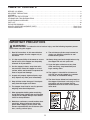
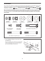
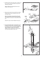
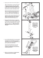
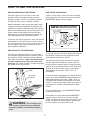
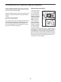
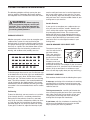
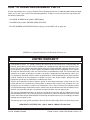
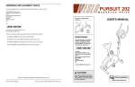
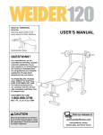
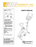
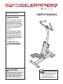
Model No. WEST20020
QUESTIONS?
USERʼS MANUAL
As a manufacturer, we are committed to providing complete
customer satisfaction. If you
have questions, or if there are
missing parts, we will guarantee
complete satisfaction through
direct assistance from our
factory.
TO AVOID DELAYS, PLEASE
CALL DIRECT TO OUR TOLLFREE CUSTOMER HOT LINE.
The trained technicians on our
customer hot line will provide
immediate assistance, free of
charge to you.
1-800-288-4802
CUSTOMER HOT LINE:
Mon.–Fri., 8 a.m.–5 p.m. CST
CAUTION
Read all precautions and instructions in this manual before
using this equipment. Keep this
manual for future reference.
Visit our website at
www.weiderfitness.com
new products, prizes,
fitness tips, and much more!
TABLE OF CONTENTS
BEFORE YOU BEGIN . . . . . . . . . . . . . . . . . . . . . . . . . . . . . . . . . . . . . . . . . . . . . . . . . . . . . . . . . . . . . . . . . . . . . .2
IMPORTANT PRECAUTIONS . . . . . . . . . . . . . . . . . . . . . . . . . . . . . . . . . . . . . . . . . . . . . . . . . . . . . . . . . . . . . . . .3
ASSEMBLY . . . . . . . . . . . . . . . . . . . . . . . . . . . . . . . . . . . . . . . . . . . . . . . . . . . . . . . . . . . . . . . . . . . . . . . . . . . . . . .4
HOW TO USE THE STEPPER . . . . . . . . . . . . . . . . . . . . . . . . . . . . . . . . . . . . . . . . . . . . . . . . . . . . . . . . . . . . . . . .6
STORAGE AND TROUBLESHOOTING . . . . . . . . . . . . . . . . . . . . . . . . . . . . . . . . . . . . . . . . . . . . . . . . . . . . . . . . .7
CONDITIONING GUIDELINES . . . . . . . . . . . . . . . . . . . . . . . . . . . . . . . . . . . . . . . . . . . . . . . . . . . . . . . . . . . . . . . .9
PART LIST . . . . . . . . . . . . . . . . . . . . . . . . . . . . . . . . . . . . . . . . . . . . . . . . . . . . . . . . . . . . . . . . . . . . . . . . . . . . . .10
EXPLODED DRAWING . . . . . . . . . . . . . . . . . . . . . . . . . . . . . . . . . . . . . . . . . . . . . . . . . . . . . . . . . . . . . . . . . . . . .11
HOW TO ORDER REPLACEMENT PARTS . . . . . . . . . . . . . . . . . . . . . . . . . . . . . . . . . . . . . . . . . . . . .Back Cover
LIMITED WARRANTY . . . . . . . . . . . . . . . . . . . . . . . . . . . . . . . . . . . . . . . . . . . . . . . . . . . . . . . . . . . . . .Back Cover
IMPORTANT PRECAUTIONS
WARNING:
To reduce the risk of serious injury, read the following important precautions before using the stepper.
1. Read all instructions in this manual before
using the stepper. Use the stepper only as
described.
9. The resistance cylinders may become hot
during use. Allow the cylinders to cool
before touching them.
2. It is the responsibility of the owner to ensure
that all users of the stepper are adequately
informed of all precautions.
10. Always keep your back straight when using
the stepper. Do not arch your back.
11. If you feel pain or dizziness at any time
while exercising, stop immediately and
begin cooling down.
3. Use the stepper indoors, away from moisture and dust. Place the stepper on a level
surface, with a mat beneath it to protect the
floor or carpet from damage.
12. The stepper is intended for in-home use
only. Do not use the stepper in a commercial, rental, or institutional setting.
4. Inspect and properly tighten all parts regularly. Replace any worn parts immediately.
13. The decal shown below has been placed on
the stepper. If the decal is missing, or if it is
not legible, call our Customer Service
Department toll-free to order a free replacement decal.
5. Keep children under the age of 12 and pets
away from the stepper at all times.
6. The stepper should not be used by persons
weighing more than 250 pounds.
7. Wear appropriate clothing when exercising;
do not wear loose clothing that could become
caught on the stepper. Always wear athletic
shoes for foot protection.
8. Maintain a continuous, smooth motion when
exercising. Always keep your feet on the
pedals when stepping, or the pedals may
become separated from the resistance cylinders, causing serious injury.
2
BEFORE YOU BEGIN
Department toll-free at 1-800-288-4802, Monday
through Friday, 8 a.m. until 5 p.m. Central Time
(excluding holidays). To help us assist you, please
mention the product model number when calling. The
model number is WEST20020.
Thank you for selecting the new WEIDER® AERO
STEPPER. The WEIDER® AERO STEPPER blends
advanced engineering with contemporary styling to
provide you with effective, low-impact workouts in the
convenience and privacy of your own home.
For your benefit, read this manual carefully before
using the stepper. If you have questions after reading this manual, please call our Customer Service
Before reading further, please familiarize yourself with
the parts that are labeled in the drawing below.
Console
Handlebar
Handlebar Post
Upright
Resistance Cylinder
Pedal
Pedal Leg
Stabilizer
WARNING:
Before beginning this or any exercise program, consult your physician.
This is especially important for persons over the age of 35 or persons with pre-existing health problems. Read all instructions before using. ICON assumes no responsibility for personal injury or
property damage sustained by or through the use of this product.
3
ASSEMBLY
Place all parts of the stepper in a cleared area and remove the packing materials. Do not dispose of the packing
materials until assembly is completed. Assembly requires the included allen wrench
and your
own phillips screwdriver
, adjustable wrenches
and rubber mallet
.
Refer to the drawings below to identify the small parts used during assembly. The number in parenthesis below
each part refers to the key number of the part, from the PART LIST on page 10. The second number refers to
the quantity required for assembly. Note: If a part is not found in the parts bag, check to see if it has been
preassembled.
M8 Nylon
Locknut (31)–4
M10 Nylon
Locknut (15)–4
M6 x 16mm Button
Screw (22)–4
Curved
Washer (25)–4
Large M10
Washer (21)–2
M10 x 20mm
Screw (28)–4
M10
Washer (18)–6
M10 x 55mm Carriage Bolt (17)–4
M8 x 65mm Carriage Bolt (24)–2
M8 x 60mm Carriage Bolt (27)–2
1. Press an Adjustable Endcap (5) onto each end of
the Stabilizer (8).
Attach the Stabilizer (8) to the Base (2) with two M8
x 65mm Carriage Bolts (24), two Curved Washers
(25), and two M8 Nylon Locknuts (31).
4
1
2
15
25
5
15
25
8
5
24
2. Identify the Left Pedal Leg (6). Attach a Pedal (11) to
the Left Pedal Leg using the adhesive pad on the
underside of the Pedal.
2
11
Attach a Pedal (11) to the Right Pedal Leg (not
shown) in the same way.
6
3. Apply grease to the left axle on the Base (2). Apply
grease inside the Pedal Leg Bushings (16) in the
Left Pedal Leg (6).
3
Apply
grease
Slide the Left Pedal Leg (6) onto the axle on the
Base (2). Attach the Left Pedal Leg with an M10 x
20mm Button Screw (28) and a Large M10 Washer
(21).
16
Repeat this step to attach the Right Pedal Leg (7).
4. Insert the four M10 x 55mm Carriage Bolts (17) up
through the indicated holes in the Base (2). Slide
the Upright (1) onto the Carriage Bolts. Make sure
that the Upright is angled in the direction
shown. Attach the Upright with four M10 Washers
(18) and four M10 Nylon Locknuts (15).
4
28
2
Apply
grease
16
21
6
1
15
18
5
18
17
2
5. Apply grease to the left axle on the Upright (1).
Apply
grease
5
Slide a Cylinder Spacer (19) and a Resistance
Cylinder (9) onto the left axle on the Upright
(1). Make sure that the curved side of the
Cylinder Spacer is facing the Upright. Attach
the Resistance Cylinder with an M10 x 20mm
Button Screw (28) and an M10 Washer (18).
19
28 18
Raise the Left Pedal Leg (6) and rest it on the
hook on the lower end of the left Resistance
Cylinder (9). Make sure that the hook is in
one of the slots under the Left Pedal Leg.
9
1
9
7
Slots
Repeat this step to attach the other Resistance
Cylinder (9) to the right side of the stepper.
Make sure that the hooks are in the same
position under both Pedal Legs (6, 7).
6. Route the Reed Switch Wire (12) through the
Handlebar Post (3). Attach the Handlebar Post
to the Upright (1) with two M8 x 60mm Carriage
Bolts (27), two Curved Washers (25), and two
M8 Nylon Locknuts (31). Make sure that the
Reed Switch Wire does not get pinched or
damaged.
Hook
6
6
12
3
27
25
25
1
7. Insert the Reed Switch Wire (12) up through the
indicated hole in the Handlebar (4). Attach the
Handlebar to the Upright (1) with four M6 x
10mm Button Screws (22). Be careful to avoid
pinching the Reed Switch Wire.
7
12
Connect the Reed Switch Wire (12) to the
Console (10). Snap the Console onto the
Handlebar (4). Be careful to avoid pinching
the Reed Switch Wire.
8. Make sure that all parts are properly tightened before you use the stepper.
Make sure that
the Reed Switch
Wire does not
get pinched or
damaged during
this step.
31
10
Hole
1
22
6
4
Make sure that
the Reed Switch
Wire does not
get pinched or
damaged during
this step.
HOW TO USE THE STEPPER
HOW TO EXERCISE ON THE STEPPER
HOW TO USE THE CONSOLE
If there is a thin sheet of clear plastic on the console,
remove the plastic. To turn on the console, press the
MODE/RESET button or begin stepping.
Place the stepper on a level surface, with a mat
beneath it. Note: The stepper features precision
hydraulic cylinders. There is a possibility of slight oil
leakage due to the nature of hydraulic cylinders.
Hold the handlebars and step onto the pedals. Begin
stepping, alternately pushing down the right and left
pedals with a smooth, continuous motion. Because the
pedals move independently, you must maintain a continuous motion or both pedals will sink to the floor.
Adjust your pace or the height of your step until you
can comfortably maintain a continuous motion.
To exercise your upper leg muscles, keep your feet flat
on the pedals as you step. To focus on your calf muscles, rise on your toes as you step. Stand erect or lean
forward slightly as you exercise; always keep your
back straight to avoid injury.
HOW TO ADJUST THE RESISTANCE
As you step, the upper half of the display will show the
total number of steps you have completed. A mode
arrow will point to the letters “STPS.”
To change the stepping resistance, first lift the right
and left pedal legs off the hooks on the lower ends of
the resistance cylinders. Move the hooks to different
slots under the pedal legs. Make sure that the hooks
are fully inserted into the same slots under both
pedal legs. The farther the hooks are from the upright,
the greater the resistance will be.
The lower half of the display will show the elapsed
time, the approximate number of calories you have
burned, and your stepping speed, changing from one
mode to the next every few seconds. One mode arrow
will point to the word “SCAN,” and a second mode
arrow will point to the letters “TIME,” “CAL,” or
“STPS/MIN.”
Upright
To view one mode continuously in the lower half of the
display, press the MODE/RESET button until there is a
mode arrow pointing to the letters “TIME,” “CAL,” or
“STPS/MIN” but no mode arrow pointing to the word
“SCAN.” To view all three modes again, press the button until there is a mode arrow pointing to the word
“SCAN.”
Resistance
Cylinder
Hook
Pedal
Leg
To reset the display, press the MODE/RESET button
for about two seconds.
Slots
If the pedals are not moved and the MODE/RESET
button is not pressed for a few seconds, the word
“STOP” will appear in the left side of the display. If the
pedals are not moved and the button is not pressed
for a few minutes, the console will turn off.
WARNING:
The resistance cylinders become very hot during use. Allow the
resistance cylinders to cool before touching
them.
7
TROUBLESHOOTING AND MAINTENANCE
REED SWITCH ADJUSTMENT
Inspect and properly tighten all parts each time you
use the stepper. Clean the stepper using a soft cloth
and mild, non-abrasive detergent.
If the console does
7
not function properly, or if the display
becomes faint, the
batteries should be
replaced. See BATTERY REPLACEMENT at the left.
26
If the console still
does not function
properly, the Reed
12
Switch (12) should
be adjusted. Raise
or lower the Right
Pedal Leg (7) until the Magnet (26) is aligned with the
Reed Switch (12). Refer to the inset drawing. Slide the
Reed Switch (12) in or out slightly. The gap between
the Reed Switch and the Magnet should be about 1/8”.
Make sure that the Magnet will not hit the Reed Switch
when the Pedal Leg is moved. Repeat until the console displays correct feedback.
To prevent damage to the console, keep liquids away
from the console and keep the console out of direct
sunlight.
BATTERY REPLACEMENT
The console requires one type-LR44 watch battery. To
replace the battery, gently pry off the top of the console. Remove the old battery from the holder and
insert a new battery in the same position. Press the
top of the console back into place.
8
CONDITIONING GUIDELINES
The following guidelines will help you to plan your
exercise program. Remember that proper nutrition
and adequate rest are essential for successful results.
WARNING:
Before beginning
this or any exercise program, consult your
physician. This is especially important for
persons over the age of 35 or persons with
pre-existing health problems.
exercise until your heart rate is near the lowest number in your training zone as you exercise. For maximum fat burning, adjust the intensity of your exercise
until your heart rate is near the middle number in your
training zone as you exercise.
Aerobic Exercise
If your goal is to strengthen your cardiovascular system, your exercise must be “aerobic.” Aerobic exercise is activity that requires large amounts of oxygen
for prolonged periods of time. This increases the
demand on the heart to pump blood to the muscles,
and on the lungs to oxygenate the blood. For aerobic
exercise, adjust the intensity of your exercise until
your heart rate is near the highest number in your
training zone.
EXERCISE INTENSITY
Whether your goal is to burn fat or to strengthen your
cardiovascular system, the key to achieving the
desired results is to exercise with the proper intensity.
The proper intensity level can be found by using your
heart rate as a guide. The chart below shows recommended heart rates for fat burning, maximum fat
burning, and cardiovascular (aerobic) exercise.
HOW TO MEASURE YOUR HEART RATE
To measure your heart
rate, first exercise for at
least four minutes.
Then, stop exercising
and place two fingers
on your wrist as shown.
Take a six-second
heartbeat count, and
multiply the result by 10
to find your heart rate. For example, if your six-second
heartbeat count is 14, your heart rate is 140 beats per
minute. (A six-second count is used because your
heart rate will drop rapidly when you stop exercising.)
To find the proper heart rate for you, first find your age
at the bottom line of the chart (ages are rounded off to
the nearest ten years). Next, find the three numbers
above your age. The three numbers are your “training
zone.” The lowest number is the recommended heart
rate for fat burning; the middle number is the recommended heart rate for maximum fat burning; the highest number is the recommended heart rate for aerobic
exercise.
WORKOUT GUIDELINES
Each workout should include the following three parts:
A warm-up, consisting of 5 to 10 minutes of stretching
and light exercise. A proper warm-up increases your
body temperature, heart rate, and circulation in preparation for exercise.
Training zone exercise, consisting of 20 to 30 minutes of exercising with your heart rate in your training
zone. Note: During the first few weeks of your exercise program, do not keep your heart rate in your
training zone for longer than 20 minutes.
Fat Burning
To burn fat effectively, you must exercise at a relatively low intensity level for a sustained period of time.
During the first few minutes of exercise, your body
uses easily accessible carbohydrate calories for energy. Only after the first few minutes of exercise does
your body begin to use stored fat calories for energy.
If your goal is to burn fat, adjust the intensity of your
A cool-down, with 5 to 10 minutes of stretching. This
will increase the flexibility of your muscles and will
help to prevent post-exercise problems.
9
EXERCISE FREQUENCY
workouts. After a few months of regular exercise, you
may complete up to five workouts each week, if
desired. Remember, the key to success is make exercise a regular and enjoyable part of your everyday life.
To maintain or improve your condition, plan three workouts each week, with at least one day of rest between
PART LIST—Model No. WEST20020
Key No. Qty.
1
2
3
4
5
6
7
8
9
10
11
12
13
14
15
16
17
1
1
1
1
2
1
1
1
2
1
2
1
2
1
4
4
4
Description
Upright
Base
Handlebar Post
Handlebar
Adjustable Endcap
Left Pedal Leg
Right Pedal Leg
Stabilizer
Resistance Cylinder w/Bushing
Console
Pedal
Reed Switch /Wire
Frame Endcap
Grommet
M10 Nylon Locknut
Pedal Leg Bushing
M10 x 55mm Carriage Bolt
R1002A
Key No. Qty.
18
19
20
21
22
23
24
25
26
27
28
29
30
31
#
#
#
6
2
2
2
6
2
2
4
1
2
4
2
2
4
1
1
1
Description
M10 Washer
Cylinder Spacer
Handlebar Endcap
Large M10 Washer
M6 x 10mm Screw
Foam Grip
M8 x 65mm Carriage Bolt
Curved Washer
Magnet w/Holder
M8 x 60mm Carriage Bolt
M10 x 20mm Button Screw
Pedal Bumper
Pedal Leg Endcap
M8 Nylon Locknut
Userʼs Manual
Grease Packet
Allen Wrench
Note: “#” refers to a non-illustrated part. Specifications are subject to change without notice. See the back cover
of this manual for information about ordering replacement parts.
10
EXPLODED DRAWING—Model No. WEST20020
20
22
3
27
25
25
18
28
19
15
1
12
18
31
19
9
16
13
21
28
7
26
2
11
6
11
14
13
28
28
18
9
21
10
4
23
16
R1002A
29
22
30
11
17
31
5
25
31
25
8
30
29
22
5
24
HOW TO ORDER REPLACEMENT PARTS
To order replacement parts, call our Customer Service Department toll-free at 1-800-288-4802, Monday through
Friday, 8 a.m. until 5 p.m. Central Time (excluding holidays). To help us assist you, please be prepared to give
the following information:
• The MODEL NUMBER of the product (WEST20020)
• The NAME of the product (WEIDER® AERO STEPPER)
• The KEY NUMBER and DESCRIPTION of the part(s) (see the PART LIST on page 10)
WEIDER is a registered trademark of ICON Health & Fitness, Inc.
LIMITED WARRANTY
ICON Health & Fitness, Inc. (ICON), warrants this product to be free from defects in workmanship and
material, under normal use and service conditions, for a period of ninety (90) days from the date of purchase. This warranty extends only to the original purchaser. ICON's obligation under this warranty is limited to replacing or repairing, at ICON's option, the product through one of its authorized service centers.
All repairs for which warranty claims are made must be pre-authorized by ICON. This warranty does not
extend to any product or damage to a product caused by or attributable to freight damage, abuse, misuse, improper or abnormal usage or repairs not provided by an ICON authorized service center; products
used for commercial or rental purposes; or products used as store display models. No other warranty
beyond that specifically set forth above is authorized by ICON.
ICON is not responsible or liable for indirect, special or consequential damages arising out of or in connection with the use or performance of the product or damages with respect to any economic loss, loss
of property, loss of revenues or profits, loss of enjoyment or use, costs of removal or installation or other
consequential damages of whatsoever nature. Some states do not allow the exclusion or limitation of incidental or consequential damages. Accordingly, the above limitation may not apply to you.
The warranty extended hereunder is in lieu of any and all other warranties and any implied warranties of
merchantability or fitness for a particular purpose is limited in its scope and duration to the terms set forth
herein. Some states do not allow limitations on how long an implied warranty lasts. Accordingly, the above
limitation may not apply to you.
This warranty gives you specific legal rights. You may also have other rights which vary from state to state.
ICON HEALTH & FITNESS, INC., 1500 S. 1000 W., LOGAN, UT 84321-9813
Part No. 80-00023 R1002A
Printed in China © 2002 ICON Health & Fitness, Inc.