1
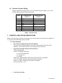
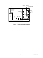
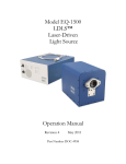
PRELIMINARY
Installation/Operation Guide:
Unity Synchronous Data Option
Data, drawings, and other material
contained herein are proprietary to
Wegener Communications, Inc., and
may not be reproduced or duplicated in
any form without the prior permission of
Wegener Communications, Inc.
When ordering parts from Wegener
Communications, Inc., be sure to include
the equipment model number, equipment
serial number, and a description of the part.
In all correspondence with Wegener
Communications, Inc., regarding this
publication, please refer to UTY4000-007B.
First Edition: February 1999
Revised:
June 2000
WEGENER
COMMUNICATIONS
TECHNOLOGY PARK / JOHNS CREEK
11350 TECHNOLOGY CIRCLE
DULUTH, GEORGIA 30097-1502
(770) 814-4000 FAX (770) 623-0698
R
1. INTRODUCTION
The Unity Sync Data option card provides an IRD with a synchronous data channel output. This
data stream is carried in transport packets whose PID may be assigned in the Wegener UMX4025
at the uplink. This data appears bit-serial on either an RS422 or LVDS output port. The RS422
and LVDS can be activated one at a time or simultaneously.
2. INSTALLATION
2.1 Option Card Install
1. Power-down UTY4000 and remove top cover. Do not lose special screws.
2. See Figure 1, page 5.
3. Expansion module may be installed into either inboard (Module 1) or outboard
(Module 2) position.
3. Remove block-out plate for selected position. Save hardware.
4. Install PWB into selected position. Take precautions against Electro-static
discharge to avoid damage to module.
5. Connect supplied 24-pin cable from J13 on the motherboard to J1 on the Sync Data
Option card.
6. Set jumpers on option card: J9 is the only jumper configurable by the user. If the
sync data card is installed as module 1, place J9 in the dotted position. If the sync
data card is installed as module 2, place J9 in the non-dotted position.
7. Power-up unit and verify that installed option is recognized under
Status_Reports\Parameter_Status menu.
8. Power-down unit and re-install cover.
UTY4000-007
2
2.2 Customer Premises Wiring
Outputs supplied on two RJ45 jacks. Pins are numbered (left-to-right) 1 to 8 as seen
from the open end with tab facing downward.
PIN#
1
2
3
4
5
6
7
8
LVDS SIGNAL
OUTPUT
GND
LD+
LDLS+
LSLC+
LCGND
RS422 SIGNAL
OUTPUT
GND
RD+
RDRS+
RSRC+
RCGND
Table 1. RJ-45 Pin-outs
3. CONTROL AND STATUS INDICATIONS
Note: Sync Data option card may be setup by your network and local control may be disabled. If
so, only the status monitoring will be possible.
3.1 From Terminal
Ÿ
Sync data card setup with local control disabled:
The sync data card setup cannot be accessed via the terminal with local control
disabled. Local control will have to be authorized by the network.
Ÿ
Sync data card setup with local control enabled :
CSD cmd param port
Cmd: R - Set RS422 output state
L - Set LVDS output state
D - Set data rate
P - Set PID
Param:E/D - Enable/disable output ports (used with R & L commands)
64.0 - 6875 Kbps - data rate range (used with D command)
0x0020 - 0x1FFE - PID range (used with P command)
Port: port number (1 or 2)
Ÿ
Sync data card status
3
UTY4000-007
REPORT COMMOND is “r p.” The report will show if any sync data cards are
available. The line will read as follows:
Sync Data Card #(1 or 2): INSTALLED
The SYNC DATA report command is “r sd.” The report will report the sync data
card status in the following form:
FUNCTION CURRENT SETTING
RS422 OUTPUT ENABLED/DISABLED
LVDS OUTPUT
ENABLED/DISABLED
SYNC DATA RATE data rate
PID
PID
STATUS
3.2 From Front-panel
Ÿ
Sync Data Card setup with local control disabled:
The sync data card setup cannot be accessed via the front panel with local control
disabled. The Network must authorize local control.
Ÿ
Sync Data Card setup with local control enabled:
The sync data card can be set via the front panel, if local control is enabled, by using the
menu path HARDWARE SETUP / CONTROL SYNC DATA. Select the parameter you
need to adjust by using the right/left arrows and the <SELECT> key. Use the up/down
arrows to select the desired setting. Press the <ENTER> key to initialize the settings.
Ÿ
Sync Data Card status: To confirm that the Sync Data card option is available via the
front panel follow the menu path STATUS REPORTS / PARAMETER STATUS. Use the
right/left arrow keys to scroll to SYNC DATA.
To view how the sync data card is configured via the front panel follow the menu path
STATUS REPORTS / SYNC DATA STATUS. Use the right/left arrow keys to scroll
through the audio ports configuration.
UTY4000-007
4
Module 1
Rear
UNITY4000
MOTHER
BOARD
Module 2
Screws from
blockout plate
Mounting
Bracket
STANDOFFS
Screws
from kit
J1
Pin 1
P/S
J11
Pin 1
J12
Pin 1
J13
Pin 1
1
Front
Figure 1. UTY4000 Sync Data Kit Installation
5
UTY4000-007