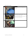
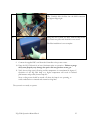
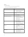
1
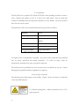
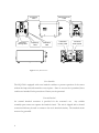
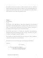
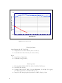
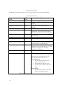
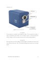
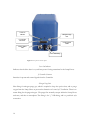
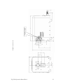
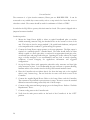
Model EQ-1500
LDLS™
Laser-Driven
Light Source
Operation Manual
Revision 4
May 2011
Part Number DOC-4958
ii
Copyright © 2010 Energetiq Technology Inc. All rights reserved.
Energetiq products are covered by US and foreign patents. All technical information, including
drawings, schematics and specifications contained in this manual are the property of Energetiq
and shall not be reproduced in whole or in part without the written consent of Energetiq. The
content of this manual is subject to change without notice.
Energetiq Technology Inc.
7 Constitution Way, Woburn, MA 01801 USA
Tel. +1 (781) 939-0763
Fax +1 (781) 939-0769
E-mail: [email protected]
http://www.energetiq.com
Table of Contents
Chapter 1...............................................................................................................................1
General Information.................................................................................................................... 1
Safety........................................................................................................................................ 1
Chapter 2........................................................................................................................7
Description .................................................................................................................................... 7
General.................................................................................................................................... 7
Specifications.......................................................................................................................... 7
Identification of Controls .................................................................................................... 9
Controller Unit ...................................................................................................................... 9
Lamp House Unit ............................................................................................................... 13
Chapter 3..................................................................................................................... 16
Installation ................................................................................................................................... 16
Unpacking............................................................................................................................. 16
Facilities Connections......................................................................................................... 16
Installation procedure......................................................................................................... 20
Fiber Cleaning Process....................................................................................................... 24
Chapter 4..................................................................................................................... 27
Operation..................................................................................................................................... 27
Remote Mode ...................................................................................................................... 28
Chapter 5..................................................................................................................... 30
Troubleshooting ......................................................................................................................... 30
iii
iv
Chapter 1
GENERAL INFORMATION
Safety
WARNING
This unit emits ultraviolet (UV) radiation that is harmful to humans.
Avoid exposure to the direct or reflected output beam. Make certain
that the appropriate output beam shields and optics are in place prior
to energizing the unit. All interlocks must be satisfied prior to
operation; failure to do so may lead to hazardous conditions.
CAUTION
The EQ-1500 emits dangerous levels of UV radiation. Even short
exposures to skin or eyes may cause burns.
Ensure that only
authorized personnel are in the vicinity of source during operation.
Personnel in vicinity of operating source should wear protective
eyewear, clothing, and gloves. Lighted UV warning lights and signs
posted on doors to lab areas may help prevent accidental exposure.
EQ-1500 Operation Manual Rev 4
1
WARNING
The EQ-1500 utilizes an internal Class 4 IR laser
capable of causing severe injury to eyes or skin. Do
not open or attempt to service this unit. Contact
Energetiq regarding any problems with the unit.
General Precautions
The output beam from the EQ-1500 should be blocked when not in use with an electronic
shutter or other appropriate beam blocking device. Due to the absorption of the short
wavelength light and the possibility of ozone production, the beam should always be either
directly coupled to a fiber optic cable, or enclosed in an appropriate beam pipe, tube, or
enclosed space. We suggest purging any beam transport space with dry Nitrogen gas, as this is
also required for safe operation of the EQ-1500.
The source must be purged with dry nitrogen gas via the nitrogen input connector on the lamp
head. The unit must be purged for a minimum of 10 minutes prior to operation in order to
ensure that no ozone is created by residual oxygen inside the unit. It is recommended that any
beam transport be purged for a similar amount of time.
The EQ-1500 controller must be connected to an appropriate closed-loop water chiller
system. The water system must be capable of maintaining 0.5gpm at 18°C with a minimum of
200W cooling capacity
The EQ-1500 source must also be cabled correctly and connected to a socket with a protective
earth ground prior to operation. Failure to do so may result in an electrical shock hazard.
Refer to the Installation section of this manual (Chapter 3) for details of the facilities
connections.
2
There are no user-serviceable parts inside the EQ-1500. For any problems encountered during
operation, please refer to the Troubleshooting section of this user manual. If there is a
component failure, do not attempt to open the chassis of the EQ-1500.
The EQ-1500 utilizes a quartz lamp containing a high-pressure gas fill. Explosion of the lamp
and possible injury from flying fragments can occur if the lamp is mishandled. Never attempt
to remove or replace the lamp. If there is a failure of the lamp, the unit must be shipped
back to the factory for refurbishment.
Do not open the chassis of either the lamp unit or the power supply unit. Dangerous
invisible infrared laser beams and hazardous voltages exist inside the units. Opening
the chassis both voids the warranty and exposes the user to dangerous radiation and hazardous
voltages.
CAUTION
The EQ-1500 must be operated for its intended use and as
described in this operating manual. Operation in an un-intended
manner may result in dangerous conditions.
CAUTION
Use of controls or adjustments or executing procedures other
than those specified herein may result in hazardous radiation
exposure.
EQ-1500 Operation Manual Rev 4
3
Laser Information
The EQ-1500 uses a patented (U.S. Patent #7,435,982, others pending) laser drive system to
excite a plasma that radiates in the UV as well as the visible bands. Since the lamp unit
contains an embedded laser, the EQ-1500 is defined as a Laser Product. However, the drive
laser does not exit the system.
The parameters of the non-accessible internal laser are given below in Table 1.
Wavelength
975 nm
Emission Type
CW
Laser Power for classification
<40 mW via 7mm measurement
aperture
Beam Diameter
~25 mm at aperture
Divergence
>100 mRad
Transverse Beam Mode
Highly irregular, diffuse
Table 1: Embedded Laser Parameters
No regular service or maintenance is required. Any service to the system must be performed
only by factory authorized and trained technicians.
To avoid eye injury, under no
circumstances should the user open or modify the lamp unit.
The unit must not be operated if the covers are removed or it is defective in any way. Contact
Energetiq if any problems with the equipment are suspected.
Labels and Safety Notification
The following safety labels appear on the product. Figure 1 shows the location of each label
on the EQ-1500 lamp unit.
UV Hazard warning label – indicates hazardous levels of UV
light are present.
4
Manufacturer’s identification label – gives the manufacturer’s
name and address, and the model, serial number, and date of
manufacture of the equipment.
Explanatory label – states the classification of the laser product.
Class 1 is the lowest hazard level classification.
Certification label – states that the equipment has been tested
and verified to meet the standards indicated.
Interlocked housing label – notifies of a potential hazard when
covers are removed and interlocks failed or defeated.
Protective Ground (Functional Earth) symbol
EQ-1500 Operation Manual Rev 4
5
UV Warning
Label
Interlocked
Housing Label
Explanatory
Label
Manufacturer’s ID
Label
Certification
Label
Interlocked
Housing Label
Functional
Earth Symbol
Figure 1: Safety label locations
Cover Interlocks
The EQ-1500 is equipped with cover interlock switches to prevent operation of the source
without the lamp unit and controller covers in place. Since no user service is permitted, these
switches are intended for the protection of factory service personnel.
External Interlock
An external interlock connector is provided for the customer’s use.
Any suitable
normally-open contact can operate the interlock circuit. The unit is shipped with a shorted
connector which may be used to connect to the user’s interlock circuitry. The interlock circuit
must not be grounded.
6
The interlock circuit must be connected to enable the operation of the unit. Should the
interlock connection open during operation or standby, the source is immediately disabled, and
all light output from the aperture ceases. The source is then latched off and will not restart
until the interlock is restored and the lamp manually restarted.
Chapter 2
DESCRIPTION
General
The EQ-1500 is a DUV lamp system for a wide variety of applications. The lamp features
high brightness, broad-band light from DUV wavelengths through visible and beyond. The
output is very stable, and has a long lifetime before any service is required. The interface is
quite simple, but robust enough for any lab or industrial environment.
The EQ-1500 system consists of a Controller unit, Lamp House unit, interconnecting
signal/power cable, and interconnecting laser fiber optic cable. Connections to AC power,
cooling water, and purge gas are required for operation.
The Controller unit contains the IR laser, laser power supply, laser cooling, a permanently
attached laser fiber optic cable, and control electronics.
The Lamp House unit contains the lamp, igniter, laser focusing optics, and interlocks.
Specifications
DUV Performance
•
Typical output spectrum: see Figure 2.
o Upper, Blue line: typical EQ-1500 output
o Lower, Red line: typical D2 lamp output
EQ-1500 Operation Manual Rev 4
7
Spectral Radiance (mW/mm^2/nm/sr)
100
10
1
0.1
0.01
0.001
180
280
380
480
580
680
780
Wavelength (nm)
Figure 2: Typical output spectrum
Physical Specifications
System Dimensions (H x W x D), Weight
• Lamp House 175 x 142 x 218 mm (6.9 x 5.6 x 8.6 in)
• Controller 142 x 254 x 419 mm (5.6 x 10.0 x 16.5 in)
Weight
• Lamp House 5 kg (11 lbs)
• Controller 6.5 kg (14.3 lbs)
Utility Requirements
•
•
•
•
8
Electrical 100–120/200–240 VAC ±10%, 50/60Hz, 300VA max.
Fuse: 250VAC, 8A Fast
Cooling Water 0.03–0.07 MPa (5–10 psi) differential, 1.9–3.8 lpm (0.5–1 gpm),
18°C inlet temperature, controlled within ± 1.0°C
Purge Gas: Dry nitrogen, grade 6 preferred, 0.14 MPa (20 psig), 1 lpm
Environmental Requirements
Operating
• Temperature: 5–40°C
• Relative Humidity: non-condensing, 80% max. for temperatures up to 31°C,
decreasing linearly to 50% max. at 40°C
• Altitude: 2000 m (6562 ft) max.
• Pollution Degree 2 (normally only non-conductive pollution; occasional,
temporary condensation possible)
• Installation Category II
• Indoor use only
Transport
• Temperature: -5–95°C
• Relative Humidity: non-condensing, 95% max.
Identification of Controls
The following sections show the location of controls and other features, and give an overview
of their functions. Refer to the “Installation” section of this manual (Chapter 3) for more
detailed information.
Controller Unit
Status Indicator
LEDs
Operation
Selector Switch
Figure 3: Controller front panel
EQ-1500 Operation Manual Rev 4
9
Operation Selector Switch
Momentary switch used to start or stop UV light output, or to clear a Fault condition.
Status Indicator LEDs
Lamp controller Status
LEDs
Power
Controller Interlock OK
LED
Color
Green
Green
Lamp House Interlock OK
Green
External Interlock OK
Remote Control
Green
Green
Laser On
Green
Lamp On
Lamp House Overtemp
Green
Red
Lamp Controller Overtemp
Red
Laser Overtemp
Red
Excess Laser Current
Red
Laser Fault
Red
Functional Description
AC power is applied and power switch is on
All interlocks in the Lamp Controller are
satisfied
All interlocks in the Lamp House are
satisfied
External interlock is satisfied
Remote Control has been activated via
connector J6. Local Control via the front
panel Operation Selector Switch is disabled.
Laser current is on (Lamp on command has
been asserted)
Plasma has ignited and is operating
Bulb housing temperature has exceeded 90C
(cooling failure)
Safety interlock for cold plate temperature
has exceeded 70C (cooling failure)
Unit has shut off due because laser
temperature has exceeded 40 degC. Cooling
water flow or temperature for Lamp
Controller is insufficient.
Laser current has exceeded 9A (does not
stop operation)
Indicates that the laser has been disabled
due to a fault. The Controller has requested
laser power, but an IR sensor in Lamp
House did not detect laser power.
Prior to Ignition:
1. The unit has shut down due to a
separate interlock fault
2. The plasma has failed to ignite.
3. A failure has occurred in the laser
fiber.
After Ignition:
1. A failure has occurred in the laser
fiber or laser delivery optics.
Table 2: Front Panel LED functions
10
Interlock
Connector
J4 Remote Sensor
Connector
Laser Connection
to Lamp House
Armored Laser
Fiber (coiled for
storage)
Fuse Drawer
Power On/Off
Switch
Cooling Water
Connections
Power Entry
Connector
Functional Earth
Terminal
J6 Remote
Control Connector
J5 Lamp House
Connector
Cooling Fan
Exhaust
Figure 4: Controller rear panel
Interlock Connector
Connection point for a user-supplied external interlock contact. Contact must be closed or
connector jumpered to enable operation. We recommend that any door or enclosure switches
in the user’s system be wired in series with this interlock connection.
Laser Connection to Lamp House
Connects to the Lamp House to supply laser energy to the lamp via the fiber cable.
J4 Remote Sensor Connector
Connection point for a user-supplied photosensor, when using remote control/remote sensing
mode.
EQ-1500 Operation Manual Rev 4
11
Armored Laser Fiber
Transmits laser energy from the Controller to the Lamp House. Handle the fiber gently and
avoid creating sharp bends or kinks in the cable. Minimum bend radius for the cable is 30 mm
(1.2 in). See instructions in Chapter 3 under “Installation Procedure” for details on inspecting,
cleaning and installing the fiber.
Fuse Drawer
Two AC line fuses are installed in this fuse holder. The fuse type is 250V, 8A, Fast, 5 x 20mm
Power On/Off Switch
This switch is used as a main AC power switch. It can also be used as an emergency off
switch.
Power Entry Connector
The power input connection to the EQ-1500 is made via a standard IEC 3-pin power entry
module. A power cable is included with the system, but any standard cable can be used.
Cooling Fan Exhaust
The internal laser power supply is air cooled. To avoid overheating, do not obstruct this fan
exhaust.
J5 Lamp House Connector
Provides power and control signals to the Lamp House. No connector or cable may be used
with the EQ-1500 other than the one supplied.
J6 Remote Control Connector
Provides access to control and status signals when operating the EQ-1500 in remote control
mode.
Cooling water connections
Standard Swagelok® connectors for cooling water supply and return, providing cooling for the
internal diode laser.
12
Lamp House Unit
Exit Aperture
Mounting Holes
Mounting Holes
(on underside)
Figure 5: Lamp house unit front panel
Exit Aperture
The exit aperture is a standard 1-inch threaded lens holder. The exit aperture also includes a
high UV transmission quartz window. Do not attempt to remove or otherwise disturb this
window. Doing so voids your warranty and may result in unsafe operating conditions
Mounting Holes
The Lamp House may be free standing or mounted rigidly via threaded holes situated on the
front and bottom of the unit. The ¼-20 threaded mounting holes are spaced on a 1-inch grid
pattern.
EQ-1500 Operation Manual Rev 4
13
Laser On
Indicator
Nitrogen Purge
Inlet
J1 Controller
Connector
Cooling Water
Outlet
Cooling Water
Inlet
Laser Fiber Entry
Figure 6: Lamp house unit rear panel
Laser On Indicator
Indicates that the drive laser is on, and laser power is being transmitted to the Lamp House.
J1 Controller Connector
Interface for power and control signals from the Controller.
Nitrogen Purge Inlet
Inlet fitting for nitrogen purge gas, which is required to keep the optics clean, and to purge
oxygen from the Lamp House to prevent the formation of ozone by UV radiation. There is no
return fitting for the purge nitrogen. The purge flow normally escapes within the Lamp House
enclosure, and then to atmosphere. The fitting is for ¼” OD tubing, and is a push-lock style
connection.
14
Cooling Water Inlet/Outlet
Push-lock tube fittings for the Lamp House cooling water.
Laser Fiber Entry
Entry point and strain relief for the laser fiber optic cable. The cable is connected inside the
Lamp House enclosure using a proprietary SMA-type connector. The EQ-1500 system is
shipped with this connection already made.
EQ-1500 Operation Manual Rev 4
15
Chapter 3
INSTALLATION
Installation of the EQ-1500 consists of connecting electrical, water, and gas supplies, and
connecting the lamp output to the user’s equipment.
Unpacking
Upon arrival, start by inspecting all parts of the system for completeness and any damage
incurred in shipping. The EQ-1500 shipping box should contain: 1) EQ-1500 Controller unit,
1) EQ-1500 Lamp House, 1) Lamp House Signal/Power Cable, and 1) 2m IEC power cord.
If any part is missing or appears damaged, contact the manufacturer. Do not attempt to
substitute any parts. There are no user-serviceable parts inside the EQ-1500 Lamp House or
Controller unit.
The EQ-1500 system is shipped with the laser fiber optic cable already connected between the
Controller and Lamp House. Use care during installation and operation to avoid creating
sharp bends or kinks in the cable. Minimum bend radius for the cable is 60 mm (2.4 in).
Facilities Connections
Electrical Service
The EQ-1500 can be operated from 100–120/200–240VAC, single-phase, 50-60Hz. Power
consumption is approximately 200VA during normal operation, 300VA during lamp starting.
The EQ-1500 uses a detachable three-wire standard IEC 60320 C13 cord for connection to
the power source. The cord also provides the connection to the protective earth circuit.
Exposed metal parts of the EQ-1500 are connected to the protective earth ground via the cord
and the outlet ground, providing protection against electrical shock. Never operate the EQ1500 from an outlet without a properly connected protective earth ground.
There is no selection switch for line voltage, it is automatically adjusted internally.
16
Cooling Water
The EQ-1500 requires 1.9–3.8 lpm (0.5–1 gpm) water at a minimum of 0.14 MPa (20 psi).
The temperature must be held at 18 ± 1 degrees C. The pressure drop at 3.8 lpm (1 gpm)
through the cold plate is less than 0.07 MPa (10 psi). There are several thermoelectric and
direct water-to-water chillers that can satisfy these requirements. Tight temperature regulation
is required for tight regulation of the lamp’s output. If there are any questions or concerns,
please contact the manufacturer for recommendations or guidance.
The Lamp House water connection fittings are push-to-connect fittings sized for 3/8” O.D.
tubing. The Controller water connection fittings are 3/8” Swagelok® tube fittings.
The Lamp House and Controller should be connected in series, with the Controller upstream.
See Error! Reference source not found. below.
Water Supply
Water Return
Figure 7: Cooling water circuit layout
Purge Gas
The EQ-1500 requires grade 6 or better nitrogen purge gas. The requirement for purge gas is
a result of the EQ-1500 lamp’s unique performance and operating principles. The EQ-1500
EQ-1500 Operation Manual Rev 4
17
produces UV radiation capable of generating ozone gas when exposed to atmospheric oxygen.
So first and foremost, the nitrogen purge gas is intended to displace any oxygen in the system’s
optical chamber. The optics assembly is in direct contact with this purge gas. UV optics are
quite prone to UV photo contamination. Clean and pure nitrogen from either a dewar or
research-grade N2 bottle is recommended. Do not use any other purge gas. Usage of
clean dry air (CDA) may cause damage to internal optical components, and is likely to
produce ozone gas, which is a potential inhalation hazard.
The fitting is a push-to-connect fitting sized for 1/4” O.D. tubing. The suggested hose to
mate to this fitting is either Nylon: Shore D 50-70, Polyethylene: Shore D 50-196, or Teflon
1/4” O.D. tubing.
There is no return fitting for the purge nitrogen. The purge flow normally escapes within the
lamp unit enclosure, and then to atmosphere.
Optical Interface
The exit aperture consists of a Newport LH-1-5 1.5” lens mount. This incorporates a 1.563-20
thread. Optionally, to utilize the full 0.5 NA output of the EQ-1500, this lens mount can be
removed. With the lens mount removed, the machined mounting holes on the front panel can
be used to interface to the EQ-1500 to external optics. Figure 7 shows the details of the
optical interface. See Figure 8. below.
Any beam transport space should be purged with dry nitrogen to prevent the formation of
ozone from atmospheric oxygen.
18
EQ-1500 Operation Manual Rev 4
19
Figure 7: Optical interface
Plasma Location
External Interlock
The connector is a 2-pin circular connector, Hirose part no. RM12BPE-2PH. It can be
connected to any suitable dry-contact switch, such as a snap switch for a beam line cover or
other door switch. The contact should be rated for a minimum of 15mA at 15VDC.
In order for the EQ-1500 to operate, this circuit must be closed. The system is shipped with a
jumpered connector installed.
Installation procedure
1. Mount the Lamp House rigidly to either an optical breadboard plate or another
suitable mounting structure using the threaded holes on the bottom or front of the
unit. The holes are sized to accept standard ¼-20 optical bench hardware, and spaced
to be compatible with a standard 1” grid mounting hole pattern..
2. Connect the Lamp House output aperture to the user equipment. The light output is
coupled via a standard optical 1” threaded barrel. The beam should always be either
directly coupled to a fiber optic cable, or enclosed in an appropriate beam pipe, tube,
or enclosed space and purged with nitrogen. Operating the source without any output
target or beam transport is not recommended, and may lead to unsafe operating
conditions. Consult Energetiq for applications information and suggested
configurations.
3. Set up the Lamp House with appropriate ultraviolet safety measures and laser light
safety measures in place. It is recommended that any enclosure or aperture-blocking
hardware utilize cover switches wired to the EQ-1500 external interlock circuit.
4. Place the Controller unit no farther than 6 feet from the lamp unit, as the supplied
cable is only 2 meters long. Do not block the air vents at the front or rear of the
Controller.
5. Connect the supplied Signal/Power Cable to the Lamp House and the Controller.
The connectors are polarized to prevent errors in setup. Be sure to screw the attached
flathead connector mounting screws fully with 12 in-lbs torque.
6. Connect cooling water and nitrogen purge gas to the Lamp House. Refer to “Facilities
Requirements” above.
7. Connect cooling water to the Controller unit.
8. Verify that the main power switch on the back of the Controller is in the “OFF”
position.
20
Fiber installation procedure
Step
8.1.
Picture
Description
Using the supplied 1/16” hex driver, remove the screws
securing the lamp house cover. Carefully lift the cover
straight up.
CAUTION: The shielded fiber located on the back of
the controller has a minimum bend radius of 30mm. Use
care not to bend the fiber too tightly.
8.2.
Cut the zip-tie securing the fiber to the back of the
controller and then unwrap the fiber.
8.3
Remove the SMA cap located inside the lamp house.
EQ-1500 Operation Manual Rev 4
21
8.4a
While supporting the end of the fiber, place the strain
relief against the side of the lamp house. You will see
two ‘fingers’ that lock the strain relief in place from the
back side. These will need to slide over the inside surface
of the panel.
8.4b
Rotate the strain relief around the corner while keeping
the locking ‘fingers’ on the inside.
8.4c
Move the strain relief all the way to the left. You should
not be able to pull the strain relief straight out.
8.5
Carefully remove the cap from the end of the fiber. Use
care not to touch the end of the fiber. THE FIBER
END MUST BE KEPT VERY CLEAN.- VERY
IMPORTANT – See section on “Fiber Cleaning” at
the end of this section.
22
8.6
Again, use extreme care not to touch the end of the
fiber. Carefully slide the fiber into the SMA connector
and tighten finger tight.
8.7
Using care not to pinch any wires, slide the lamp house
cover back into place and install the cover screws.
The fiber installation is now complete.
9. Connect the supplied IEC cord from the Controller to the power source.
10. Purge the EQ-1500 unit for at least 10 minutes prior to operation. Failure to purge
the system properly may damage the optics and may produce ozone gas.
11. Verify that cooling water is flowing and the temperature is at maximum 18 degrees C.
Operation of the EQ-1500 lamp at a higher temperature will result in reduced
performance and possibly shorter lamp life.
Note: cooling water should be turned off when the lamp is not operating, to
avoid condensation on internal and external cooling lines.
The system is now ready to operate.
EQ-1500 Operation Manual Rev 4
23
Fiber Cleaning Process
Fiber Cleaning Basics:
• The LDLS laser fibers contain very high power densities, and are susceptible to
damage if the LDLS is operated when the fiber connector is not clean.
• Leave Laser Fiber SMA connected whenever possible
• Minimize the number of fiber connections
• If the SMA fiber must be disconnected, always use a cap on both ends:
– Store caps open side down when possible
– Blow out caps with CDA (Clean Dry Air) prior to use
• Never leave the fiber disconnected without a cap
• Follow the fiber inspection and cleaning process before making an laser fiber SMA
connection
• Operating the LDLS with a contaminated fiber introduces the risk of decreased
performance or damage to the unit
• Always remove AC power from the EQ-1500 before performing a fiber inspection or
cleaning.
Fiber Inspection and Cleaning Process:
Note - Fiber Inspection should only be performed with power removed from the EQ-1500
Power Supply Controller Unit
Figure 6: Fiber Cleaning Process Flowchart
Start
Is fiber end
contaminated?
No
Install Laser SMA
Connector
24
Inspect Fiber end
Inspect Fiber end
Inspect Fiber end
Yes
Clean Fiber
end with
Clean Dry Air
Is fiber end
contaminated?
No
Install Laser SMA
Connector
Yes
Clean Fiber
end with
Cletop
Is fiber end
contaminated?
No
Install Laser SMA
Connector
Yes
Clean Fiber Lint
Free Wipe and
Isopropyl
Alcohol
Fiber Inspection Tools:
Figure 7: Thorlabs
Inspection Scope
CL-200 Handheld Fiber
Figure 8: Westover FVD-2400: Benchtop USB /
PC Operated fiber viewer
Examples of Fiber Images:
EQ-1500 Operation Manual Rev 4
25
Figure 9: Contaminated Fiber end
Fiber Cleaning Tools:
Figure 10: Clean Fiber End
1. Clean Dry Air
2. Dust Off (or similar clean, compressed air)
3. Cletop
www.cletop.com
Cletop Type A SMA cleaner with Blue tape
14100500
Box of 6 Replacement Blue Tape Reels
14100700
4. Lint Free Wipe with Isopropyl Alcohol
5. A modified adapter for the fiber inspection scopes is available through Energetiq.
26
Chapter 4
OPERATION
Once the lamp is set up properly, verify that all personnel that will be in contact with the lamp
system are aware of the potential hazards involved with its operation. It is the responsibility of
the user to verify that the lamp is being used safely.
To start the lamp:
1. Verify that all safety measures are in place, and that cooling water and purge gas are
flowing.
2. Turn on the main power switch on the back of the unit.
3. The lights on the front panel of the Controller will indicate power and interlock status.
Verify that the following indicators are lit:
-
POWER OK
-
CONTROLLER INTLK OK
-
LAMP HOUSE INTLK OK
-
EXTERNAL INTLK OK
4. Push the Operation Selector Switch momentarily up to the LAMP ON position. The
EQ-1500 enters the start mode. While in the start mode, the LASER ON indicators
will light (both on the Controller and the Lamp House). After 60 seconds, the lamp
will ignite and the LIGHT ON indicator will light.
5. If the lamp does not start within approximately 60 seconds, start mode will terminate
(i.e., the lamp stops trying to ignite), and the “Laser Fault” LED will illuminate. If this
happens, push the Operation Selector Switch to OFF / RESET to clear the fault, then
to LAMP ON to try again. [If the lamp still does not ignite after 1 or 2 more attempts,
raise the cooling water temperature to 25°C and try again. Once the lamp ignites,
lower the temperature setpoint back to 18°C for normal operation.]
6. For optimal results (best stability), the EQ-1500 should be allowed to complete a
warmup period of 5 minutes.
Stopping
To shut off the lamp, push the Operation Selector Switch down momentarily to the
OFF/RESET position. The lamp can also be shut off by shutting off the main power switch
on the rear panel.
EQ-1500 Operation Manual Rev 4
27
Opening the interlock chain will also stop the lamp, and the EXTERNAL INTLK OK
indicator will go out. Closing the interlock will not restart the lamp; the fault must be cleared
by pushing the Operation Selector Switch to the OFF/ RESET position, and then the EQ1500 can be started again by pushing the Operation Selector Switch to LAMP ON again.
Cooling water should be shut off when the lamp is not operating, to avoid condensation on
internal and external cooling lines. When shutting down for long periods, the main power
switch may be shut off.
Remote Mode
The EQ-1500 is controlled remotely using the 25-pin connector on the rear of the controller
unit..
Electrical specifications are given below. Pin connections and descriptions of signals are given
in Table 1.
Specifications
Connector
• J6, 25-pin male d-sub
•
Mating connector: standard 25-pin female d-sub, AMP part number 5-747913-2 or
equivalent
Digital inputs
• Type: optocoupler LED input, anode internally connected to +5VDC through a 1K
resistor, cathode connected to input pin
•
Logic: active low (input is on when input pin is pulled to ground return pin)
•
On state current: 3.8 mA
•
Isolation: 5000 VRMS
Digital outputs
• Type: open collector to digital ground
28
•
Logic: active low (output pin is at <0.8V when output is on)
•
Maximum voltage: 15 VDC (internal surge protector clamps at 15V)
•
Maximum load current: 30mA at 5VDC, 12mA at 12VDC
•
Pullup resistor: none
•
Surge- and ESD-protected to 15kV
Control Connector:
Status Signals from Lamp
Controller
Lamp Controller Thermal
Interlock OK
Lamp House Cover
Interlock OK
Lamp House Thermal
Interlock OK
External Interlock OK
Lamp Enable Active
Laser On
Lamp On Status
Laser Overtemp
Laser Fault
Digital Signal Ground
Command Signals from
the tool controller:
Remote Control Enable
Remote Control Enable
Return
Lamp Enable
Lamp Enable Return
Lamp On
Lamp On Return
Unused pins:
J6 DB25 male on Lamp Controller
Description:
Pin
25
3
24
See page 10 for detailed description
Disables Front panel switch
4
23
5
22
6
2
1
11
16
13
14
12
15
8,9,10,17,18,19,20,21
EQ-1500 Operation Manual Rev 4
29
Chapter 5
TROUBLESHOOTING
See below if any problems are encountered in operating the EQ-1500.
Also see page 10 for detailed description of LED signals.
Condition
POWER OK indicator not lit
Action
•
Check line cord and fuse.
•
Check that the main power switch on the
rear panel is in the ON position.
EXTERNAL INTLK OK indicator not lit
•
Check external interlock circuit or jumper
plug
CONTROLLER INTLK OK indicator not lit
•
Internal cover switch in the Lamp Controller
is open. Install Cover.
LAMP HOUSE INTLK OK indicator not lit
•
N2 purge pressure < 15 psi
•
Cover switch is open on Lamp house
•
Laser Fiber SMA connector is not properly
installed at lamp house.
•
Control cable between Controller and Lamp
house is not installed.
LAMP HOUSE OVERTEMP indicator lit
•
Check for sufficient Lamp House cooling
water flow and temperature.
•
Allow system to cool and try operating again.
If condition persists, contact Energetiq.
LASER OVERTEMP or CONTROLLER OVERTEMP
•
indicator is lit
Check for sufficient Controller cooling water
flow and temperature.
•
Ensure that Controller air vents are not
obstructed.
•
Allow system to cool and try operating again.
If condition persists, contact Energetiq.
Lamp fails to ignite
•
Ensure that cable from Controller to Lamp
House is securely attached.
•
Ensure that Controller cooling water flow and
temperature are within spec.
30
•
Laser Fault
Contact Energetiq if condition persists.
Prior to Ignition & No Other Faults:
•
Clear Fault (Operation Selector Switch to
Reset) and attempt again. If Laser Fault
appears immediately, there is likely a
problem with the laser delivery optics;
contact Energetiq.
Prior to Ignition & Other Faults Occur
•
Correct the other indicated fault condition,
clear the fault (Operation Selector Switch to
Reset) and attempt again.
After Ignition (Plasma On):
•
Attempt again. If a Laser Fault appears
immediately, there is a likely a problem with
the Laser delivery optics; contact Energetiq.
EQ-1500 Operation Manual Rev 4
31
Copyright © 2010 Energetiq Technology Inc. All rights reserved.
Energetiq products are covered by US and foreign patents. All technical information, including
drawings, schematics and specifications contained in this manual are the property of Energetiq
and shall not be reproduced in whole or in part without the written consent of Energetiq. The
content of this manual is subject to change without notice.
Energetiq Technology Inc.
7 Constitution Way, Woburn, MA 01801 USA
Tel. +1 (781) 939-0763
Fax +1 (781) 939-0769
E-mail: [email protected]
http://www.energetiq.com
32