1
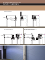
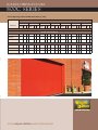
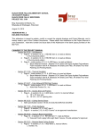
RO L L I N G S E RV I C E D O O R S
WAY N E - DA LTO N C O M M E R C I A L D O O R S Y S T E M S
T HERMOTITE ® 800C SERIE S
800C
ROLLING SERVICE DOORS
INSULATED ROLLING STEEL DOORS CUT YOUR TOTAL ENERGY COST
The Wayne-Dalton 800C Series rolling service door is designed to
meet the tough requirements of virtually any commercial or
industrial application with the added advantage of energy
efficiency. The 800 series offers flexibility in substrate materials
with choices of galvanized or prime steel, stainless steel, or
aluminum.
Color options range from our standard five factory finish colors to a
full range of 180 RAL powder coat choices. Polyurethane insulation
in each slat promotes energy savings and building comfort.
• SIZES UP TO 42' WIDE AND
40' HIGH
• INSULATION R-VALUE = 6.7
• MAX STEEL GAUGE = 18
• FLAT 3" SLAT
• WINDLOAD UP TO 55 PSF
ROLLING SERVICE DOORS
800C SERIES
Popular in both interior and exterior applications,
the Wayne-Dalton 800C Series insulated rolling service
door features a galvanized, pre-painted curtain of
minimum 22-gauge steel. 800C Series doors are wind
load rated at 20 PSF. An optional wind load rating of
up to 55 PSF is available to cover your Florida and
Dade County windload requirements.
Materials & Construction
Wayne-Dalton’s 800C Series rolling doors are
composed of flat slats that provide a natural
water-shed, helping to reduce corrosion.The slats
are designed with free-acting interlocking joints
that permit easy articulation when the door coils.
The 800C Series features a strong double-angle
bottom bar that reinforces the lower edge of the
curtain against wind pressure and permits varied
lock, astragal, and safety edge options. This bottom bar is designed for easy installation and does
not require fasteners protruding into the guide
openings, so the bottom bar does not interfere
with door operation.
Counterbalance assembly consists of a spring
barrel which serves as load-carrying beam. It encases
the counterbalance mechanism and provides the
axis around which the curtain coils. (Deflection is
limited to 0.033" per lineal foot of span.) If
required, barrel rings of malleable iron or stamped
steel may be provided to assure proper
counterbalance. Oil-tempered, torsion-type
counterbalance springs are wound from
heat-treated steel, providing accuracy in balancing
the door. Barrel plugs connect ends of springs to
barrel and tension rod. Tension rod of steel
shafting holds fixed ends of springs and carries
torsion load of spring counterbalance.
Spring tension adjusting wheel is normally mounted
outside the bracket on end of tension rod. Inside
adjusting wheel for tight side-room applications is
available in limited sizes.
Slat Profile
Standard Weatherseal Applications
The hood cover encloses the curtain coil and
counterbalance mechanism. Slat hoods are
available on blue, brown, beige, and white doors.
Available Options
•
•
•
•
•
•
•
•
•
•
•
Vision Slats/Panels
Safety Edges
Drop Stop Device
Exhaust Ports
Sloping Bottom Bars
Powder Coated
Motor Operators
Cable Reels
Mullions
Thru-Wall Operation
Stainless Steel or Aluminum Finishes
To close space between curtain
and guides at jambs, flexible strip on
guides contacts flat surface of curtain.
Bottom bar with weatherseal
To reduce air infiltration at top of
door, hood baffle attached to hood
extends full width of door. Optional
lintel weatherstripping will further
reduce air passage when attached to the
header.
www.wayne-dalton.com/commercial
ROLLING SERVICE DOORS
8 00 C SERIES
X
X
2"
MANUAL OPERATION
ADJUSTING
WHEEL
8"
D
Y
ELEVATION
2"
Y
D
LINTEL
B
L
OPENING DIMENSION "F"
HOOD
SECTION (UNDER LINTEL)
SECTION
BRACKET MOUNTED POWER UNIT
Y
POWER
UNIT
Y
16"
POWER
UNIT
Y
ELEVATION
SECTION (UNDER LINTEL)
ANGLE OR ROLLED GUIDES – FACE MOUNTED TO MASONRY
W
2"
X
26"
16"
D
Y
B
R
D
LINTEL
OPENING HEIGHT "F"
EMERGENCY
HOIST
HOOD
L
X
ADJUSTING
WHEEL
2"
POWER
UNIT
SECTION
ANGLE GUIDES – MOUNTED BETWEEN JAMBS
OPENING WIDTH "A"
800C Series Door
1/4"+GD
OPENING WIDTH "A"
1/4"+GD
ANGLE OR ROLLED GUIDES – FACE MOUNTED TO STEEL
GD
2-3/4"
3-1/4"
WIDTH
TO 28'0"
WIDTH
TO 30'0"
WIDTH
JAMB
JAMB
L
GD
CLEAR OPENING
GD
R
ROLLED GUIDES – MOUNTED BETWEEN JAMBS
OPENING WIDTH "A"
JAMB
1/4"+GD
OPENING WIDTH "A"
COMMON GUIDE MOUNTING OPTIONS
1/4"+GD
JAMB
L
GD
CLEAR OPENING
GD
R
ROLLING SERVICE DOORS
8 0 0 C SERIES
X
X
2"
CHAIN HOIST OPERATION
ADJUSTING
WHEEL
Y
D
ELEVATION
2"
Y
SECTION (UNDER LINTEL)
SECTION
THRU-WALL MOUNTED POWER UNIT
Note: 20" sideroom required on opposite door side for power unit
2"
Y
ADJUSTING
WHEEL
Y
8"
2"
WALL MOUNTED POWER UNIT
D
8.5"
HAND CHAIN
B
LINTEL
L
OPENING DIMENSION "F"
HOOD
POWER
UNIT
2"
2"
HOOD
2"
HOOD
X
POWER
UNIT
X
ADJUSTING
WHEEL
LINTEL
WALL SLOT
EMERGENCY
HOIST
ELEVATION
SECTION
D
20"
Note: power unit is on opposite
side of wall.
ELEVATION
ROLLER
CHAIN
THRU
WALL
SECTION
D
L
B
EMERGENCY
HOIST
LINTEL
B
L
ROLLING SERVICE DOORS
8 0 0 C SERIES
General Operating Clearances 800C Series Doors (3" slats)
WIDTH A
TO 24'0"
TO 16'0"
10'0"
X &Y
R
L
18-1/2" 91⁄16" 71⁄16"
10'0" TO 11'0"
X &Y
20"
R
L
91⁄16" 71⁄16"
11'0" TO 13'6"
X &Y
TO 24'0"
TO 16'0"
18-1/2" 9 ⁄16" 7 ⁄16"
16'0" TO 24'0"
1
20"
9 ⁄16" 7 ⁄16"
1
1
L
13'6" TO 17'6"
X &Y
FACE MOUNTING
R
L
13'6" TO 19'0"
X &Y
R
L
17'6" TO 22'0"
X &Y
R
L
19'0" TO 22'0"
X &Y
R
L
CHAIN HOIST OPERATED
22"
16'0" TO 24'0"
1
R
OPENING HEIGHT
22"
91⁄16" 71⁄16"
24"
91⁄16" 71⁄16"
MOTOR OPERATED
91⁄16" 71⁄16"
24"
NOTE: Dimensions are for general reference
only and not for construction purposes.
www.wayne-dalton.com/commercial
91⁄16" 71⁄16"
24"
24"
91⁄16" 71⁄16"
91⁄16" 71⁄16"
26"
91⁄16" 71⁄16"
26"
91⁄16" 71⁄16"
26"
91⁄16" 71⁄16"
26"
91⁄16" 71⁄16"
ROLLING SERVICE DOORS
T HERMOTITE ® 800C SERIES
Note to specifiers: Words in brackets indicate frequently specified and highly recommended options.
PART I – GENERAL
1.01 Work Included
A. The opening will be equipped withWayne-Dalton
800C Series rolling doors.
1.02 Related Work
A. Opening preparation, miscellaneous or structural
metal work, access panels, finish or field painting,
field electrical wiring, wire, conduit, fuses, and
disconnect switches are in the Scope ofWork of
other divisions or trades.
1.03 Reference Standards
A. ANSI/DASMA 203 – American National
Standards
Institute Specifications for non-rated fire rolling doors
published by Door & Access Systems Manufacturers
Association International.
B. ASTM A123 – Zinc [hot-dipped galvanized] coatings
on iron and steel products.
C. ASTM A229 – Steel wire, oil-tempered for
mechanical springs.
D ASTM A-653-94 – Steel sheet, zinc-coated
[galvanized] by the hot-dipped process,
commercial quality.
E. ASTM E330 – Structural performance of exterior
windows, curtain walls, and doors by uniform static air
pressure difference.
F. ASTM E413-87 – Sound transmission class
acoustical performance value = 22.
1.04 Quality Assurance
A. Rolling doors and all accessories and components
required for complete and secure installations shall be
manufactured as a system from one manufacturer.
1.05 Systems Description
A. Rolling Door:Type:
Model 800C
B. Mounting: [steel] [wood] [masonry] jambs
C. Operation: [manual push-up] [crank] [chain hoist]
[motor] [motor with chain hoist]
D. Material: Galvanized steel with polyester finish paint
1.06 Submittals
A. Shop Drawings: Clearly indicate the following:
1. Design and installation details to withstand
standard windload.
2. All details required for complete operation
and installation.
3. Hardware locations.
4. Type of metal and finish for door sections.
5. Finish for miscellaneous components and
accessories.
B. Product Data: Indicating manufacturer’s product
data, and installation instructions.
1.07 Delivery, Handling, Storage
A. Deliver products in manufacturer’s original
containers,dry,undamaged, seals and labels intact.
B. Store and protect products in accordance with
manufacturer’s recommendations.
1.08 Warranty
A. Standard manufacturer’s one year warranty against
defects in material and workmanship.
PART I I – PRODUCTS
2.01 Curtain
A. Curtain will be composed of interlocking #14 flat slats
[22, 20,18 gauge galvanized steel] [16 B&S aluminum]
[22, 20 stainless steel] slats with [24 gauge][22 gauge
B&S aluminum] back slats, roll-formed per ASTM
standards. The area between the #14 exterior slat
and the back slat will be filled by polyurethane
insulation, R-value of 6.7 (U = 0.15). Curtain designed
to withstand a 20 PSF windload. Ends of
alternate/continuous slats will be fitted with metal
endlocks/windlocks.
B. Bottom Bar will consist of two equal steel
[stainless steel] [aluminum] angles, .121" minimum
thickness, to stiffen curtain, with astragal. When
required for additional security, provide [slide bolts]
[cylinder locks] on the bottom bar operable from
[coil side] [both sides].
2.02 Guides
A. Guides will be roll-formed steel channel bolted to
angle or structural grade, three angle assembly of
steel [stainless steel] [aluminum] to form a slot of
sufficient depth to retain curtains in guides to achieve
20 PSF windload standard. Guides may be provided
with integral windlock bars and removable bottom
bar stops.
2.03 Brackets
A. Brackets will be of 3/16” [1/4"] minimum thick steel
plates, with permanently sealed ball bearings. Designed
to enclose ends of coil and provide support for
counterbalance pipe at each end.
2.04 Counterbalance
A. Curtain to be coiled on a pipe of sufficient size to
carry door load with deflection not to exceed .033"
per foot of door span and to be correctly balanced by
helical springs, oil tempered torsion type. Cast iron
barrel plugs will be used to anchor springs to tension
shaft and pipe.
2.05 Hood
A. Hood will be minimum 24-gauge [aluminum,
22 gauge B&S] [galvanized] [stainless steel] sheet
metal, flanged at top for attachment to header and
flanged at bottom to provide longitudinal stiffness.
Hood will enclose curtain coil and counterbalance
mechanism. A flexible hood baffle is included.
bottom bar to [stop and reverse] the door
when it contacts an object during the closing cycle.
2.08 Weatherstripping
A. Doors will include bottom astragal, surface guide
weatherstrip, and internal hood baffle weatherstrip.
Optional lintel brush weatherstrip available.
2.09 Locking
A. [Manual lift-up doors will have interior slide-bolts
suitable for padlocks by others.] [Chain-hoist door
will have chain keepers suitable for padlocks by
others.] [Electric-motor operation doors will lock
through the operator gearing.] [Cylinder locks can
be provided with the doors.]
Note: When specifying locks on electric-motor operated
doors, electric interlocks should also be specified to
prevent operation when lock bolts are engaged in the
guides, thus preventing damage to the curtain
and/or operator.
2.10 Windload
A. Windload – minimum 20 psf per DASMA 102-2003
and as required by local codes.
PART III – EXECUTION
3.01 Installation
A. General:
1. Install doors in accordance with manufacturer’s
instructions and standards. Installation shall be by
an authorizedWayne-Dalton representative.
2. Verify that existing conditions are ready to receive
rolling door work.
3. Beginning of rolling door work means acceptance
of existing conditions.
B. Install door complete with necessary hardware, jamb
and head mold strips, anchors, inserts, hangers, and
equipment supports in accordance with final shop
drawings, manufacturer’s instructions, and as specified
herein.
C. Fit, align and adjust rolling door assemblies level and
plumb for smooth operation.
D. Upon completion of final installation, lubricate, test and
adjust doors to operate easily, free from warp, twist or
distortion and fitting for entire perimeter.
Note: Architect may consider providing a schedule when
more than one rolling door or opening type is
required.
2.06 Finish
A. Shop coat of rust inhibitive primer on non-galvanized
surfaces and operating mechanisms. Guides and
bracket plates will be coated with a flat black prime
paint. Aluminum finish to be [mill] [204R1 clear
anodized] [bronze anodized]. Stainless steel finish
available. Curtain color will be [white] [blue] [gray]
[beige] [brown] (white, blue, beige, brown only
available as 22 gauge). Powder coating is available in
180 colors.
2.07 Operation
A. Door will be operated by means of [manual, lift-up]
[chain hoist with gear drive reduction] [awning crank]
[wall crank box] [motor operation]. Optional
[electrical] [pneumatic] sensing edge to be attached to
Because of continuing product improvements, we reserve the right to change the product specifications and designs without prior notice.
Distributed By:
www.wayne-dalton.com/commercial
For technical information, visit:
© 2008 Wayne-Dalton Corp. • One Door Drive • Mt. Hope, Ohio 44660 • 800-255-3046
Mt. Hope, OH • Dalton, OH • Trail, OH • Pensacola, FL • Portland, OR
Printed in U.S.A.
Item #333068 Revised 4/2008