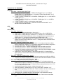
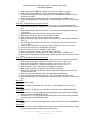
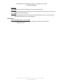
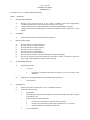
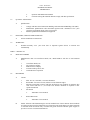
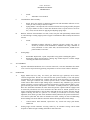
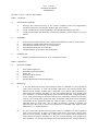
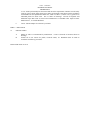
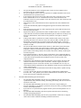
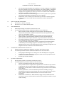
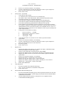
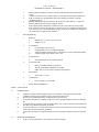
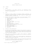
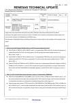
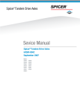
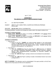
1
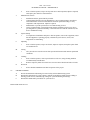
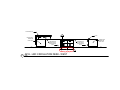
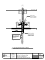
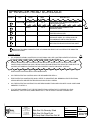
BLACK RIVER FALLS ELEMENTARY SCHOOL
410 COUNTY ROAD A
BLACK RIVER FALLS, WISCONSIN
PROJECT NO. 3164
Bray Associates Architects, Inc.
Milwaukee & Sheboygan, Wisconsin
August 14, 2015
ADDENDUM NO. 2
BUILDING PACKAGE
This addendum is issued to explain, modify or correct the original drawings and Project Manuals, and is
hereby made a part of the Contract Documents. Please attach this Addendum to the Project Manual in
your possession. Insert the number and issue date of this Addendum in the blank space provided on the
Bid Form.
CHANGES TO THE PROJECT MANUAL
- Section 04 20 00 – Unit Masonry
1. Page 5 – in section 2.2, D, 1. REVISE item d. to read as follows:
d. Running bond pattern
2. Page 5 – in section 2.2, D, 2. REVISE item d. to read as follows:
d. Running bond pattern
3. Page 2 – under section 2.10, A, 8. ADD item c. to read as follows:
c. Bayer Material Science – Bayseal CCX Closed Cell Spray Applied Polyurethane
Foam Insulation with W.R. Meadows Air Shield Joint Filler, Air Shield Thru Wall
Plashing and Pointing Mastic.
-
Section 07 21 00 – Thermal Insulation
1. Page 4 – under section 2.1, G, 8. ADD item a. to read as follows:
a. Bayer Material Science – Bayseal CCX Closed Cell Spray Applied Polyurethane
Foam Insulation with W.R. Meadows Air Shield Joint Filler, Air Shield Thru Wall
Plashing and Pointing Mastic.
-
Section 07 53 27 – Fully Adhered EPDM Roof System
1. Page 5 – under section 2.2, A, 1. ADD item c. to read as follows:
c. Mule-Hide Product Co., Inc.
-
Section 08 31 16 – Access Door and Frames
1. Page 2 – in section 2.2, A, 3. ADD items l. and m. to read as follows:
l. 18” x 18” door size.
M. 18 1/8” x 18 1/8” opening size.
-
Section 08 33 25 – Coiling Service Doors
1. ADD specification section “08 33 25 COILING SERVICE DOORS”.
-
Section 08 71 00 – Finish Hardware
1. Page 6 – in section 2.2, A. OMIT item 2.
2. Page 8 – in section 2.10, N. ADD “Dorma” as an approved manufacturer.
-
Section 09 29 00 – Gypsum Board Assemblies
1. Page 12 – in section 3.7, E. REVISE item 11. read as follows:
11. Textured Finish: Apply USG Light Sand Texture. Provide samples for approval.
-
Section 09 53 23 – Modular Metal Ceiling System
1. Page 2 – in section 2.1, A, 1. ADD items c. read as follows:
c. Gordon, Inc.
3164 Black River Falls Elementary School – Addendum #2 / Page 2
BUILDING PACKAGE
-
Section 09 68 16 – Carpet
1. Page 4 – in section 2.1, E. REVISE item 2. to read as follows:
2. Tile Size: 1 m x 1 m (39.4” x 39.4”)
-
Section 09 84 33 – Sound Absorbing and Tackable Wall Panels
1. Page 2 – in section 2.1, A, 1. ADD items p. and q. to read as follows:
p. Lamvin Inc,
q. MBI Products
2. Page 2 – in section 2.1, B, 1. ADD items p. and q. to read as follows:
p. Lamvin Inc,
q. MBI Products
-
Section 09 84 35 – Sound Reflecting Treatment
1. Page 2 – in section 2.1, A. ADD items 9. to read as follows:
9. MBI Products
-
Section 10 14 02 – Exterior Cast Aluminum Signage
1. Page 2 – in section 2.3. REVISE item A. to read as follows:
A. BLACK RIVER FALLS ELEMENTARY; 12” letters.
-
Section 10 28 00 – Toilet Accessories
1. Page 2 – in section 2.4, K. REVISE “Toilet Room Accessory Schedule; Mark ‘M’ ” as
“Toilet Room Accessory Schedule; Mark ‘S’ ”.
-
Section 11 40 00 – Food Service Equipment
1. Page 2 – in section 2.0. OMIT item 33.
-
Section 11 66 26 – Safety Wall Pads
1. DELETE Specification Section “11 66 26 – SAFETY WALL PADS” in its entirety, and ADD
the new Specification Section “11 66 26 – SAFETY WALL PADS” issued with this
addendum.
-
Section 23 09 00 – Building Automation System for HVAC
1. Page 2 – in section 2.1 “VARIABLE FREQUENCY DRIVES”, ADD the following
acceptable manufacturers to paragraph 2.1:
J. Trane Tracer SC installed by Trane Company
-
Section 28 33 23 – Wireless Clock System
1. DELETE Specification Section “28 33 23 – WIRELESS CLOCK SYSTEM” in its entirety,
and ADD the new Specification Section “28 33 23 – WIRELESS CLOCK SYSTEM” issued
with this addendum
-
Section 32 31 21 – Aluminum Louver Gates
1. Page 2 – in section 2.3, B. REVISE item 2. to read as follows:
2. 5” square aluminum corner post.
2. Page 2 – in section 2.3, B, 3. REVISE “Nominal Opening Size: 8’+/- wide by 8’-0” high” as
“Nominal Opening Size: 9’+/- wide by 8’-0” high”.
3. Page 2 – in section 2.3, B, 4. REVISE “Nominal Opening Size: 12’+/- wide by 8’-0” high”
as “Nominal Opening Size: 13’+/- wide by 8’-0” high”.
173 N. B R O A D W A Y σ
M I L W A U K E E , WI 53202 σ
www.brayarch.com
P H O N E 414.226.0200
3164 Black River Falls Elementary School – Addendum #2 / Page 3
BUILDING PACKAGE
CHANGES TO THE DRAWINGS
GENERAL:
- Sheet G0.2 – General Notes & Wall Types
1. In “Wall Type B&B*”, REVISE note “6” METAL STUDS @ 24” O.C.” as “6” METAL
STUDS @ 16” O.C.”, and REVISE note “3” SOUND ATTENUATION BLANKET” as “6”
SOUND ATTENUATION BLANKET”.
2. In “Wall Type C&C*”, REVISE note “3 5/8” METAL STUDS @ 24” O.C.” as “3 5/8” METAL
STUDS @ 16” O.C.”.
3. In “Wall Type D&D*”, REVISE note “3 5/8” METAL STUDS @ 24” O.C.” as “8” METAL
STUDS @ 16” O.C.”.
4. In “Wall Type D&D*”, OMIT 7 3/4" dimension at top of detail.
5. In “Wall Type F&F*”, REVISE note “3” SOUND ATTENUATION BLANKET” as “8”
SOUND ATTENUATION BLANKET”.
CIVIL:
- None
STRUCTURAL:
- Sheet S0.4: Plan Details
1. Detail 9/S0.4: Change the dimension 1’-8” to 1’-8 ¼”.
2. Detail 11/S0.4: Change the title from CP-03 PIER DETAIL to CP-11 PIER DETAIL.
3. Detail 13/S0.4: Change the two 4” dimension to 3”. Change the 1’-3” dimension to 1’-2”.
Change the vertical column GRID mark to A24. Change the bottom horizontal column
GRID mark to AC. Change the top horizontal column GRID mark to AD.
4. Detail 14/S0.4: Change the title from CP-12 PIER DETAIL TO CP-14 PIER DETAIL.
Change the vertical column GRID mark to A15.1. Change the bottom horizontal column
GRID mark from AV to AU.
- Sheet S1.4: Enlarged Foundation Plan – Area ‘A’
1. Move column grid A18 0’-2 ½” South East. Add 2 ½” to all adjacent dimensions North
West of the grid line. Subtract 2 ½” to all adjacent dimensions South East of the grid line.
2. At column grid AL-A14: Add the plan detail mark 11/A0.4.
3. At column grid AT-A15.1: Add the word SIMILAR to the plan detail mark 3/S0.4.
4. At column grid AV-A15.1: Add the word SIMILAR to the plan detail mark 4/S0.4.
5. Concrete Pier Schedule: Change the note TOP OF CONC PIER ELEVATION 99’-8” UNO
to TOP OF CONC PIER ELEVATION 99’-4” UNO.
6. At Stair S102: Add concrete platform. Add Section mark 18/S5.1. Change Section
marks 3/S5.10 to 3/S5.10 SIM. Add the words RAISED CONCRETE PLATFORM SEE
DTL AND ARCH.
- Sheet S1.5: Enlarged Foundation Plan – Area ‘B’
1. At the North East exterior wall of the Gym: Change the section mark 1/S5.14 to 5/S5.13.
2. Concrete Pier Schedule: Change the note TOP OF CONC PIER ELEVATION 99’-8” UNO
to TOP OF CONC PIER ELEVATION 99’-4” UNO.
- Sheet S1.6: Enlarged Second Floor Framing Plan – Area ‘A’
1. Move column grid A18 0’-2 ½” to the South East. Add 2 ½” to all adjacent dimension
North West of the grid line. Subtract 2 ½” to all adjacent dimension South East of the grid
line. Near column grid lines AK-A17: Change the beam spacing dimensions from 7’-2 ½”
to 7’-3 ¾” and 5’-8 5/8” to 5’-6 1/8”.
2. At the South East wall of the elevator: Add the lintel mark L-02.
3. Steel Lintel Schedule: Add the Mark L-02. Type A, Size W8x10, PL/REINF ¼”x7”.
4. Non Load Bearing Masonry Lintel Schedule: Add the schedule, refer to the revised sheet
S1.6.
5. At the Stair S102: Change the stair landing joist size for C4x4.5 to C6x8.2.
6. At the Stair S101: Respace the C5x6.7 joist as shown on the addendum drawings.
- Sheet S1.7: Enlarged Second Floor Framing Plan- Area ‘B’
1. Add all line work relating to steel beams and steel girders. Refer to the revised sheet
S1.7.
173 N. B R O A D W A Y σ
M I L W A U K E E , WI 53202 σ
www.brayarch.com
P H O N E 414.226.0200
3164 Black River Falls Elementary School – Addendum #2 / Page 4
BUILDING PACKAGE
-
-
-
-
-
2. Near column grid lines BE-B18: Change the section mark 6/S5.4 to 15/S5.2.
3. Near column grid lines BH-B18: Change the section mark 5/S5.4 to 16/S5.2.
4. At Stair S103: Respace the C5x6.7 joist as shown on the addendum drawings. Add the
header size C12x20.7.
5. Steel Lintel Schedule: Add the Mark L-02. Type A, Size W8x10, PL/REINF ¼”x7”.
6. Non Load Bearing Masonry Lintel Schedule: Add the schedule, refer to the revised sheet
S1.7.
Sheet S1.8: Enlarged Roof Framing Plan-Area ‘A’
1. Move column grid A18 0’-2 ½” to the South East. Add 2 ½” to all adjacent dimension
North West of the grid line. Subtract 2 ½” to all adjacent dimension South East of the grid
line.
2. Near the North East corner of the elevator: Change the joist seat depth dimension from
[2”] to [2 5/8”].
3. At the South West wall of the elevator: Add the lintel mark L-02.
4. Near column grid AL-A5: Add a roof drain “RD” and frame.
5. Near column grid AL-A9: Add a roof drain “RD” and frame.
6. Between columns at grid lines AD-A24, AG-A24 and AK-A24: Add two grits HSS8x4x1/4
(122’-8”).
7. At column grid lines AN-A15.1 and AG-A15.1: Change the top of steel elevation from
124’-4” to 124’-0”.
8. At column grid lines BL-B3: Change top of steel elevation from 128’-5 ½” to 128’-8”.
9. At column grid lines AF-A4: Omit Section mark 5/S5.4.
10. At column grid lines AE-A7: Add Section mark 5/S5.4.
11. Near column grid lines AG-A3: Add the Elevation mark S4.1.
12. Steel Lintel Schedule: Add the Mark L-02. Type A, Size W8x10, PL/REINF ¼”x7”.
13. Non Load Bearing Masonry Lintel Schedule: Add the schedule, refer to the revised sheet
S1.8.
Sheet S1.9: Enlarged Roof Framing Plan-Area ‘B’
1. At the North East exterior wall of the Gym: Change the section mark 1/S5.14 to 5/S5.13.
2. Near column grid BD-B15: Change the elevation 128’-11 3/16” to 128’-11 1/8”.
3. Near column grid BK-B23: Change the elevations 129’-2 3/8” to 129’- 2 5/8”.
4. Near column grid BM-B15: Change the elevation 128’’11 9/16” to 129’- 11 ½”.
5. Near North end of Gym: Change the note 44LHSP1 to 48LHSP1.
6. Near Center of the Gym: Change the note 44LHSP2 to 48LHSP2.
7. Near the South West wall of the Gym: Add an Angle Frame below the Roof Hatch and
relocate one 16K3 joist.
8. Near column grid lines BF-B18: Resize and relocated roof hatch frame.
9. Steel Lintel Schedule: Add the Mark L-02. Type A, Size W8x10, PL/REINF ¼”x7”.
10. Non Load Bearing Masonry Lintel Schedule: Add the schedule, refer to the revised sheet
S1.9.
Sheet S5.1:
1. Add Section 18/S5.1.
Sheet S5.4:
1. Section 22/S5.4: Change the note TOS 123’-4” to TOS VARIES 123’-4” TO 123’-0”.
Sheet S5.6:
1. Section 5/S5.6: Change the notes 44LHSP1 to 48LHSP1 and 44LHSP2 to 48LHSP2.
Sheet S5.10:
1. Section 1/S5.10: Turn the metal floor deck 90 Degrees to the direction shown, eliminate
the beam and the note BEAM SEE PLAN.
2. Section 2/S5.10: Turn the metal floor deck 90 Degrees to the direction shown, eliminate
the beam and the note BEAM SEE PLAN.
Sheet S5.11:
1. Section 2/S5.11: Omit the wide flange beam at the roof and omit the note W BEAM SEE
PLAN.
Sheet S5.12:
1. Section 1/S5.12: Add the HSS8x4x1/4 Girt, add the bond beams and reinforcing, change
the top of wall elevation as shown on the revised section.
173 N. B R O A D W A Y σ
M I L W A U K E E , WI 53202 σ
www.brayarch.com
P H O N E 414.226.0200
3164 Black River Falls Elementary School – Addendum #2 / Page 5
BUILDING PACKAGE
2. Section 2/S5.12: Change the note TOS 123’-4” to TOS VARIES 123’-4” TO 123’-0”.
Change the vertical dimension 1’-4” to VARIES 1’-8” TO 1’-4”.
ARCHITECTURAL:
- Sheet A1.3 – First Floor Plan – Unit A
1. CLARIFICATION – added dimensions and note to concrete risers below stairs – see
attached revised sheet A1.3.
2. CLARIFICATION – added note to plan for display case – see attached revised sheet
A1.3.
3. REVISED dimension string in reception to dimension to column grid line A16 – see
attached revised sheet A1.3.
4. CLARIFICATION – added callout and revised note at cooler/freezer in kitchen – see
attached revised sheet A1.3
5. REVISE location of column line A18 and column to match structural change (see above
structural revision) – see attached revised sheet A1.3.
- Sheet A1.4 – First Floor Plan – Unit B
1. ADDED additional locations to receive corner guard – see attached revised sheet A1.4
- Sheet A1.5 – Second Floor Plan – Unit A
1. ADDED additional locations to receive corner guard – see attached revised sheet A1.5
- Sheet A1.6 – Second Floor Plan – Unit B
1. ADDED additional locations to receive corner guard – see attached revised sheet A1.6
- Sheet A1.7 – Roof Plan
1. ADDED additional roof drains – see attached revised sheet A1.7
2. ADDED roof ladder to roof plan – see attached revised sheet A1.7
3. ADDED detail 2/A1.7 for roof ladder – see attached revised sheet A1.7
4. ADDED areas of tapered insulation to roof plan – see attached revised sheet A1.7
- Sheet A1.8 – Enlarged Stairs and Toilet Room Plans
1. REVISE drawing title and added callout for 11/A1.8 – see attached revised sheet A1.8.
2. ADDED double robe hook at CD TLT/SHWR in 5/A1.8 – see attached revised sheet A1.8.
- Sheet A3.2 – Building Sections
1. REVISE drawing title for 3/A3.2 to read “S101 – STAIR SECTION”.
2. REVISE drawing title for 4/A3.2 to read “S102 – STAIR SECTION”.
3. REVISE drawing title for 5/A3.2 to read “S103 – STAIR SECTION”.
- Sheet A2.1 – Exterior Elevations
1. In the “Exterior Keynote Legend,” REVISE Keynote “E17” to read as follows: “METAL
BUILDING SIGNAGE, FONT – ARIAL “BLACK RIVER FALLS ELEMENTARY” = 12”
HIGH LETTERS”.
- Sheet A2.2 – Exterior Elevations
1. In the “Exterior Keynote Legend,” REVISE Keynote “E17” to read as follows: “METAL
BUILDING SIGNAGE, FONT – ARIAL “BLACK RIVER FALLS ELEMENTARY” = 12”
HIGH LETTERS”.
- Sheet A5.1 – RCP – First Floor – Unit A
1. ADDED soffits at overhead coiling shutter and door with access panels for motors at
locations in Servery A119A and Kitchen A119B – see attached revised sheet A5.1.
2. REVISED lay-in ceiling spacing and lighting locations in the Servery A119A and Kitchen
A119B – see attached revised sheet A5.1.
- Sheet A6.6 – Interior Details
1. CLARIFICATION – added notes for sealant and/or paint in details 2, 3, 6, & 7/A6.6 – see
attached revised sheet A6.6.
2. REVISED detail 11/A6.6– see attached revised sheet A6.6.
3. CLARIFICATION – revised notes or dimensions in details 12, 16, & 17/A6.6– see
attached revised sheet A6.6.
4. REVISED detail 18/A6.6– see attached revised sheet A6.6.
- Sheet A6.7 – Interior Details
1. In detail 10/A6.7, REVISE note “1/4” CLEAR TEMPERED GLASS” as “1/2” CLEAR
TEMEPERED GLASS”.
- Sheet A6.8 – Interior Details
1. REVISED reveals in details 4 & 5/A6.8 – see attached revised sheet A6.8.
173 N. B R O A D W A Y σ
M I L W A U K E E , WI 53202 σ
www.brayarch.com
P H O N E 414.226.0200
3164 Black River Falls Elementary School – Addendum #2 / Page 6
BUILDING PACKAGE
-
-
-
-
-
-
-
-
-
-
-
-
-
Sheet A6.9 – Interior Details
1. REVISED notes in detail 2/A6.9 – see attached revised sheet A6.9
2. CLARIFICATION – added dimension to detail 11/A6.9 – see attached revised sheet A6.9.
3. REVISED details 8 & 10/A6.9 – see attached revised sheet A6.9.
Sheet A7.1 – Interior Elevations
1. CLARIFICATION – revised/added notes, tags, and/or dimensions in elevations 1, 13, 15,
16, & 17/A7.1 – see attached revised sheet A7.1.
Sheet A7.2 – Interior Elevations
1. REVISED acoustical panels in elevation 6/A7.2 – see attached revised sheet A7.2.
2. CLARIFICATION –added typical dimensions in elevations 8/A7.2 – see attached revised
sheet A7.2.
Sheet A7.3 – Interior Elevations
1. CLARIFICATION – revised/added notes, tags, and/or dimensions in elevations 1, 2, 3, 4,
5, 10, & 11/A7.3 – see attached revised sheet A7.3
Sheet A7.4 – Interior Elevations
1. In details 8, 9 ,& 10/A7.4, REVISE notes reading “1/2” REVEAL, PLAM-3 INSET” as “1/2
EXTRUDED ALUMINUM CHANNEL”, and REVISE notes reading “1/2” REVEAL” as 1/2
EXTRUDED ALUMINUM CHANNEL”.
2. CLARIFICATION – added dimensions in detail 11/A7.4 – see attached revised sheet
1/A7.4
Sheet A8.0 – Door Schedule, Door & Frame Types
1. In Door Schedule, for door “B111b” REVISE “DOOR HEIGHT” to be “7’-10” “, and
REVISE “FRAME FINISH” to be “PT-9”. Under “COMMENTS”, ADD “DOOR TO BE
PAINTED PT-9”.
2. In Door Schedule, for door “B111c” REVISE “FRAME FINISH” to be “PT-9”. Under
“COMMENTS”, ADD “DOOR TO BE PAINTED PT-9”.
3. In Door Schedule, for door “B221a” REVISE “HARDWARE GROUP” to be “31”.
4. OMIT detail 4/A8.0.
5. Under Door Types, REVISE “DOOR TYPE R – STEEL COILING DOOR” as “DOOR
TYPE R – ALUMINUM COILING DOOR”.
6. Under Door Types, REVISE “DOOR TYPE R” and “DOOR TYPE C” note “ROLL-UP
DOOR HOOD” as “ROLL-UP DOOR MOUNTED ABOVE SOFFIT – SEE RCP &
DETAIL”.
Sheet A8.2 – Door Details
1. REVISED details 9 & 10/A8.2 to reflect soffit at overhead coiling door and shutter
locations – see attached revised sheet 1/A8.2.
Sheet A8.3 – Curtain Wall Types
1. In 13/A8.3 CW-13, REVISE note “2-1/2” WIDE x 8-7/8” DEEP FRAME” as “2-1/2” WIDE x
10-1/8” DEEP FRAME”.
Sheet A9.0 – Room Finish Schedule & Material ID
1. In the Room Finish Schedule, REVISE “A118A Elevator” Wall Finish to be “PLAM-2”.
2. In the Material ID Schedule under material category “Paint – Sherwin Williams” ADD
“PT-9 TO MATCH EXTERIOR BRICK COLOR.”
3. ADD “General Note” to read “1. All exposed columns to be painted color of adjacent wall
unless noted otherwise.”
Sheet A9.1 – First Floor Finish Plan – Unit A
1. CLARIFICATION – added dimensions and notes for flooring pattern – see attached
revised sheet A9.1
Sheet A9.2 – First Floor Finish Plan – Unit B
1. REVISED flooring pattern and added dimensions and notes for flooring pattern – see
attached revised sheet A9.2
Sheet A9.3 – Second Floor Finish Plan – Unit A
1. REVISED flooring pattern and added dimensions and notes for flooring pattern – see
attached revised sheet A9.3
Sheet A9.4 – Second Floor Finish Plan – Unit B
1. REVISED flooring pattern and added dimensions and notes for flooring pattern – see
attached revised sheet A9.4
173 N. B R O A D W A Y σ
M I L W A U K E E , WI 53202 σ
www.brayarch.com
P H O N E 414.226.0200
3164 Black River Falls Elementary School – Addendum #2 / Page 7
BUILDING PACKAGE
FOOD SERVICE:
- FS-1.0 – Food Service Equipment Plan
1. REVISED soiled dish table configuration.
2. OMIT item “33”.
- FS-2.0 – Plumbing Equipment Plan
1. REVISED soiled dish table configuration.
- FS-3.0 – Electrical Equipment Plan
1. REVISED soiled dish table configuration.
- FS-4.0 – Wall Backing Plan
1. REVISED soiled dish table configuration.
2. OMIT wall backing where shown on revised plan.
- FS-5.1 –Elevation Plan
1. REVISED soiled dish table configuration.
2. OMIT item “33”.
- FS-5.2 –Elevation Plan
1. ADDED elevations for Sneeze Guard, Buffet Counter, Cash Stand, Clean Dish Table, and
Soiled Dish Table.
2. ADDED plan for Cooler/Freezer with note for remote refrigeration located on roof.
PLUMBING:
- Sheet P1.5:
1. Add (2) roof drains and revise storm piping. Reference drawing attached.
-
Sheet P1.7:
1. Add (2) roof drains and revise size of adjacent roof drains. Reference drawing attached.
-
Sheets P1.5 & P.6:
1. Clarification: Added Sink piping detail to show pipe routing around beam at first floor
ceiling. Typical piping detail where beam conflict occurs. Reference attached drawing
AD2-P1.
FIRE PROTECTION:
- Sheet FP1.1:
1. Revised sprinkler head #1 finish information and note #2 below schedule. Reference
attached drawing AD2-FP1.
2. Revised sprinkler heads in Cafeteria to concealed heads (symbol 1) – heads to be
installed in dropped ceiling panels.
-
Sheet FP1.2:
1. Revised sprinkler heads in Kitchen areas with dropped ceilings to concealed heads
(symbol 1).
2. Revised heads in Corridor 120, west of Vestibule 121, to concealed heads (symbol 1).
-
Sheet FP1.3:
1. Revised heads in Corridor 220 to pendant heads (symbol 2).
-
Sheet FP1.4:
1. Revised heads in Art Storage B222A to recessed heads (symbol 1).
2. Remove extra symbol 2 from SGI B240 – all heads in this room to be concealed heads
(symbol 1).
HVAC:
- Sheet H1.0
3. Revise size of RG-2 in “Grilles and Diffusers” schedule.
173 N. B R O A D W A Y σ
M I L W A U K E E , WI 53202 σ
www.brayarch.com
P H O N E 414.226.0200
3164 Black River Falls Elementary School – Addendum #2 / Page 8
BUILDING PACKAGE
-
-
Sheet H2.1
1. Revise size of RG-2 in Cafeteria A121 per the revised drawing.
Sheet H2.2
1. Revise supply duct main size coming out of Storage B139 and branch main running to the
North per the revised drawing.
Sheet H2.4
1. Revise supply duct main size coming out of Storage B239 and branch mains running to
the North and South per the revised drawing.
ELECTRICAL:
- Sheet E1.8 Second Floor – Unit B - Power
1. ADD wireless clock transmitter, receptacle, and data jack to Data B217.
2. ADD plan note 20.
173 N. B R O A D W A Y σ
M I L W A U K E E , WI 53202 σ
www.brayarch.com
P H O N E 414.226.0200
3164 – 08 33 25/1
BUILDING PACKAGE
ADDENDUM 2
SECTION 08 33 25 – COILING SERVICE DOORS
PART 1 – GENERAL
1.1
RELATED DOCUMENTS
A.
B.
C.
1.2
SUMMARY
A.
1.3
Section Includes: Electric operated]overhead rolling doors.
RELATED SECTIONS
A.
B.
C.
D.
E.
F.
G.
H.
1.4
Drawings and General Provisions of the Contract, including General and Supplementary
Conditions and Division 01 Specification Sections apply to this section.
Comply with Wisconsin Commercial Building Codes/International Building Code (IBC).
Comply with Americans with Disabilities Architectural Guidelines, and ICC/ANSI A117.1-Latest
Edition.
Division 05 Section “Metal Fabrications’.
Division 06 Section “Rough Carpentry”.
Division 06 Section “Finish Carpentry”.
Division 07 Section “Air Barriers”.
Division 07 Section “Joint Sealants”.
Division 08 Section “Finish Hardware”.
Division 09 Section Interior / Exterior Painting and Transparent Finishing”.
Division 26. Electrical wiring and conduit, fuses, disconnect switches, connection of operator to
power supply, and installation of control station and wiring.
SYSTEM DESCRIPTION
A.
Design Requirements:
1.
Cycle Life:
a.
B.
Products That Are Supplied, But Are Not Installed Under This Section:
1.
1.5
Design doors of standard construction for normal use of up to 20 cycles per day
maximum.
Control Station.
SUBMITTALS
A.
B.
Submit in accordance with Section 01 33 00 – Submittal Procedures.
Submit the following items:
1.
2.
3.
Product Data.
Shop Drawings: Include special conditions not detailed in Product Data. Show interface
with adjacent work.
Quality Assurance/Control Submittals:
a.
b.
c.
4.
Provide proof of manufacturer ISO 9001:2000 registration.
Provide proof of manufacturer and installer qualifications - see 1.4 below.
Provide manufacturer's installation instructions.
Closeout Submittals:
3164 – 08 33 25/2
BUILDING PACKAGE
ADDENDUM 2
a.
b.
1.6
QUALITY ASSURANCE
A.
Qualifications:
1.
2.
3.
1.7
Comply with Wisconsin Commercial Building Codes/International Building Code (IBC).
Manufacturer Qualifications: ISO 9001:2000 registered and a minimum of five years
experience in producing doors of the type specified.
Installer Qualifications: Manufacturer's approval.
DELIVERY, STORAGE AND HANDLING
A.
1.8
Operation and Maintenance Manual.
Certificate stating that installed materials comply with this specification.
Follow manufacturer's instructions.
WARRANTY
A.
Standard Warranty: Two years from date of shipment against defects in material and
workmanship.
PART 2 – PRODUCTS
2.1
MANUFACTURERS
A.
Manufacturers: Base on Cornell Iron Works, Inc., Model ESD 10 with face of wall mounted
doors.
1.
2.
3.
4.
5.
2.2
Cornell Iron Works, Inc.
The Cookson Company
McKeon Door Company
Lawrence Roll-Up Doors, Inc.
Overhead Door Corporation
MATERIALS
A.
Curtain:
1.
2.
3.
4.
Slats: No. 5F, 0.050 inch (1.270 mm) aluminum.
Bottom Bar: Two 2x2x1/8 inch (50x50x3.2 mm) aluminum angles.
Fabricate interlocking sections with high strength cast iron endlocks on alternate slats
each secured with two ¼” (6.35 mm) rivets. Provide windlocks as required to meet
specified wind load.
Slat Finish:
a.
5.
Bottom Bar Finish:
a.
B.
Aluminum: Clear anodized.
Aluminum: Clear anodized.
Guides: Fabricate with aluminum angles. Provide windlock bars of same material when windlocks
are required to meet specified wind load. Top of inner and outer guide angles to be flared outwards
to form bell mouth for smooth entry of curtain into guides. Provide removable guide stoppers to
prevent over travel of curtain and bottom bar.
3164 – 08 33 25/3
BUILDING PACKAGE
ADDENDUM 2
1.
C.
Counterbalance Shaft Assembly:
1.
2.
D.
Finish:
a.
Aluminum: Clear anodized.
Barrel: Steel pipe capable of supporting curtain load with maximum deflection of 0.03
inches per foot (2.5 mm per meter) of width.
Spring Balance: Oil-tempered, heat-treated steel helical torsion spring assembly designed
for proper balance of door to ensure that maximum effort to operate will not exceed 25
lbs (110 N). Provide wheel for applying and adjusting spring torque.
Brackets: Fabricate from minimum 3/16-inch (5 mm) steel plate with permanently lubricated ball
or roller bearings at rotating support points to support counterbalance shaft assembly and form end
closures.
1.
Finish:
a.
E.
Sensing Edge:
1.
2.
2.3
Bottom Bar: Replaceable, 3-point, compressible vinyl gasket extending into guides.
Bottom Bar, Motor Operated Doors: Sensing edge within neoprene or rubber astragal
extending full width of door bottom bar.
ACCESSORIES
A.
2.4
Phosphate treatment followed by baked-on polyester powder coat, color as
selected by Architect from manufacturer's standard color range, minimum 32
colors; minimum 2.5 mils (0.065 mm) cured film thickness; ASTM D-3363
pencil hardness: H or better.
Operator and Bracket Mechanism Cover: Provide 0.040 inch (1.016 mm) aluminum sheet metal
cover to enclose exposed moving operating components at coil area of unit. Finish to match door.
OPERATION
A.
Supply Model GH, heavy duty, cUL listed, gear head hoist type operator(s) rated 3/4H.P.,
120Volts, Single Phase. Provide cUL listed electric door operator assembly of size and capacity
recommended by door manufacturer; complete with electric motor and factory pre-wired motor
controls, worm-gear reduction unit, solenoid operated brake, 3-button OPEN/CLOSE/STOP
control station. Motor shall be high starting torque, continuous duty, industrial type, protected
against overload by a current sensing or thermal overload device. Speed reduction shall be wormgear-in-oil-bath gear reducer with synthetic “All Climate” oil. Shall provide 45:1 speed reduction.
Door drive shall utilize minimum #50 roller chain and sprockets. Operator shall be equipped with
an electrically interlocked floor level disconnect and chain hoist for manual operation and an
electric solenoid-actuated brake to stop the motor and hold the door in position. Operator shall be
capable of driving the door at a speed of 8 to 9 inches per second (20 to 23 cm/sec). Fully
adjustable, driven linear type limit switch mechanism shall synchronize the operator with the door.
Low friction nylon limit nuts fitted on threaded steel shaft, rotating on oilite self-lubricating
bronze bushings. The motor shall be removable without affecting the limit switch settings.
1.
B.
Control Station: Flush mounted, "Open/Close" key switch with "Stop" push button;
NEMA 1B.
Sensing Edge: Provide automatic reversing control by an automatic sensing switch within
neoprene or rubber astragal extending full width of door bottom bar.
3164 – 08 33 25/4
BUILDING PACKAGE
ADDENDUM 2
1.
Provide an electric sensing edge device. Contact before door fully closes shall cause door
to immediately stop downward travel and reverse direction to the fully opened position.
Provide a self-monitoring wireless sensing edge connection to motor operator eliminating
the need for a physical traveling electric cord connection between bottom bar sensing
edge device and motor operator. Supervised system alters normal door operation
preventing damage, injury or death due to an inoperable sensing edge system.
PART 3 – EXECUTION
3.1
EXAMINATION
A.
B.
C.
3.2
INSTALLATION
A.
B.
3.3
Following completion of installation, including related work by others, lubricate, test, and adjust
doors for ease of operation, free from warp, twist, or distortion.
CLEANING
A.
B.
3.5
General: Install door and operating equipment with necessary hardware, anchors, inserts, hangers
and supports.
Follow manufacturer's installation instructions.
ADJUSTING
A.
3.4
Examine substrates upon which work will be installed and verify conditions are in accordance
with approved shop drawings.
Coordinate with responsible entity to perform corrective work on unsatisfactory substrates.
Commencement of work by installer is acceptance of substrate.
Clean surfaces soiled by work as recommended by manufacturer.
Remove surplus materials and debris from the site.
DEMONSTRATION
A.
B.
Demonstrate proper operation to Owner's Representative.
Instruct Owner's Representative in maintenance procedures.
END OF SECTION 08 33 25
3164 – 11 66 26/1
BUILDING PACKAGE
ADDENDUM 2
SECTION 11 66 26 – SAFETY WALL PADS
PART 1 - GENERAL
1.1
RELATED DOCUMENTS
A.
B.
C.
1.2
SUMMARY
A.
B.
C.
D.
E.
1.3
Drawings and General Provisions of the Contract, including General and Supplementary
Conditions and Division 1 Specification Sections apply to this section.
Comply with Wisconsin Commercial Building Codes/International Building Code (IBC).
Comply with Americans with Disabilities Architectural Guidelines, and ICC/ANSI A117.1-Latest
Edition.
Provide safety wall pads and corner pads, complete with installation accessories, where detailed.
Panel shall meet ASTM Standard F2440 impact protection.
Panel shall meet ASTM E-84 Class ‘A’ fire certification.
Panel shall meet NFPA 286 fire certification.
Installation shall be in accordance with ASTM F2440.
SUBMITTALS
A.
Submit in accordance with Section 01 33 00 – Submittal Procedures.
PART 2 - PRODUCTS
2.1
MANUFACTURERS
A.
B.
C.
D.
E.
F.
2.2
Porter Athletic Equipment
Basketball Products International
Draper, Inc.
Performance Sports Systems
Promats Athletics
Spalding Basketball & Gymnasium Equipment
PRODUCTS
A.
2” Fire Safe Wall Pads (fixed/no exposed fasteners) shall be a minimum of 2 inch polyethylene
foam covered with heavy 15 ounce, fire-retardant, high tensile, vinyl-coated polyester fabric
material, bacteria resistant, washable with a damp cloth. Cover material shall be designated as
flame resistant in accordance with NFPA 701. The cover material shall have a tear strength of 100
P.S.I. Mounted to 7/16 inch thick high density oriented strand backing board. Total panel thickness
2 7/16”. Entire pad assembly has been tested and meets the requirements of NFPA 101 Life Safety
Code for Class A rating (flame spread 0-25, smoke development 0-450) when tested in accordance
with ASTM E-84 (also published as NFPA-255, ANSI 2.5, UBC 8-1, and UL 723). Typical size of
individual panels 24 inches wide. Size as shown on drawings. Provide all required wall
attachment clips. Mat colors as selected from manufacturers 14 standard colors. Equal to Porter
Model 00575-1, 2” FireSafe Wall Pad.
B.
Fire Safe Corner Pads (fixed/no exposed fasteners) shall be a minimum of 2 inch polyethylene
foam covered with heavy 15 ounce, fire-retardant, high tensile, vinyl-coated polyester fabric
material, bacteria resistant, washable with a damp cloth. Cover material shall be designated as
flame resistant in accordance with NFPA 701. The cover material shall have a tear strength of 100
P.S.I. Mounted to 7/16 inch thick high density oriented strand backing board. Total panel thickness
3164 – 11 66 26/2
BUILDING PACKAGE
ADDENDUM 2
2 7/16”. Entire pad assembly has been tested and meets the requirements of NFPA 101 Life Safety
Code for Class A rating (flame spread 0-25, smoke development 0-450) when tested in accordance
with ASTM E-84 (also published as NFPA-255, ANSI 2.5, UBC 8-1, and UL 723). Typical size of
individual panels 24 inches wide. Size as shown on drawings. Provide all required wall
attachment clips. Mat colors as selected from manufacturers 14 standard colors. Equal to Porter
Model 00575-1, 2” FireSafe Wall Pad.
C.
Colors: Submit samples for selection by Architect.
PART 3 – EXECUTION
3.1
INSTALLATION
A.
B.
Mount on walls as recommended by manufacturer. Locate as directed in locations shown on
drawings.
Provide all on site cutouts for panels, electrical outlets, etc. Installation shall be made in
accordance with factory procedures.
END OF SECTION 11 66 26
3164 – 28 33 23/1
BUILDING PACKAGE - ADDENDUM #2
SECTION 28 33 23 – WIRELESS CLOCK SYSTEM
PART 1 - GENERAL
1.1
APPLICABLE PROVISIONS
A.
1.2
APPLICABLE PUBLICATIONS
A.
B.
C.
D.
E.
F.
G.
1.3
Drawings and general provisions of contract, including general and supplemental conditions and
Division 1 specification sections, apply to work of this section.
Conform to requirements of current ANSI/NFPA 70 – National Electric Code.
Conform to current Underwriters Laboratories (UL) Specifications and Standards.
Conform to current Telecommunication Industry Association (TIA/EIA).
Compliant with limits for Federal Communication Commission (FCC) Class B device.
Conform to current National Electrical Manufacturers Associates (NEMA) Standards.
The system should meet or exceed the technical standards set forth in FCC rules, part 76.
Primex Wireless Time System User Manual.
DESCRIPTION OF WORK
A.
B.
C.
D.
E.
Furnish and install a complete and operable new synchronized wireless clock system using the
Primex Wireless XR Time Synchronization System as indicated on the drawings and as specified
herein.
Furnish and install a Primex SNS Automated Bell Scheduling System with network bell relay
switch and software for bell scheduling to be synchronized with the wireless clock system as
specified herein.
Furnish and install all head-end equipment and all field equipment. Furnish and install all low
voltage cabling required for a complete and operating system.
All bids shall be based on the equipment as specified herein. The basis of design for this system is
Primex Wireless, Inc. An American Time SiteSync IQ wireless clock system and a wired tone
generator is an approved alternate product for use on this project. Alternate clock system shall be
equal to the specified system herein.
Transmission Systems
1.
2.
F.
Clocks
1.
2.
G.
H.
Analog (120V)
Digital (120V)
Automated Bell Scheduling System
Definitions
1.
2.
3.
4.
I.
NTP Time Source
72MHz Transmitter
NTP: Network Time Protocol, used for synchronizing the clocks on computer networks
and devices from either a public server or a separate server on a private local area
network.
SNS: Synchronous Network System.
UTC: Universal Coordinated Time
PC: Personal computer (Owner-furnished)
Clock System Description
1.
2.
System shall continually wirelessly synchronize clocks, and shall be capable of clock
readouts in multiple time zones where desired.
System shall operate on a 72MHz frequency. The 72MHz frequency transmitter
efficiently sends time synchronization signals through commercial building materials to
ensure all devices receive important time updates, even for Daylight Saving Time and
after a power outage.
3164 – 28 33 23/2
BUILDING PACKAGE - ADDENDUM #2
3.
4.
5.
6.
7.
8.
9.
10.
11.
12.
13.
14.
15.
J.
The system transmitters can be configured with a variety of power output levels to
provide coverage for a single building.
The system supports an FCC license for operation of a 72MHz transmitter result in safe
and interference free operation for users.
System shall provide wireless time from a master time source. This time source will be
from a defined NTP server via a wired Ethernet network connection that the XR
transmitter can access via the customer Local Area Network (LAN). The master time will
be synchronized to UTC.
Hard wiring for data communication will not be required to the clocks installed for the
system.
Clocks shall automatically adjust for Daylight Saving Time in locations where DST is
observed.
Each clock and/or timer and every other component in the system shall use both precise
time and synchronized time.
Digital clocks shall be synchronized to within 10 milliseconds every 10 minutes and the
system shall have an internal oscillator that maintains plus or minus four seconds per day
between synchronization, so that clock accuracy shall not exceed plus or minus 0.2
seconds.
Analog Clocks shall be synchronized to within 10 milliseconds 6 times per day when
operating clock strikes 2:01 AM, 6:01 AM, 10:01 AM, 2:01 PM, 6:01 PM, and 10:01
PM, and the system shall have an internal oscillator that maintains plus or minus one
second per day between synchronization, so that clock accuracy shall not exceed plus or
minus 0.2 seconds.
The system shall include an internal clock reference so that failure to detect the master
time source shall not result in the clocks failing to indicate time. Additionally, XR
transmitters will have an internal battery backup of up to eight hours in the event of a
power failure so that settings and the correct master time will be instantly recalled upon
restoration of power.
System shall incorporate a “fail-safe” design so that failure of any component shall not
cause failure of the system. Upon restoration of power or repair of failed component, the
system shall resume normal operation without the need to reset the system or any
component thereof.
If transmitter stops transmitting valid time signals due to power failure, the clocks will
continue to function as accurate quartz clocks until a valid time signal is decoded. If
signal transmission is not restored after 48 hours, the second hand will “five step” as a
visual indicator that the signal has been lost. Should the clocks lose power and signal, the
clocks will not function.
Clock locations shall be as indicated and clocks shall be fully portable, capable of being
relocated at any time.
U.S. only: System must operate in accordance with a “Radio Station Authorization”,
Form FCC 601 – LM, granted by the Federal Communications Commission (FCC). This
license will be issued to and held by the end user.
Automated Bell Scheduling System Description:
1.
2.
3.
4.
5.
The Automated Bell Scheduling System uses a wired Ethernet network connection for
synchronization, data collection, alerting, scheduling, data backup, and user access from
anywhere in the world.
The Automated Bell Scheduling System can be scaled from a single building to a
network of buildings, or an enterprise spread across many time zones, providing traceable
accuracy, data and performance.
System devices are synchronized by signals from the system's network platform over an
Ethernet.
The Automated Bell Scheduling System incorporates automated device monitoring,
alerting, and reporting firmware.
The Automated Bell Scheduling System can be programmed to email alerts to assigned
staff of device status conditions, including escalation notifications.
3164 – 28 33 23/3
BUILDING PACKAGE - ADDENDUM #2
6.
7.
8.
9.
1.4
RELATED WORK ELSEWHERE
A.
B.
1.5
Division 26, 27, and 28 – Electrical.
Division 27 51 25 – Public Address System.
SHOP DRAWINGS
A.
B.
Submit shop drawings in accordance with Section 26 05 04.
The following information shall be submitted in addition to items listed above:
1.
2.
3.
4.
5.
1.6
Submit complete product catalog data for each component, describing physical
characteristics and method of installation. Submit brochure showing available colors,
styles, sizes, and finishes of clocks.
Submit sample of one specified system device model(s) for approval. Approved
sample(s) shall be tagged and shall be installed in the work at location directed.
Submit manufacturers complete installation, set-up and maintenance instructions.
Floor plans indicating the location of system transmitter(s), approved by manufacturer,
will be submitted to owner prior to installation.
U.S. only: Operating License: Submit evidence of application for FCC Radio Station
Authorization prior to installing equipment. Furnish the license or a copy of the
application for the license, to the Owner/End User prior to operating the equipment. The
original license must be delivered to the Owner/End User.
OPERATION & MAINTENANCE MANUALS
A.
B.
Submit Operations & Maintenance Manuals in accordance with Section 26 05 04.
The following information shall be submitted in addition to the items listed above:
1.
2.
3.
1.7
The Automated Bell Scheduling System platform is a locally configured server appliance
that can be installed by the Owner's IT department in an existing building, or installed by
an IT or electrical contractor during new construction. As an alternative to the locally
configured server appliance, the owner may license server software from manufacturer
and deploy a Virtually Configured System.
The system distributes device firmware upgrades at the time system devices synchronize
and communicate diagnostic information to the server appliance.
Manufacturer offers extended system maintenance agreements for firmware upgrades.
Software revisions are provided under the manufacturer's Software Maintenance
Agreement.
Wiring diagram indicating wire size and type for each individual piece of equipment.
Complete riser diagram indicating all equipment and interconnecting components with
indication of location of each device.
Provide copy of written warranty.
QUALITY ASSURANCE
A.
B.
Provide quality assurance in accordance with Section 26 05 04.
The following shall be provided in addition to items listed above.
1.
2.
3.
4.
Arrange pre-installation meeting with electrical contractor
Factory Authorized Service Representative Qualifications: An authorized representative
of manufacturer who is trained and approved by manufacturer to inspect installation of
manufacturer’s products that are similar in material, design, and extent to those indicated
for this Project.
Installer Qualifications: A firm or individual experienced in installing, erecting, or
assembling work similar in material, design, and extent to that indicated for this Project,
whose work has resulted in construction with a record of successful in-service
performance.
Manufacturer’s Field Services: Where indicated, engage a factory-authorized service
representative to inspect field-assembled components and equipment installation. Report
results in writing.
3164 – 28 33 23/4
BUILDING PACKAGE - ADDENDUM #2
5.
C.
Manufacturer must carry replacement parts. Permits: Obtain operating license for the
transmitter from the FCC.
Regulatory Requirements
1.
2.
Equipment and components furnished shall be of manufacturer’s latest model.
Transmitter and receiver shall comply with Part 90 of FCC rules as follows:
a.
b.
c.
d.
3.
1.8
This device may not cause harmful interference, and
This device must accept interference received, including interference that may
cause undesired operation.
Transmitter frequency shall be governed by FCC Part 90.35.
Transmitter output power shall be governed by FCC Part 90 257 (b)
System shall be installed in compliance with local and state authorities having
jurisdiction.
WARRANTY
A.
B.
C.
D.
E.
F.
G.
H.
Manufacturer will provide a one year warranty on transmitter. All other devices and components
will have a 1 year warranty.
Manufacturer offers a two, three, or five-year extended transmitter warranty.
Manufacturer offers a five-year extended clock warranty.
Manufacturer offers an extended warranty on system devices.
The supporting devices and labor for installation shall be warranted for a period of not less than 1
year from the date of commissioning against defects in materials and workmanship.
The warranty shall be comprehensive. No deductibles shall be allowed for travel time, service
hours, and repair parts cost.
During the guarantee period there shall be no charges to the Owner for service calls for guarantee
work. However, when service work is required to repair items damaged by neglect, misuse, or
vandalism, costs shall be reimbursed to this Contractor.
The warranty shall not deprive the Owner of other rights the Owner may have under other
provisions of the Contract Documents and will be in addition to and run concurrent with other
warranties made by the Contractor under the requirements of the Contract Documents.
PART 2 - PRODUCTS
2.1
MANUFACTURER
A.
Wireless clock system shall be manufactured by:
1.
B.
Alternate wireless clock system manufacturer:
1.
2.2
Primex Wireless, Inc.
Bill Matenaer
965 Wells Street
Lake Geneva, WI 53147
Phone: (800) 537-0464
Mobile: (262) 745-6770
[email protected]
American Time
Jeff Bergeson
140 3rd Street South P.O. Box 707
Dassel, MN 55325
Phone: (877) 213-0642
Mobile: (763) 242-5825
[email protected]
SEQUENCE OF OPERATION
A.
Transmitter Operation:
3164 – 28 33 23/5
BUILDING PACKAGE - ADDENDUM #2
1.
B.
Master Time Source Operation:
1.
C.
NTP Time Source: With the transmitter in NTP mode, it connects over the Ethernet to the
IP address of the NTP server. This IP address is programmed into the transmitter as part
of its configuration. Once the connection to the NTP server is acknowledged, it
downloads time data and synchronizes its internal master clock to NTP time. The
transmitter then starts to transmit its internal time once every second. The transmitter
updates its internal clock in this mode once per hour.
Clock Operation:
1.
2.
3.
2.3
When power is first applied to the transmitter, it checks for and displays the software
version. It then checks the position of the switches and stores their position in memory.
The transmitter looks for the master time source.
After initial setup, the clock and/or timer will shut off the receiver. Six times each day an
Analog Clock microprocessor will activate the receiver and starting with the stored
channel it will again look for a valid time signal. Every 10 minutes a Digital Clock/Timer
will activate the receiver and starting with the stored channel it will again look for a valid
time signal. If necessary, the clocks will resynchronize to the correct time.
If an Analog clock has not decoded a valid time signal for a pre-determined number of
days, it will go to a step mode. Low battery voltage is a common cause of the clock to not
properly decode a time signal. If a clock goes into step mode, replace the batteries first
and then determine if the clock synchronizes to master time source before attempting
other troubleshooting methods.
If a Digital Clock/Timer has not decoded a valid time signal for a pre-determined number
of days, the display colon indicator will flash continuously until a valid time signal is
received.
EQUIPMENT
A.
B.
General: The clock system shall include a transmitter, NTP time source, analog clocks, digital
clocks, network bell relay, and accessories.
1 Watt Transmitter:
1.
2.
3.
4.
5.
6.
7.
8.
9.
10.
11.
12.
13.
14.
15.
16.
Transmitter with a surge suppressor/battery backup, and a mounting shelf. Unit shall
obtain current atomic time from NTP time source. The clock system shall transmit time
continuously to all clocks in the system.
Transmission Frequency Ranges: 72.020 to 72.980 MHz
Maximum Transmission: 1 watt (30dBm) maximum at transmitter
Radio Technology: Narrowband FM
Channel Bandwidth: 20 kHz maximum
Transition Mode: One-way communication
Data Rate: 2 KBps
Operating Range: 32°F - 122°F (0° - 50°C)
Transmitter output power: +26 to +30 dBm
Frequency Deviation: +/- 4 kHz
Power: 120 VAC 60 Hz
Internal Power: 5 VDC
Carrier Frequency Stability: +/- 20 ppm
Housing/Enclosure: Transmitter housing shall be black metal case,
16"W x 1 7/8" H x 12" D (40.64cm W x 4.52cm Hx 30.48cm D)
Power Supply: Power supply (included):
a.
b.
17.
18.
Input: 120 volt AC 50/60 Hz, 0.6 amps
Output: 9 volt DC
Internal Antenna Model: Internal antennal: 46.0" L (116.8cm), Weight: 7lbs
Internal Antenna Model only: Transmitter shall transmit time continuously to all clocks
in the system.
3164 – 28 33 23/6
BUILDING PACKAGE - ADDENDUM #2
19.
20.
21.
Internal clock: Transmitter shall contain an internal clock such that failure to update time
from source will not disable the operation of the clocks.
Transmitter shall include a surge suppressor/battery backup and a mounting shelf.
Transmitter shall have the following switches:
a.
b.
22.
Transmitter housing shall incorporate a display, which shall include the following:
a.
b.
c.
d.
e.
f.
23.
C.
Time readout
AM and PM indicator if 12-hour time display is set
Day and date readout
Time zone indicator including Standard or Daylight Savings Time
On screen menu to verify diagnostics, errors, time updates, and switch settings,
toggled by sequence of push buttons next to display.
Status LEDs: The LED signal indicator consists of three visual LEDs that
indicate the status of the transmitter. The green LED indicates one of the three
statuses, including (1) solid green: transmitter is transmitting, (2) not
illuminated: transmitter has not received an initial time signal after power up
and/or reset, and (3) flashing: transmitter is not broadcasting due to standby
mode or there is a condition that is causing the transmitter not to broadcast
properly. The yellow LED indicates one of the two statuses, including (1) not
illuminated: no warning conditions, (2) flashing: transmitter has not received a
time update for 48 hours or a 1PPS (one pulse per second) has not been detected
within the last 48 hours. The red LED indicates one status, (1) solid red: defined
error condition exists.
Primex model XR01IM.
NTP Time Source
1.
2.
D.
Time zone adjustment switches for all time zones in the world. Includes:
Eastern, Central, Mountain, Pacific, Alaska, and Hawaii.
Switch to allow the following configuration: Daylight Saving Time bypass
option, 12-hour or 24-hour display, GPS or NTP time source, Local or LAN
configuration, UTC+ or UTC-, 30 minute UTC offset option CANADA (for
Newfoundland).
Transmitter will allow for NTP time input.
Unit shall obtain current time from NTP through a hardwired Ethernet port.
Analog Clocks
1.
2.
3.
4.
5.
6.
7.
8.
9.
Clocks shall be wall mounted.
12.5” Traditional series round clock.
Face shall be white. Frame shall be black. Hour and minute hands shall be black.
Clock frames and lenses are of durable thermoplastic.
Clocks shall have a tamper proof/theft resistant clock-lock mounting slots.
Clocks shall be capable of automatically adjusting for Daylight Saving Time.
Time shall be automatically updated from the transmitter 6 times per day.
If the transmitter stops transmitting valid time signals due to power failure, the clocks
will continue to function as accurate quartz clocks until a valid time signal is decoded. If
signal transmission is not restored after 96 hours, the second hand will “five -step” as a
visual indicator that the signal has been lost. Should the clocks lose power and signal, the
clocks will not function.
Analog clock receivers shall be as follows:
a.
b.
c.
d.
10.
Receiver sensitivity: >-110 dBm
Receiver power: AC-powered: 120VAC
Antenna type: internal
Antenna gain: -7 dBd
Clocks shall be electric AC-powered 120 VAC model as specified in models
specifications.
3164 – 28 33 23/7
BUILDING PACKAGE - ADDENDUM #2
11.
12.
13.
E.
Electric (AC) models will include a cord with plug.
If power is interrupted, the clock will stop until power resumes. Upon resumption of
power, the clock will self-correct to the current time.
Primex model 14306.
Analog Clocks - Gymnasium
1.
2.
3.
4.
5.
6.
7.
8.
9.
Clocks shall be wall mounted.
16” Traditional series round clock for use in Gymnasium only.
Face shall be white. Frame shall be black. Hour and minute hands shall be black.
Clock frames and lenses are of durable thermoplastic.
Clocks shall have a tamper proof/theft resistant clock-lock mounting slots.
Clocks shall be capable of automatically adjusting for Daylight Saving Time.
Time shall be automatically updated from the transmitter 6 times per day.
If the transmitter stops transmitting valid time signals due to power failure, the clocks
will continue to function as accurate quartz clocks until a valid time signal is decoded. If
signal transmission is not restored after 96 hours, the second hand will “five -step” as a
visual indicator that the signal has been lost. Should the clocks lose power and signal, the
clocks will not function.
Analog clock receivers shall be as follows:
a.
b.
c.
d.
10.
11.
12.
13.
14.
F.
2.
3.
4.
5.
6.
7.
8.
9.
10.
Digital Clock display must include a 12 or 24-hour time display, a PM indicator light,
and an alternating time and date display option.
Dual face with ceiling dual clock bracket Primex model 4XBRK.
Digital Clock shall be capable of automatically adjusting for Daylight Saving Time.
Digital Clock shall be electric AC-powered 120 VAC model as specified in models
specifications.
Electric (AC) models will include a cord with plug.
Digital Clock must be viewable from 150 feet (45.7m).
Digital Clock must have highly visible 7-segment LED digits.
Digital Clock shall have display dimmer options, including 75%, 50%, and 25%.
Digital Clock: 4-digit display, 4” high red LED digits.
Primex model XRA1B201.
Clock Wireguards
1.
2.
3.
H.
Clocks shall be electric AC-powered 120 VAC model as specified in models
specifications.
Electric (AC) models will include a cord with plug.
If power is interrupted, the clock will stop until power resumes. Upon resumption of
power, the clock will self-correct to the current time.
Provide wire guards.
Primex model 14339.
Digital Clocks
1.
G.
Receiver sensitivity: >-110 dBm
Receiver power: AC-powered: 120VAC
Antenna type: internal
Antenna gain: -7 dBd
Provide wire guards where indicated on drawings.
18” by 18” size, for nominal 16 inch diameter analog clocks.
Primex model 14123.
SNS Automated Bell Scheduling System
1.
2.
Provide Automated Bell Scheduling System software platform that allows the setup and
management of bell schedules. System manages and monitors the bell schedules and the
synchronization with clocks.
Network-enabled relay that automates existing bells or tone equipment with the
Automated Bell Scheduling System.
3164 – 28 33 23/8
BUILDING PACKAGE - ADDENDUM #2
3.
4.
5.
6.
7.
I.
Ethernet Bell System Relay: Provides system synchronization with mechanical bell
system.
Connect network bell relay to public address system. Mount inside public address rack.
Eight (8) separate user programmable time zones shall be provided by a software
scheduling program.
Schedule and program the bell system as directed by the school district. A time zone
directory shall be provided on the computer monitor.
System shall provide a minimum of 500 discrete time event entries for class passing
tones. Each entry shall contain the time of day, the day or any combination of days in the
week, the time zone or any combination of eight (8) time zones, and the time schedule or
any combination of eight (8) time schedules.
Network Bell Relay
1.
Physical:
a.
b.
2.
I/O Interfaces:
a.
b.
c.
d.
3.
12-24 VDC (+/- 20%)
Certifications:
a.
7.
RJ45 10/100 Mbit Ethernet (Autodetect)
TCP/IP, UDP, DHCP, Modbus/TCP, SNMP,
HTTP web server for control, status and configuration
Power Input:
a.
6.
600-19200 Baud, 7/8 bit, Odd/Even/No par
Network Interface:
a.
b.
c.
5.
2 relay outputs (240 VAC 5A)
4 digital inputs (0-12V), configurable pullups
4 universal inputs (analog 0-5/10V or digital 0-12V) with configurable pullups
4 digital outputs (open collector 24V 0.1A)
Serial Interface:
a.
4.
Dimensions: 4.13”H x 3.34”W x 2.83”D
Weight: 0.75 lb.
FCC (A and B), CE (A and B)
Primex model SNSBRL105.
PART 3 - EXECUTION
3.1
EXAMINATION
A.
B.
C.
D.
E.
F.
3.2
Examine conditions with the installer present for compliance with requirements and other
conditions affecting the performance of the system and system devices.
Do not proceed until unsatisfactory conditions have been corrected.
Verify that construction is complete in spaces to receive equipment and that rooms are clean and
dry.
Verify that 120 volt electrical outlet is located within 6 feet (1.83m) of location of transmitter and
the outlet is operational and properly grounded.
AC-powered devices: Verify that electrical power outlet is near location of clock or timer and the
outlet is operational and properly grounded.
Verify that construction is complete in spaces to receive equipment and that rooms are clean and
dry.
FIELD MEASUREMENTS
A.
Field verify all measurements. Do not base on contract drawings.
3164 – 28 33 23/9
BUILDING PACKAGE - ADDENDUM #2
B.
C.
D.
3.3
DELIVERY STORAGE AND HANDLING
A.
B.
C.
3.4
Identify conflicts with the work of other trades prior to installation of work.
Adjust system to satisfy field requirements.
Clocks shall not be installed until painting and other finish work in each room is complete.
Deliver all components to the site in the manufacturer's original packaging. Packaging shall
contain manufacturer's name and address, product identification number, and other related
information.
Store equipment in finished building, unopened containers until ready for installation.
Protect finished installation until final acceptance of the project.
INSTALLATION
A.
B.
C.
D.
General: Install system devices in accordance with applicable codes.
Configured system software in accordance with manufacturer written instructions.
Provide all system equipment necessary for a complete and operable system.
Master Time Source:
1.
2.
E.
Transmitter:
1.
2.
3.
4.
5.
6.
7.
F.
Connect /CAT6 EIA/TIA standard Ethernet cable from transmitter LAN port to available
network drop.
Set GPS/LAN DIP switch to NTP.
Locate transmitter where indicated, a minimum of 5 to 6 feet above the floor, away from
large metal objects such as filing cabinets, lockers or metal framed walls.
Transmitter will be placed at locations indicated within specifications and drawings.
Connect antenna to transmitter, using care not to strip threads.
Connect power supply to the transmitter.
Set the channel number on the display to correspond to the FCC license.
Plug power supply into electrical outlet.
Transmitter will be located in Data B217.
Analog Clocks
1.
2.
Furnish all equipment necessary for a complete and operational system.
Perform the following operations with each clock:
a.
b.
c.
G.
Digital Clocks
1.
2.
Furnish all equipment necessary for a complete and operational system.
Perform the following operations with each clock:
a.
b.
c.
H.
I.
Configure and set clock to correct time in accordance with manufacturer
instructions.
Observe clock until valid signals are received and clock adjusts itself to correct
time.
Install each clock per its model mounting specifications per manufacturer
instructions and mounting instructions at the indicated location.
Set time zone, time date option, and brightness level in accordance with
manufacturer instructions and per owner requirements
Observe clock until valid signals are received and clock adjusts itself to correct
time.
Install each clock per its model mounting specifications per manufacturer
instructions and mounting instructions at the indicated location.
Wire guards: Secure to wall, using approved theft-resistant fasteners.
Field Inspection
1.
Inspection: Make observations to verify that system devices and components are properly
labeled.
3164 – 28 33 23/10
BUILDING PACKAGE - ADDENDUM #2
2.
J.
Manufacturer Services
1.
2.
3.
4.
K.
2.
Prior to final acceptance, clean exposed surfaces of devices, using cleaning methods
recommended by manufacturer.
Remove temporary labels from clock faces. Do not remove labels from backs of clocks.
Protection
1.
3.5
All system devices must be tested at their operational location under normal operational
conditions.
Cleaning
1.
O.
Prior to final acceptance, inspect each clock, adjust as required, and replace parts which
are found defective.
Testing
1.
N.
At completion of installation and prior to final acceptance, turn on the equipment; ensure
that all equipment is operating properly, and that all system devices, clocks, and
components are functioning.
Adjusting
1.
M.
Installation and user guides shall be provided.
Commissioning General: Provide manufacturer system commissioning in accordance
with manufacturer written recommendations. Perform operational testing to verify
compliance with requirements. Adjust as required.
Manufacturer to provide specified level of commissioning services.
On-site commissioning: system deployment training, including system set up, device
preconfiguration, system functionality, verification of device network connections, and
device installation training.
System Startup
1.
L.
Prior to final acceptance, inspect each system device and component, adjust as required,
and replace parts which are found defective.
Protect finished installation until final acceptance of the project.
OWNER TRAINING
A.
B.
C.
Provide demonstration and training for owner facility staff in administering system.
Demonstrate monitoring of system software, methods for modifying default settings, adding or
deleting system devices, and modifying settings for system monitoring and testing.
Demonstrate maintenance procedures for system devices.
END OF SECTION 28 33 23
FINISHED PLASTIC
LAMINATE END
PANEL, PLAM-2
OPEN KNEE SPACE
SEE SECTION FOR
SUPPORT BRACKET
DETAIL
OPEN KNEE SPACE
SEE SECTION FOR
SUPPORT BRACKET
DETAIL
VB-1
Issue Dates:
7/30/2015
2
8/14/2015 Addendum #2
VB-1
1' - 6".
1' - 6".
DRAWER UNIT
DRAWER UNIT
2
A218 - LMC CIRCULATION DESK - WEST
Scale: 1/2" = 1'-0"
Sheet Title:
11
FINISHED PLASTIC
LAMINATE END
PANEL, PLAM-2
410 County Road A, Black River Falls, WI
PLAM-1
INTERIOR ELEVATIONS
TS-1
Black River Falls Elementary School
Black River Falls School District
5
A6.8
Project Title:
SOLID SURFACE SSF-1
Project Number:
3164
Sheet Number:
1/A7.4
© 2015 Bray Associates Architects, Inc.
ROLL-UP DOOR MOUNTED TO JAMBS
PER MFR. REQUIREMENTS
FINISHED CEILING - SEE
REFLECTED CEILING PLAN
ROLL-UP DOOR MOUNTED TO WALL
PER MFR. REQUIREMENTS
4"
4"
FINISHED CEILING - SEE
REFLECTED CEILING PLAN
FINISHED SOFFIT - SEE
REFLECTED CEILING PLAN
SEE STRUCT. DWGS. FOR
LINTEL
VERIFY
MASONRY WALL
VERIFY
SEE RCP
FINISHED SOFFIT - SEE
REFELCTED CEILING PLAN
B.O. CMU
8'-0"
VERIFY
MASONRY WALL JAMB BEYOND
5/8" GYP. BOARD
5/8" GYP. BOARD
SEE RCP & VERIFY W/
SEE STRUCT. DWGS. FOR
LINTEL
SEE RCP & VERIFY W/
OH COILING DOOR MOTOR
OH COILING DOOR MOTOR
Project Title:
7
A8.2
7
Issue Dates:
A8.2
RUN STAINLESS STEEL COUNTER
CONT. OVER WALL
SEE KITCHEN EQUIPMENT
7/30/2015
8/14/2015 Addendum #2
8' - 0"
2
CMU WALL JAMB BEYOND
4"
STAINLESS STEEL
PASS-THRU COUNTER
CONT. ALONT WALL BY
KITCHEN EQUIP.
CONTRACTOR
SEE SCHEDULE
SEE KITCHEN EQUIP.
SEE PLAN
ROLL-UP DOOR & TRACK
TURN STAINLESS STEEL DOWN OVER
FRONT OF WALL 4" MIN. - GRIND ALL
EDGES SMOOTH
2 X WOOD SILL
CMU WALL
FINISHED FLOOR SEE ROOM FINISH SCHEDULE
FINISHED FLOOR
Sheet Title:
SEE SCHEDULE
ROLL-UP DOOR & TRACK
DOOR DETAILS
SEE RCP
VERIFY
MASONRY WALL
410 County Road A, Black River Falls, WI
SEE PLAN
SEE PLAN
2
Black River Falls Elementary School
Black River Falls School District
3 5/8" METAL STUD
DIAGONAL BRACING
@ 4'-0" O.C.
2
3 5/8" METAL STUD
DIAGONAL BRACING
@ 4'-0" O.C.
Project Number:
3164
SEE PLAN
9
Roll-up Counter Door
Scale: 3/4" = 1'-0"
10
Roll-up Overhead Door
Scale: 3/4" = 1'-0"
Sheet Number:
1/A8.2
© 2015 Bray Associates Architects, Inc.
AF
TOS CAF RF
121'-0"
OFFSET VENT
PIPING IN CABINET
SPACE AS SHOWN
TOS 2nd FLR
114'-2 1/2"
NOTE: TYPICAL SINK
INSTALLATION AT ALL
AREAS WITH BEAM
CONFLICTS.
© 2014 Bray Associates Architects, Inc.
1
OFFSET SANITARY
PIPING IN CEILING
SPACE OF FIRST
FLOOR AS SHOWN
TYP. SINK PIPING DETAIL AT BEAM
1/2" = 1'-0"
Milwaukee
215 North Water Street,
Suite 250
Milwaukee, WI 53202
T: 414.226.0200
F: 414.226.0224
www.brayarch.com
Project Title:
Issue Dates:
7/30/2015
Black River Falls Elementary School
Black River Falls School District
410 County Road A, Black River Falls, WI
Project Number:
3164
Sheet Number:
AD2-P1
SPRINKLER HEAD SCHEDULE
SYMBOL
1
2
3
4
5
#
DESCRIPTION
TYPE
FINISH
TEMP.
RATING
CONCEALED
SEE NOTE #2
155° F
CONCEALED TYPE SPRINKLER HEAD WITH
ESCUTCHEON COVER.
PENDANT
BRASS
155° F
QUICK RESPONSE PENDANT TYPE
SPRINKLER HEAD.
RECESSED
BRASS
155° F
DRY TYPE SPRINKLER HEAD LOCATED IN
FREEZER AND COOLER.
PENDANT
BRASS
-
QUICK RESPONSE PENDANT TYPE
SPRINKLER HEAD. ALL HEADS SHALL BE
PROVIDED WITH METAL PROTECTORS.
SIDEWALL
CHROME
155° F
CHROME SIDEWALL SPRINKLER HEAD
WITH ESCUTCHEON FOR ELEVATOR SHAFT.
2
KEYED NOTE SYMBOL INDICATES TYPE OF SPRINKLER HEAD TO BE LOCATED IN THE INDICATED
ROOM OR SPACE.
GENERAL NOTES :
© 2014 Bray Associates Architects, Inc.
2
1.
ALL SPRINKLER HEADS LOCATED IN LAY-IN CEILINGS SHALL BE LOCATED IN CENTER OF CEILING
TILES. FLEXIBLE CONNECTORS TO SPRINKLER HEADS ARE ACCEPTABLE.
2.
WHERE SPRINKLERS ARE LOCATED IN A PAINTED SOFFIT, WOOD SOFFIT, OR CEILING, THE FIRE
PROTECTION CONTRACTOR SHALL OBTAIN A COLOR SAMPLE FROM THE ARCHITECT AND HAVE THE
COVER PLATE AND ESCUTCHEON FACTORY PAINTED TO MATCH ADJACENT SURFACE.
3.
IT IS THE RESPONSIBILITY OF THE FIRE PROTECTION CONTRACTOR TO VERIFY THE ROUTING OF ALL
FIRE PROTECTION PIPING WITH OTHER DISCIPLINES.
4.
ALL FIRE PROTECTION SYSTEMS SHALL BE DESIGNED PER NFPA 13.
5.
FIRE PROTECTION CONTRACTOR SHALL REFER TO ARCHITECTURAL DRAWINGS FOR ELEVATIONS,
CEILING HEIGHTS AND REFLECTED CEILING PLANS FOR ALL AREAS.
6.
ALL FIRE PROTECTION CONTRACTORS ARE RESPONSIBLE FOR COMPLYING WITH LOCAL CODES AND
AMENITIES TO NFPA 13.
7.
IT IS THE RESPONSIBILITY OF THE FIRE PROTECTION CONTRACTOR TO PREPARE ALL FINAL
DRAWINGS, CALCULATIONS, AND SUBMITTALS TO THE AUTHORITY HAVING JURISDICTION.
Milwaukee
215 North Water Street,
Suite 250
Milwaukee, WI 53202
T: 414.226.0200
F: 414.226.0224
www.brayarch.com
Project Title:
Issue Dates:
7/30/2015
Black River Falls Elementary School
Black River Falls School District
410 County Road A, Black River Falls, WI
Project Number:
3164
Sheet Number:
AD2-FP1