1
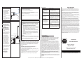
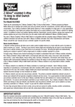
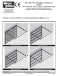
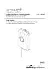
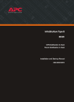
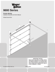
Package Contents:
1
1. Receiver
2. Antenna
3. Twin-lead wire, 6 feet
4. Manual
P.O. Box 67 Mt. Hope, OH 44660
(888) 827-3667
Optional Accessories:
Radio Receiver
Wiring:
1. Make sure door or gate
operator has been properly
installed in accordance with
unit’s installation instructions.
1. Disconnect power to the door
or gate operator before
proceeding.
2.
WARNING: Keep
fingers and other body
parts away from all
moving parts of the
door and gate
operators system
while the system is
being operated.
Models: 3990-372, 3994-433
Definition of Symbol
WARNING: To prevent
unintended operation,
disconnect power to
the door or gate
operator after
completing the above
preliminary operator
tests.
Warning
Installation Safety Precautions
WARNING: INCORRECT INSTALLATION CAN LEAD
TO SEVERE OR FATAL INJURY. FOLLOW THESE
INSTRUCTIONS CAREFULLY.
1.
Before installing this receiver, read the door or gate operator’s instruction
manual fully, so you are aware of all of the unit’s functions and features.
2.
Wear protective gloves to install, repair, or adjust door, gate, or operator
to avoid hand injuries.
3.
Wear eye protection when using tools to install, repair, or adjust door,
gate, or operator to prevent eye injuries.
Operating Temperature Range:.........................-22 F to 160 F
IP (Ingress Protection, International Protection):.... IP20
4.
NOTICE: Dry Locations Only
INPUT POWER
Non-polarized input connection.
10 to 28 VDC, 40 mA with relay off, 60 mA with relay active
10 to 28 VAC, 40 mA with relay off, 90 mA with relay active
5.
Before installing receiver, disconnect all power to door or gate operator
to prevent unintended operation.
6.
Do not connect this receiver to a power source until instructed to do so.
Do not reconnect power to the door or gate operator until instructed to
do so.
7.
Only install receiver on a properly functioning door or gate operator.
NOTICE: Class 2 product, for voltages 32 VAC/DC or less
RELAY OUTPUT CONTACTS
Normally-open, dry contacts, non-polarized connection.
Switching current capability:1.0 mA to 0.5 A at 10 to 28 VAC and 2.0 mA to
1.0 A at 10 to 28 VDC
RF Center Frequency:............................. Model 3990-372, 372.5 MHz.
Model 3994-433, 433.92 MHz.
Antenna length:....................................... Model 3990-372, 7.2 inch
Model 3994-433, 5.8 inch
Capable of learning 14 transmitters (any combination of portable
transmitters, RF wall-stations or RF keypads).
IMPORTANT NOTICE!
Read the enclosed instructions carefully before installing this radio receiver.
Pay close attention to all warnings and notes. This manual should be
retained for future reference.
© Copyright 2007 Wayne-Dalton Corp.
Part No.318705
Rev 3 7/9/2007
Mount control buttons within sight of door or gate, at a minimum height
of 5 ft, so small children cannot reach them. Keep control buttons away
from all moving parts of a door and at least 6 ft away from all moving
parts of a gate or its operator.
8.
Installation and wiring must comply with local building and electrical
codes. This product is not intended and must not be installed in a explosive environment.
9.
Pay close attention to all warnings, notices, and notes in these
instructions.
10. To prevent electrical shock and/or fire hazards, do not connect this
receiver to any voltages greater than 32 VAC or DC.
2. Connect the enclosed twin-lead
wires to the terminals labeled
RLY. (use only 22 AWG or larger;
CL2X or better)
3. Connect other end of twin-lead
wires to door or gate opener’s
control input.
4. Connect power to the two
terminals labeled PWR. Receiver
requires 10V to 28V AC or DC.
4
READ and FOLLOW all installation instructions.
Radio Receiver Specifications
PWR
WARNING: To prevent
electrical shock, be
sure electrical power is
disconnected before
proceeding with wiring.
2. Test and confirm proper
operation of the door or gate
operator before proceeding with
the installation of this receiver.
1.
1. Power Adapter
2. Antenna Extension Kit
Installation Instructions
and Owner’s Manual
3
Preliminary Operator Tests:
Connect Antenna:
2
Mounting:
WARNING: Do not
connect electrical
power to this receiver
until instructed to do
so.
WARNING: Disconnect
electric power to door
or gate operator before
making repairs or
removing case
covers.
1. Select a location four to six feet
from other receivers. Receiver
can be attached to metal, wood,
or plastic surfaces.
2. Use screws or other fastening
means to attach receiver.
3. If receiver is mounted inside a
metal enclosure, use an antenna
extension kit (optional) to extend
the antenna outside of the
enclosure.
WARNING: After installing and testing this receiver, test
all safety features of your door or gate’s operator.
Disconnect this receiver if any of your door or gate’s safety
system features fail to function properly. Then have your door
or gate operator serviced immediately by a qualified person.
You can reach us Toll Free 1-888-827-3667 for Consumer Assistance or online at www. wayne-dalton.com
Direct Connect Antenna: Attach
antenna as shown. For best
reception keep antenna wire
straight and away from metal
objects.
Antenna Extension Kit
(Optional):
1. Connect extension wire to
receiver.
2. Route wire outside metal
enclosure. Route and secure wire
away from moving parts.
3. Mount antenna holder outside
enclosure.
4. Screw antenna to extension
wire.
NOTICE: Do not route coax wire
near any moving parts of the
operator. If necessary, secure
coax wire away from any moving
parts.
5. Position antenna wire straight.
For best reception, keep antenna
away from metal.
NON-POLARIZED
PWR
RLY
RLY
Power
Supply
10V - 28V
AC/DC
Door or Gate
control input
5
LIMITED WARRANTY
Symptom
To Erase All Learned Transmitters:
If powered by Power Supply:
Plug power supply into source.
1. Press and hold down the PROGRAM button.
If powered by Operator:
Connect wires to the proper
operator accessory supply
source (10 V AC/DC to 28 V
AC/DC source).
2. After 10 seconds, the red STATUS LED will blink 5 times indicating
all transmitters are erased from the receiver’s memory.
4. Re-learn transmitters as needed following the above Programming
instructions.
2. Using wall control, activate
door or gate operator to confirm
power connection.
7
6
Safe Operation Precautions
Programming:
1.
2.
3.
WARNING: During
programming, door or
gate operator will activate. Keep people and
objects away from door
or gate.
1. Test receiver by operating a
compatible RF transmitter. The
Receiver’s STATUS LED will
flash indicating reception.
2. Press and release the
receiver’s PROGRAM button
once. The receiver’s red
STATUS LED will turn on and
remain on for 25 seconds,
indicating that the receiver is
ready to learn a transmitter.
3. Press the button on the
transmitter you wish to use to
control the operator. The
receiver’s red STATUS LED
will turn on and off three times
indicating a successful learn.
4. Press the same button on the
transmitter once more to confirm
operation of the door or gate
operator.
5. Test range of transmitter.
Repositioning antenna may
provide greater range.
6. Repeat Transmitter
Programming steps for
additional transmitters.
Check power source to receiver. Insure
proper 10 VAC/DC minimum to 28 VAC/
DC maximum power source.
2. No transmitter range
(less than 10 ft).
Check antenna connections and, if installed, check antenna extension kit coax
wire for damage or kinks. Correct antenna
connection or replace coax as needed.
3. Poor transmitter range
(less than 50 ft).
Insure antenna is not near any metal. Reposition antenna from vertical to horizontal
position or vice versa. Possible near-by
radio interference.
4. With transmitter
activation, the receiver’s
STATUS LED lights and
a ”click” is heard within
receiver, but receiver does
not activate operator.
Check relay (RLY) wire connections. Insure relay wire is not broken or damaged.
Insure relay wire is connected to proper
terminals on operator. Using insulated
pliers or insulated screwdriver, short RLY
terminals on receiver and this should
activate operator. Test operator for proper
operation.
WARNING: To reduce the risk of severe or fatal injury.
WARNING: Keep away
from all high-voltage
contacts while servicing
receivers.
4.
5.
6.
PROGRAM BUTTON
RED STATUS LED
7.
Always keep a moving door or gate in sight and keep people and
objects away until it is completely opened or closed.
No one should cross the path of a moving door or gate.
Never let children operate or play with the controls. Keep all controls
away from children.
Never go under a stopped, partially open door. Never walk through a
vehicular entry gate; always use the pedestrian entry.
Keep fingers and other body parts away from the all moving parts
of the door, gate and operator system while the system is being
operated.
Periodically test the safety systems of the door or gate. Disconnect
and do not use this receiver if any of your door or gate’s safety
systems fail their tests. Then have door or gate operator serviced
immediately.
Possible Solution
1. Receiver’s red STATUS
LED does not turn on
when programming button
pressed.
3. Release the PROGRAM button.
1. Re-connect power to the door
or gate operator.
RADIO RECEIVER
Trouble-Shooting:
6 (continued)
Connect Power Source:
5. Can not learn transmitter.
Insure transmitter is a correct transmitter
for this receiver. Check this receiver’s RF
frequency and the companion transmitter’s
frequency to insure they are identical. Test
receiver with another transmitter.
THE MANUFACTURER (WAYNE-DALTON CORP.) WARRANTS ALL COMPONENTS OF THE
RADIO RECEIVER MODEL 3990-372, 3994-433 FOR A PERIOD OF 90 DAYS FROM THE TIME
OF INSTALLATION AGAINST DEFECTS IN MATERIALS AND WORKMANSHIP, PROVIDED IT
IS PROPERLY INSTALLED, USED, MAINTAINED AND SERVICED UNDER NORMAL USE AND
SERVICE.
THE ABOVE CONDITIONS APPLY PROVIDED THAT THE ABOVE REFERENCED RADIO
RECEIVER MODEL 3990-372, 3994-433 IS PROPERLY INSTALLED, USED, MAINTAINED, AND
SERVICED IN ACCORDANCE WITH THE MANUFACTURER’S INSTALLATION AND OPERATING
INSTRUCTIONS UNDER NORMAL USE AND SERVICE.
THIS LIMITED WARRANTY EXTENDS ONLY TO THE ORIGINAL PURCHASER, PROVIDED THE
ABOVE REFERENCED RADIO RECEIVER IS PROPERLY INSTALLED, USED, MAINTAINED, AND
SERVICED. THIS LIMITED WARRANTY IS NOT TRANSFERABLE.
NO EMPLOYEE, DISTRIBUTOR, OR REPRESENTATIVE IS AUTHORIZED TO CHANGE THE
FOREGOING WARRANTIES IN ANY WAY OR GRANT ANY OTHER WARRANTY ON BEHALF OF
MANUFACTURER.
THE MANUFACTURER SHALL NOT BE RESPONSIBLE FOR ANY DAMAGE RESULTING TO
OR CAUSED BY ITS PRODUCTS BY REASON OF INSTALLATION, IMPROPER STORAGE,
UNAUTHORIZED SERVICE, ALTERATION OF PRODUCTS, NEGLECT OR ABUSE, ANY ACTS
OF NATURE BEYOND MANUFACTURER’S CONTROL (SUCH AS, BUT NOT LIMITED TO, LIGHTNING, POWER SURGES, WATER DAMAGE, ETC.), OR ATTEMPT TO USE THE PRODUCTS FOR
OTHER THAN THE CUSTOMARY USAGE OR FOR THEIR INTENDED PURPOSES. THE ABOVE
WARRANTY DOES NOT COVER NORMAL WEAR OR ANY DAMAGE BEYOND MANUFACTURER’S CONTROL OR REPLACEMENT LABOR.
CLAIMS FOR DEFECTS IN MATERIAL AND WORKMANSHIP COVERED BY THIS WARRANTY
SHALL BE MADE IN WRITING, WITHIN THE WARRANTY PERIOD, TO THE DEALER TO WHOM
THE PRODUCT WAS PURCHASED. MANUFACTURER MAY EITHER SEND A SERVICE REPRESENTATIVE OR HAVE THE PRODUCT RETURNED TO THE MANUFACTURER AT BUYER’S EXPENSE FOR INSPECTION. IF JUDGED BY MANUFACTURER TO BE DEFECTIVE IN MATERIAL
OR WORKMANSHIP, THE PRODUCT WILL BE REPLACED OR REPAIRED AT THE OPTION OF
THE MANUFACTURER, FREE FROM ALL CHARGES EXCEPT AUTHORIZED TRANSPORTATION
AND REPLACMENT LABOR.
THE REMEDIES OF BUYER SET FORTH HEREIN ARE EXCLUSIVE AND ARE IN LIEU OF ALL
OTHER REMEDIES, THE LIABILITY OF MANUFACTURER, WHETHER IN CONTACT, TORT,
UNDER ANY WARRANTY OR OTHERWISE, SHALL NOT EXTEND BEYOND ITS OBLIGATION TO
REPAIR OR REPLACE, AT ITS OPTION, ANY PRODUCT OR PART FOUND BY MANUFACTURER
TO BE DEFECTIVE IN MATERIAL OR WORK. MANUFACTURER SHALL NOT BE RESPONSIBLE
FOR ANY DIRECT, INDIRECT, SPECIAL OR CONSEQUENTIAL DAMAGES OF ANY NATURE.
THIS WARRANTY GIVES YOU SPECIFIC LEGAL RIGHTS, AND YOU MAY HAVE OTHER RIGHTS,
WHICH MAY VARY FROM STATE TO STATE. HOWEVER, SOME STATES DO NOT ALLOW LIMITATION ON HOW LONG AN IMPLIED WARRANTY LASTS OR THE EXCLUSION OR LIMITATION
OF INCIDENTAL OR CONSEQUENTIAL DAMAGES SO THE ABOVE LIMITATIONS OR EXCLUSIONS MAY NOT APPLY TO YOU.
SAVE THESE INSTRUCTIONS.
Operation:
Whenever this receiver senses a valid signal from a learned transmitter,
the relay will activate for one second and, therefore, activate the operator.
1. Press and release selected button on Wayne Dalton transmitter.
2. Receiver LED will light and the unit will cycle.
Maintenance:
Disconnect electric power to door or gate operator before making repairs
or removing case covers. While this receiver is maintenance-free, periodic
cleaning of the receiver case is suggested. To clean the receiver case,
disconnect power to receiver and operator and then use a soft cloth to
remove any dirt and dust.
Service:
Unit contains no user serviceable parts. Contact your dealer or
Wayne-Dalton customer support for additional information.
To Remove This Receiver From Service:
1. Disconnect power to operator (door operator, gate operator, etc.) and
disconnect power to this receiver.
2. Disconnect all wiring connected to receiver. Disconnect antenna and any
associated coax wiring.
3. Remove receiver from mounting location. Discard properly per local
codes.
4. Reconnect power to operator. Test operator for proper operation.
FCC and IC Statement
FCC Regulatory Information:
This device complies with Part 15 of the FCC Rules. Operation is subject
to the following two conditions: (1) this device may not cause harmful
interference, and (2) this device must accept any interference received,
including interference that may cause undesired operation.
IC Regulatory Information:
Operation is subject to the following two conditions: (1) this device may
not cause interference, and (2) this device must accept any interference,
including interference that may cause undesired operation of the device.
NOTE: This equipment has been tested and found to comply with limits for
a Class B digital device, pursuant to Part 15 of FCC Rules. These limits are
designed to provide reasonable protection against harmful interference in a
residential installation. This equipment generates, uses and can radiate radio
frequency energy and, if not installed and used in accordance with these
instructions, may cause harmful interference to radio communication; however,
there is no guarantee that interference will not occur in a particular installation. If this equipment does cause harmful interference to radio or television
reception, which can be determined by turning equipment off and on, user
is encouraged to try to correct interference by one or more of the following
measures:
Reorient or relocate receiving antenna. Increase separation between
equipment and receiver. Connect equipment into an outlet on a circuit different
from that which receiver is connected. Consult your dealer or/and experienced
radio/television technician for help.
WARNING: Changes or modifications to this unit not expressly approved by
party responsible for compliance could void user’s authority to operate this
equipment.
You can reach us Toll Free 1-888-827-3667 for Consumer Assistance or online at www. wayne-dalton.com
Questions?
STOP
Need Information?
Call Us Toll-Free:
(888) 827-3667
Thank you for your purchase
www.waynedalton.com
Please Do Not Return This Product To The Store
Call Us Directly! Our Trained Technicians Will Answer Your
Questions and /or Ship Any Parts You May Need.