1
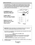
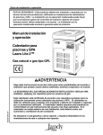
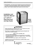
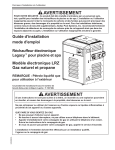
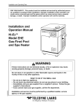
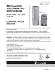
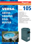
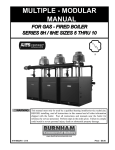
Installation and Operation Data FOR YOUR SAFETY - This product must be installed and serviced by a professional service technician, qualified in pool heater installation. Improper installation and/or operation could create carbon monoxide gas in flue gases which could cause serious injury, property damage, or death. Improper installation and/or operation will void the warranty. Installation and Operation Manual Laars Lite 2 Pool and Spa Heater Models LG and LD Natural Gas or LP Gas NOTE: LD LP Gas For Outdoor Use Only WARNING: If these instructions are not followed exactly, a fire or explosion may result, causing property damage, personal injury, or death. Do not store or use gasoline or other flammable vapors and liquids in the vicinity of this or any other appliance. H0235900- WHAT TO DO IF YOU SMELL GAS Do not try to light any appliance. Do not touch any electrical switch; do not use any phone in your building. Immediately call your gas supplier from a nearby phone. Follow the gas suppliers instructions. If you cannot reach your gas supplier, call the fire department. Installation and service must be performed by a qualified installer, service agency, or the gas supplier. TABLE OF CONTENTS SECTION 1. General Information 2G4a 2G-5. 2G-6. 2G-7. 2G-8. 2G-9. SECTION 2. Installation Instructions SECTION 3. Operating Instructions 1A. 1B. 1C. 1D. 2A. 2B. 2C. 2C-1. 2C-2. 2C-3. 2C-4. 2D. 2E. 2E-1. 2E-2. 2F. 2F-1. 2F-2. 2F-3. 2G. 2G-1. 2G-2. 2G-3. 2G-4. Introduction ................................................... 1 Description ................................................... 2 Warranty ....................................................... 2 Technical Assistance .................................... 2 General Information ..................................... 2 Field Assembly ............................................. 2 Site Location ................................................ 3 Installation Information ................................. 3 Outdoor Installation ...................................... 4 Flooring - Typical Installation ....................... 4 Indoor and Outdoor Shelter Installation ........ 4 Combustion and Ventilation Air Supply ........ 5 Gas Supply and Piping ................................. 5 General Instructions ..................................... 5 Special Precautions for Propane Gas .......... 6 Electrical Wiring ........................................... 6 General Information (LD Only) ..................... 6 Auxiliary Time Clock Wiring ......................... 8 Remote Operation (Model LD Only) ............. 9 Water Flow System ...................................... 9 Flange Installation ........................................ 9 Reversible Water Connections ................... 10 Valve Installation ........................................ 12 Chlorinators, Ozone Generators, and Sanitizing Chemicals .................................. 12 3A. 3B. 3B-1. 3B-2. 3C. 3D. 3D-1. 3D-2. 3D-3. 3E. 3F. 3G. 3H. 3H-1. 3H-2. Water Chemistry ........................................ 13 Pressure Relief Valve ................................. 13 Adjusting the Pressure Switch .................... 13 Automatic Flow Control Valve .................... 14 Temperature Rise ....................................... 14 Adjusting the Manual Bypass Valve ........... 15 General Information ................................... 16 Lighting and Shutdown Procedures ............ 16 Model LD (Direct Ignition) .......................... 16 Model LG (Standing Pilot) .......................... 16 Setting the Temperature Control ................ 16 Seasonal Care ............................................ 19 Spring and Fall Operation .......................... 19 Winterizing ................................................. 19 Spring Startup ............................................ 19 Water Chemistry ........................................ 20 Spa/Hot Tub Safety Rules .......................... 20 Swimming Pool Energy Saving Tips .......... 20 Periodic Inspection ..................................... 21 Owner Inspection ........................................ 21 Professional Inspection .............................. 21 SECTION 4. Parts List for Laars Lite 2 Heater 4A. 4B. General Information .................................. 21 Parts List ................................................... 21 Model LG & LD Pool and Spa Heater Page 1 SECTION 1. General Information with the installation. Consult the Waterpik Laars factory, or local factory representative, with any questions regarding this equipment. Experience has shown that most operating problems are caused by improper installation. The Laars Lite 2 heater is design certified by International Approval Services (formerly American Gas Association and Canadian Gas Association) as complying with the latest edition of the Standard for 1A. Introduction This manual provides installation and operation instructions for the Laars Lite 2, Model LG and LD pool and spa heaters. Read these installation and operation instructions completely before proceeding (920 cm) Venting Dimensions Model Heater Size Width Vent Diameter U.S. Outdoor Dim "H" U.S. Indoor or Firing Rate / Hr. CAN Outdoor Shelter Dim "H" (1,000's) in (cm) in (cm) in (cm) in (cm) BTU (kcal) 125 15 (38) 5 (12.7) 9 1/8 (23) 16 1/4 (41.3) 125 (31.5) 175 18 (45.7) 6 (15.2) 9 3/4 (24) 24 1/8 (61.3) 175 (44.1) 250 22 1/2 (57.2) 7 (17.8) 10 (26) 25 1/4 (64.1) 250 (63) 325 26 3/4 (67.9) 8 (20.3) 10 5/8 (27) 26 1/2 (67.3) 325 (81.9) 400 31 3/4 (80.6) 9 (22.9) 13 1/4 (34) 27 1/2 (69.9) 400 (101) Notes: 1. In Canada, derate BTU/Hr input and output 10 percent for altitudes of 2,000 to 4,500 feet (609 to 1372 m) above sea level. No derating necessary up to altitude of 2,000 feet (609 m). In United States derate input 4 percent for each 1,000 feet (305 m) above sea level, starting at 2,000 feet (609m). 2. The Laars Lite 2 is constructed for 75 psi working pressure. 3. Ratings shown are for both natural and propane gas. Figure 1. General Configuration. Page 2 Gas-Fired Pool Heaters, ANSI Z21.56, and in Canada with CAN1-4.7-M85. Certain sections of this manual are specific to either United States or Canadian installations, and are labeled as such. 1B. Description The Laars Lite 2 LD heater gets electrical power from an external 120VAC or 240VAC source and provides a dual thermostat Flex-Temp control system for pool/spa combinations or preheat convenience. The Laars Lite 2 LD heater also meets the California, New York, Hawaii, and Oregon state energy requirements for intermittent ignition gas appliances. The Laars Lite 2 LG heater is a self contained standing pilot unit and requires no external power. The Laars Lite 2 heater is specifically designed for heating swimming pools and spas. Do not use it as a general service water heater. There is a specially designed model of Laars Lite 2 for heating salt water pools. Consult your dealer for the appropriate Waterpik Laars products for these applications. 1C. Warranty The Laars Lite 2 heater is sold with a limited factory warranty. Details are specified on the back cover of this manual. A copy of the warranty and a warranty registration card are included in the plastic bag shipped with the heater. Fill out and return the warranty registration card. Make all warranty claims to an authorized Waterpik Laars representative or directly to the factory. Claims must include the heater serial number and model (this information can be found on the rating plate), installation date, and name of the installer. Shipping costs are not included in the warranty coverage. Damage caused by improper installation or assembly, or to the heat exchanger by corrosive water, is NOT covered by the Warranty. See Section 3D for maintaining proper pool water chemistry. NOTE: Keep this manual in a safe place for future reference when inspecting or servicing the heater. 1D. Technical Assistance Consult Waterpik Laars or your local distributor with any questions or problems involving the specifications, installation, and operation of your Waterpik Laars equipment. An experienced technical support staff is ready to assist in assuring the proper performance and application of Waterpik Laars products. For technical support call (415) 382-8220 extension 260. WATERPIK TECHNOLOGIES INC. SECTION 2. Installation Instructions 2A. General Information Install the Laars Lite 2 heaters, vent caps and drafthoods in accordance with the procedures in this manual, local codes and ordinances, and in accordance with the latest edition of the National Fuel Gas Code, ANSI Z223.1. In Canada, the installation must be in accordance with CAN1-B149.1 or .2 and local codes. The authority having jurisdiction may require that the installation conform to the Standard for Gas-Fired Heaters, ANSI Z21.56. Any changes to the heater, gas controls, gas orifices, wiring, draft diverter, or improper installation may void the warranty. If field conditions require change to any of the above, consult the factory. All gas-fired products require correct installation to assure safe operation. The requirements for pool heaters include the following: 1. Field assembly (if required) 2. Appropriate site location (clearances) and flooring 3. Sufficient combustion and ventilation air 4. Properly sized gas meter and piping 5. Proper electrical wiring (if required) 6. Adequate water flow This manual provides the information needed to meet these requirements. Review all application and installation procedures completely before continuing the installation. 2B. Field Assembly The Laars Lite 2 heater is shipped from the factory with the top assembly in the low-profile configuration for outdoor installation in the U.S. In Canada, an outdoor installation requires the addition of a factory approved vent cap. The Laars Lite 2 heater is design certified for indoor installation when equipped with a drafthood, which must be installed without modification. The Laars Lite 2 heater is also certified for installation in an outdoor shelter in Canada when equipped with a drafthood. An outdoor shelter is an enclosure not normally occupied which does not communicate directly with occupied areas. Check the rating plate on the heater or the Parts List (Sec. 4) of this manual for the correct Waterpik Laars drafthood or vent cap part number. See instructions supplied with the drafthood or vent cap for installation and attachment. When the drafthood is used, locate the heater so as to be in the same atmospheric pressure zone as the combustion air inlet to the heater. Model LG & LD Pool and Spa Heater Page 3 Notes: 1. An Underwriters' Laboratories listed vent cap is required to prevent downdraft and allow the heater to function properly and safely. 2. Use approved roof jack. Figure 2. Indoor Installation Venting (USA), or Outdoor Shelter (Canada). Table 1. Air Openings to Outside. 2C. Site Location Required Net Free Open Area for Combustion Air Openings Model 125 175 250 325 400 Direct from outside in2 (cm2) 32 (206) 44 (284) 63 (406) 82 (429) 100 (645) WARNING Improper installation or maintenance can cause nausea or asphyxiation from carbon monoxide in flue gases which could result in severe injury, or death. Duct from outside in2 (cm2) 64 (413) 88 (568) 126 (813) 164 (1058) 200 (1290) 2C-1. Installation Information Avoid placing the heater in locations where it can cause damage by water or condensate leakage. If this is not possible, provide a suitable drain pan to catch and divert any leakage. The pan must not block natural flow of air around the heater. Locate the heater so the clearances from combustible surfaces shown in Table 2 are met. Note: If using screens and/or louvers, compensate by adding 50% additional area to each opening. When a drafthood is used, it must be connected to a vent pipe which stops at least 2 feet (0.61 meters [m]) above the highest point of the roof or other object that is within 10 feet (3.05 m) from the vent termination. The vent pipe must have a listed vent cap which allows a full equivalent opening for flue products (see Figure 2). Table 2. Minimum Heater Clearances From Combustible Surfaces Indoor (Outdoor Shelter) Installation U.S. Outdoors Installation Canada U.S. Canada inch ( cm ) inch ( cm ) inch (cm ) inch (cm ) Blank 6 ( 15.2 ) 6 ( 15.2 ) 6 ( 32 ) 6 (15.2 ) Rear 6 ( 15.2 ) 6 ( 15.2 ) 6 ( 32 ) 6 (15.2 ) Piping 12 ( 30.5 ) 18 ( 45.7 ) 12 (30.5 ) 18 (45.7 ) Top 44 (111.7 ) 44 (111.7 ) Front 18 ( 45.7 ) 36 ( 91.4 ) Side of Heater Open Unroofed Area 18 ( 45.7 ) 36 ( 91.4 ) Page 4 2C-2. Outdoor Installation Laars Lite 2 heaters can be installed in the lowprofile, grate top configuration (U.S.A. only) as received from the factory, or with an optional high wind vent cap/stack. Canadian units require a factory approved vent cap. WATERPIK TECHNOLOGIES INC. feet (0.91 m) from vertical surfaces (e.g., nearby buildings and walls). The addition of a vent cap may be necessary. 2C-3. Flooring - Typical Installation Do not install the heater directly on a combustible wood or carpet floor without placing a noncombustible platform between the floor and the heater. In the United States, the National Fuel Gas Code allows a heater to be placed on a combustible surface when there is a platform under the heater made of hollow masonry no less than 4 inches (102 millimeters [mm]) Figure 3. Outdoor Heater Installation. Locate the heater in an open, unroofed area. Do not install the heater under a deck. Do not locate the heater below or adjacent to any doors, glass openings, louvers, grills, etc., which connect in any way with an inhabited area of a building, even though the access might be through another structure (e.g., a garage or utility room. In the United States there must be a minimum of 4 feet (1.22 m) horizontally or vertically between the heater and any door, glass opening, or gravity inlet to a building. In Canada this distance must be at least 10 feet (3.0 m) (see Figure 3). WARNING United States Do not install the heater with the top of the vent assembly within 4 feet (1.22 m) of any opening into a building. Canada Do not install the heater with the top of the vent assembly within 10 feet (3.05 m) of any opening into a building. If the heater is installed under an overhang, there must be a minimum clearance of 5 feet (1.5 m) above the top of the heater and the structure should not overhang the heater more than 12 inches (0.30 m). The area under the overhang must be open on three sides. This prevents combustion gases from being diverted into living areas through doors, windows, or gravity inlets. If the heater is installed close to a structure, protect it from rain water runoff with rain gutters on the roof or other measures. Do not locate the heater near sprinkler systems that could spray water on it. Avoid locations where wind deflection off nearby structures might cause downdraft conditions. Where downdraft conditions exist, locate the heater at least 3 Notes: 1. Blocks must provide solid base and be braced so they cannot slip out of place. 2. Air openings in blocks must be arranged to provide unrestricted opening through entire width or length of base. Figure 4. Non-Combustible Platform. thick, covered with sheet metal at least 24 gauge thick and extending beyond the full width and depth of the heater by at least 6 inches (76.2 mm) in all directions. The masonry must be laid with ends unsealed, and joints matched to provide free circulation of air from side to side through the masonry (see Figure 4). If the heater is installed in a carpeted alcove, the entire floor of the alcove must be covered by a noncombustible panel. You can obtain a noncombustible base from Waterpik Laars, see the Parts List (Sec. 4) of this manual. 2C-4. Indoor and Outdoor Shelter Installations All indoor installations and outdoor shelter installations (Canada) require the addition of a factory approved drafthood. The drafthood must be installed Model LG & LD Pool and Spa Heater Page 5 without modification and in accordance with all local, state, provincial and national codes. Proper ventilation of exhaust and combustion air are essential for the safe operation of the heater. Manual Shutoff Valve 2D. Combustion and Ventilation Air Supply All indoor installations must have openings to outside air for combustion, ventilation, and dilution of flue gases from inside the building (see Figure 2 and Table 1). Waterpik Laars does not recommend indoor installations that do not provide combustion air from outside the building. All outdoor shelter installations (Canada only) must have uninterrupted openings to outside air for combustion and ventilation. The installation must be in accordance with the latest edition of CAN/CGA B149. Waterpik Laars does not recommend outdoor shelter installations that depend on internal air for combustion. Combustion air should be ducted to the heater from outside the structure. If the heater is installed in a residential garage, or where flammable vapors will be present, the burners must be 18 inches (457 mm) above the garage floor. Refer to the latest edition of the National Fuel Gas Code for more information. In Canada, refer to the latest edition of the Gas Installation Code, CAN/CGA B149. Gas Supply Inlet T-Fitting 3" Min. (76 mm) WARNING Do not convert this heater from natural gas to propane gas, or propane to natural. Field conversion could create carbon monoxide gas which can cause property damage, serious injury, or death. 1. Gas piping installation must be in accordance with the latest edition of ANSI Z223.1 and all local codes. In Canada, the installation must be in accordance with CAN- B149.1 or .2 and all local codes that apply. 2. Check the rating plate to make sure the heater is fitted for the type of gas being used. Waterpik Laars heaters, as shipped from the factory, are certified to operate at an altitude of 0 to 3000 feet (0 to 915 m) for natural gas and 0 to 5000 feet (0 to 1525 m) for propane gas in the United States. Or if so ordered, at higher altitudes. For higher altitudes, the heater manifold is marked with a tag or sticker indicating one of the following high altitude operation codes: Nipple To Equipment Inlet Cap Figure 5. The proper design for a sediment trap / drip leg. a. High altitude (H) - 3,000 to 6,000 feet (915 to 1,830 m) for natural gas and 5000 to 10,000 feet (1525 to 3050 m ) for propane gas. b. High altitude (J) - 6,000 to 10,000 feet (1830 to 3,050 m) 3. In Canada, the heater rating plate is marked for specific altitude requirements: lo altitude is 0 to 2,000 feet (0 to 610 m) and high altitude (H) is 2,000 to 4,500 feet (610 to 1,370 m) above sea level for natural gas and 0 to 4500 feet (0 to 1370 m) for propane gas. 4. Use the figures in Table 3 to size the gas inlet piping from the gas meter to the heater. Check all local codes for compliance before installing the heater. 2E. Gas Supply and Piping 2E-1. General Instructions Review the following general instructions before continuing the installation. Union Table 3. Natural Gas Pipe Size Requirements Distance from Gas Meter 0-50 feet 50-100 feet Heater (0-15 m) (15-30 m) Size in. (mm) in. (mm) 125 3/4 (19) 1 (25.4) 175 1 (25.4) 1 (25.4) 250 1 (25.4) 1-1/4 (31.75) 325 1-1/4 (31.75) 1-1/4 (31.75) 400 1-1/4 (31.75) 1-1/2 (38) 100-200 feet (30-60 m) in. (mm) 1 (25.4) 1-1/4 (31.75) 1-1/4 (31.75) 1-1/2 (38) 1-1/2 (38) Notes: 1. These numbers are for natural gas (0.65 Sp. Gr.) and are based on 1/2 inch (13 mm) water column pressure drop. Check supply pressure with a manometer, and local code requirements for variations. For liquefied petroleum gas, reduce pipe diameter one size, but maintain a 3/4 inch (13 mm) minimum diameter. 2. Check supply pressure and local code requirements before proceeding with work. 3. Pipe fittings must be considered when determining gas pipe sizing. WATERPIK TECHNOLOGIES INC. Page 6 Table 4. Gas Supply Pressure Requirements Supply Pressure Water Column Minimum Maximum Natural Gas in. (mm) 5.5 (140) 10.0 (254) Propane Gas in. (mm) 10.0 14.0 Install a sediment trap (drip leg) ahead of the gas controls (see Figure 5). Fit the trap with a threaded cap which can be removed for cleaning. 6. Install a manual gas shutoff valve for service and safety. Do not use a restrictive gas cock. DO NOT USE FLEXIBLE GAS PIPING. 7. Disconnect the heater and its individual shutoff valve from the gas supply system during pressure testing of the system at pressures higher than 1/2 pounds per square inch (psi) (3.45 kilopascals [kPa]). If the test pressure is equal to or less than 1/2 psi (3.45 kPa), close the manual shutoff valve on the heater during the piping pressure test. Caution Permanent damage to the gas valve will occur if the following procedures are not followed. If the gas supply pressure is less than required, check for undersized pipe between the meter and the heater, a restrictive fitting, or an undersized gas meter. Gas supply pressures to the heater are listed in Table 4. NOTE: The maximum inlet gas pressure must not exceed the specified value. The minimum value listed is for the purpose of input adjustment. Refer to Table 4. 9. Caution Label all wires prior to disconnection when servicing controls. Wiring errors can cause improper and dangerous operation. Verify proper operation after servicing. (254) (356) 5. 8. 2F. Electrical Wiring Before operating the heater, test the complete gas supply system and all connections for leaks using a soap solution. Do not use an open flame. Attention Au moment de l'entretien des commandes, étiquetez tous les fils avant de les débrancher. Des erreurs de câblage peuvent entraîner un fonctionnement inadéquat et dangereux. 2F-1. General Information (LD Only) Wiring connections must be made exactly as shown in the wiring diagram found on the inside of the heater (see Figures 6 and 7 for typical examples) . The heater must include a definite means of grounding. There is a bonding lug on the right side of the heater, where a bond wire must be attached. The heater comes factory-wired intended for use with 240 Volt, 60 Hz AC field electrical supply. To use 120 Volt, 60 Hz AC requires rewiring of the heater. This should be done by a certified electrician only, as with all wiring. To wire the heater for 120 Volt, 60 Hz AC, follow the alternate 120V wiring method depicted in Figure 6. Additionally, the ignition control module must be rewired. The wire from the terminal marked IGN/240 must be removed from that terminal and placed on the terminal marked IGN/120. Electrical wiring must be in accordance with the latest edition of the National Electric Code (NEC), ANSI/National Fire Protection Association (NFPA) 70, unless local code requirements indicate otherwise. To wire the Laars Lite 2 model LD heater to a 120V or 240V /60 Hertz (Hz) electrical source: 1. Remove the screw located to the lower right side of the transformer and open the hinged cover of the wiring enclosure. Caution Some leak test solutions (including soap and water) may cause corrosion or stress cracking. Rinse the piping with water after testing. 2. Connect the wires from the power source to the leads on the right side of the heater in the space behind the ignition control (see Figure 8). Be sure to follow the wiring diagram on page 7 to configure the transformer for the correct input voltage. 2E-2. Special Precautions for Propane Gas Liquefied petroleum (LP) gas is heavier than air. Therefore, do not install pool heaters using LP gas in pits or locations where gas might collect. Locate heaters a safe distance from LP gas storage and filling equipment. Consult local codes and fire protection authorities about specific installation restrictions. 3. Attach the ground wire to the green ground screw located on the back panel of the wiring enclosure. 4. Close the cover of the wiring enclosure and replace the screw to hold it in place. 5. Connect a bonding wire (8 ga copper) to the bonding lug on the right side of the heater. NOTE: No external junction box is required. Model LG & LD Pool and Spa Heater Page 7 MODEL LD WIRING DIAGRAM HSI IGNITION WIRE FACTORY WIRED - 120 V/240 V FIELD WIRED - 120V /240V FACTORY WIRED - 24 V OFF POOL SPA REMOTE CONNECTOR FIREMAN SWITCH FUSIBLE CONNECTION LIMIT W LINK W BK LIMIT W W NOTE: IF ORIGINAL WIRE SUPPLIED WITH HEATER MUST BE REPLACED, APPLIANCE WIRING O MATERIAL RATED AT 105 C SHALL BE USED. WIRING SHOWN AS SHALL USE APPLIANCE WIRING MATERIAL RATED AT 200 OC. ELEC. FUSE TRANSFORMER 120-240 V R BK BK W/R WATER TEMP SENSOR G/Y PRESSURE SWITCH Y/BK W HONEYWELL GAS VALVE W BR MV2 ATTACH GROUND WIRE HERE R BK W/R FLAME SENSE ROD W R G IGNITION CONTROL (FENWAL) 0533 ALTERNATE 120 V WIRING TRANSFORMER 120-240V / 24 V BK GND Y R WIRE TO IGN/120 FOR 120 VOLTS WIRE TO IGN/240 FOR 240 VOLTS BK IGN/120 IGN/240 (LI) (L2) IGN FS TH VALVE W MV1 W/BK Y W/BK R R Y G IGNITER a) Connection Diagram BK (L1) (L2) ONLY 120 V 240V CONNECTION SHOWN 60 HZ L1 PRESSURE 150 F SWITCH HI-LIMIT SWITCH O 135 F HI-LIMIT SWITCH FUSIBLE LINK FIREMAN SWITCH CONNECTOR SPA SET POINT R ATTACH GROUND WIRE HERE L2 Y R O 240V 60 Hz SINGLE PHASE BK W BR Y R O Y/BK W/BK W/R G/Y - TRANSFORMER ELECTRICAL 24 V FUSE 1-25 AMP POOL SET POINT Black White Brown Yellow Red Orange Yellow & Black White & Black White & Red Green & Yellow OFF BK CIRCUIT SEN BK/Y SEN GND W TH W WATER TEMPERATURE SENSOR FS VALVE GND L2 IGN L1 IGN120 or IGN240 W IGNITION CONTROL W H/W GAS VALVE BR MV1 MV2 W b) Schematic Diagram Figure 6. LD Connection/Schematic Wiring Diagram. Y IGNITOR FLAME SENSOR H0236300- WATERPIK TECHNOLOGIES INC. Page 8 efficient operation by removing any residual heat contained in the heat exchanger back to the pool. 2F-2. Auxiliary Time Clock Wiring (LD) If you install a time clock to control the filter pump operation, it is recommended that the time clock have its own low voltage (Firemans) switch to turn off the heater before turning off the pump. The switch should shut off the heater about 15 minutes before the filter pump shuts off. This will allow for a more Caution Do not provide power to the heater from the high voltage side of the time clock. Doing so may cause damage to the heater or surrounding plumbing. 0,//,92/7+($7(5:,5,1*',$*5$0 BK W Y R O - High Limit Switch High Limit Switch Connection Diagram Black White Yellow Red Orange TEMP. CONTROL On Off O W W Fireman Switch Connection BK Fusible Link W W Y O BK Y Y Max BK W Y Min Y Pressure Switch TH BK PP/TH W Y PP Pilot Gen R Piezo Sparker W Pilot IF ANY OF THE ORIGINAL WIRE AS SUPPLIED WITH THE HEATER MUST BE REPLACED, APPLI ANCE WIR ING MATERIAL RATED FOR 105°C MUST BE USED. WHERE MARKED THUS APPLIANCE WIRING MATERIAL FOR 200°C MUST BE USED. W Piezo Sparker _ R + To Pilot Generator PP Y Y PP/TH Pilotstat Power Unit Coil W TH/PP TH BK BK CIRCUIT PP Valve Operator Coil Y H0166000G Figure 7. LG Connection/Schematic Wiring Diagram Model LG & LD Pool and Spa Heater Figure 8. Field Wiring Connections (LD). Page 9 2F-3. Remote Operation (Model LD Only) The Laars Lite 2 pool/spa heater controls can be wired for remote operation. The CS-02 remote control permits switching from one temperature controller to the other and turning the heater on and off from a remote location. The CS-04 includes the same features as the CS-02 plus a remote temperature controller. Contact Waterpik Laars for further information. Reference part numbers CS-02 and CS-04. An interrupt (on/off) type remote can be connected by removing the jumper wire on the terminal block located in the control compartment (see Figure 6) and connecting the two wires from the remote to the two terminals on the terminal block. This type of remote control will turn the heater on or off, but will not switch between the two temperature controllers on the temperature control panel or allow for temperature adjustments. To connect a 3-wire remote (not supplied by Waterpik Laars) to a Laars Lite 2 LD heater, order a wire harness assembly (part No. E0120000) which connects to the temperature control panel. Installation instructions are included with the wire harness assembly. Consult with Waterpik Laars Service Department with questions about installing remotes other than Waterpik Laars. 2G. Water Flow System Figure 9. Time Clock Wiring. To install a time clock auxiliary switch into the heater wires (see Figure 9): 1. Remove heater door. 2. Remove the factory installed wire between terminals 1 and 2 on the terminal strip (see Figure 9). 3. Connect the wires from the time clock auxiliary switch to the two terminals. Use American Wire Gage (AWG) No. 14 gauge stranded copper wire with a temperature rating of 221°F (105°C) or greater. The length of the wire between the heater and the time clock should not exceed 10-15 feet (4.57 m). The contact points of the time clock switch should be silver, or a low resistance alloy. 2G-1. Flange Installation The heater has 2" NPT universal header couplings. You can connect threaded 2" NPT iron pipe, unthreaded 1-1/2" iron pipe, 1-1/2" or 2" copper pipe without an adapter (see Figure 10). Plastic piping (PVC Schedule 40) can be connected to the heater if local codes allow it, by using the CPVC nipples included with your heater. To install plastic piping (see Figure 11): 1. Remove CPVC nipples from plastic bag. 2. Screw CPVC nipples into metal flange until tight, using teflon tape on plastic threads. 3. Attach PVC plumbing to CPVC pipes using PVC to CPVC cement only. Page 10 WATERPIK TECHNOLOGIES INC. 2G-2. Reversible Water Connections Waterpik Laars ships the Laars Lite 2 heater with the water connections on the right side. The Laars Lite 2 heater can be installed with the water connections on either side. It could be necessary, or helpful, to switch the connections to the left side to improve access for installation and service. Perform this modification before installing the heater using the following procedures: REAR RAIN SHIELD PANEL OMITTED ON CANADIAN MODELS TRANSITION PLATE TOP OMITTED ON US MODELS Figure 10. Piping installation. RUBBER JACKET/PLUG GROMMET Figure 11. Plastic piping connections. Figure 12. Heat exchanger reversal. Model LG & LD Pool and Spa Heater Page 11 1. 2. Remove heater door. If there is a vent cap or drafthood (indoor) on top of the heater, remove it. 3. Remove all 8 hex-head screws fastening the top and lift the top assembly straight up (see Figure 12). 4. Remove rainshield assembly and set it aside. 5. Remove screws that fasten the gap closures to the jacket and put them aside. Remove gap closures. 6. Remove the screws securing the two flue collector hold down clamps and remove the clamps (see Figure 13). Remove flue collector. 7. Remove the three rubber jacket/plug grommets and drain plugs (see Figure 12). One is located under the water connections on the right side. The other two are on the left side toward the front of the heater. 8. Tag and disconnect the white wire on the pressure switch (PS) and the white wire on the Fireman's switch terminal (see Figure 6 or 7) which leads to the high limit switch. 9. Remove plastic tie wraps and pull the white wires out of the front compartment through the vestibule cover and coil them on the heat exchanger. 10. Unscrew the brass compression fitting securing the pressure switch to the inlet/outlet header. Remove tube from header and gently bend it out of the way. 11. Loosen the screw securing the temperature sensing bulb retainer bracket. Slide the retainer bracket off the bulb flange and remove the bulb from the header (see Figure 14). Pull pressure switch tube through the hole in the vestibule cover and into the vestibule (controls compartment), then pull thermostat bulb assembly through same hole (see Figure 15). 12. When removing the heat exchanger from the heater, the end baffles of the heat exchanger must be removed. There are two baffles covering part of the front and rear tubes of the heat exchanger. Each baffle is held in place by two screws which mount to the top of the combustion chamber wall. Remove the screws and the baffles before attempting to lift the heat exchanger out of the heater (see Figure 16). Caution It may be necessary to have help lifting the heat exchanger out and replacing it. Figure 14. Temperature sensing bulb. HOLD DOWN CLAMP IN/OUT HEADER (U.S. MODELS ONLY) LEFT VESTIBULE COVER RIGHT VESTIBULE COVER BRACKET Figure 13. Flue collector hold-down brackets. FRONT Figure 15. Vestibule covers. PLASTIC BUSHING WATERPIK TECHNOLOGIES INC. Page 12 20. Connect the white wire labeled PS to the pressure switch and the other white wire to its original location on the Fireman's switch. Heat Exchanger End Baffles Heat Exchanger Combustion Chamber Wall 21. Reinstall the drain plugs and tighten securely. Replace jacket/plug grommets. 22. Install the flue collector assembly. Be sure the front and rear panels of the flue collector are installed into the grooves on the front and rear combustion chamber heat shield panels. Be sure the sheet metal panels are not pinching any wires. 23. Attach the flue collector hold down clamps to the clips located under the two center header bolts. 24. Replace the gap closures and tighten the screws securely. Figure 16. Heat exchanger and end baffles. 13. Lift the heat exchanger assembly out of the heater. Reinstall heat exchanger 180 degrees (inlet/outlet header left) from it's original position. 14. After replacing the heat exchanger into the heater, the end baffles must be replaced. Each one is held in place by two screws which mount to the top of the combustion chamber wall. Reinstall the baffles on the front and rear of the heat exchanger before continuing with the "Reversible Water Connections" procedure. 15. Remove pressure switch retainer (plastic cable clamp) from the inner panel (allow pressure switch to float). 16. On U.S. models reroute pressure switch tube and thermostat bulb assembly through hole in left side of vestibule cover in reverse order. Canadian models have no cover on the left side of the vestibule. Relocate the pressure switch tube and temperature sensor through the open side of the vestibule. 17. Reinstall the temperature sensing bulb in the header, and fasten it with the retainer bracket and screw. 18. Reinstall the compression fitting at end of pressure switch tube into inlet/outlet header and tighten the fitting. 19. Route the white wiring from the high limit switches beside the heat exchanger and down to the original location following the pressure switch tubing. Secure white wires to the pressure switch tube with plastic wire ties. 25. Double-check to make sure the wiring is not pinched against sharp edges, or resting on the flue collector assembly. 26. Reinstall rainshield assembly. 27. Replace the top assembly. Make sure the tabs are outside the heater jacket. Fasten the top assembly with the hex-head screws. 28. Install plastic tie wraps on wiring in the vestibule (controls compartment). 29. Install heater door. 30. Reinstall the vent cap or drafthood, if one was removed. 2G-3. Check Valve Installation Install a check valve if there is any chance of backsiphoning when the pump stops. Do not install any other valve in the piping between the heater outlet and the pool, unless it is being used as a diverter valve. 2G-4. Chlorinators, Ozone Generators, and Sanitizing Chemicals The Waterpik Laars Lite 2 heater is manufactured with materials that are not compatible with high concentrations of ozone, chlorine, bromine, or other sanitizing chemicals. Heater damage caused by excessive chemicals or improper ozonization is not covered by the Waterpik Laars warranty. Be sure to adhere to the following: When ozone is injected upstream of the heater, install an offgas mixing chamber, or an ozone bypass system between the heater and the ozone injector to prevent ozone and air from entering the heater. Model LG & LD Pool and Spa Heater When chemical feeders are used, plumb the feeder downstream of the heater and install an inline check valve between the heater and the feeder (a minimum of 18" is required between the heater and the check valve). Never deposit chemicals directly in the pool skimmer. 2G-4a. Water Chemistry Proper chemical balances are necessary for sanitary bathing conditions as well as ensuring your heater's long life. Be sure to keep your chemical levels within the values indicated in Table 7. Waterpik Laars does not warrant heat exchangers damaged by corrosive chemical levels or excess dissolved solids in pool or spa water. For spas, it is also necessary to perform water changes in addition to chemical treatment. It is recommended to change the spa water every 60 days for light usage and every 30 days if usage is heavy. Table 7. Mineral Concentration Levels Test Recommended Level Free chlorine 1.0 to 3.0 ppm Bromine 3.0 to 5.0 ppm pH 7.2 to 7.8 Total alkalinity (TA) 80 to 120 ppm Calcium hardness (CH) 200 to 400 ppm Langelier saturation index (LSI) -0.5 to +0.5 Total dissolved solids (TDS) Less than 2000 ppm Cyanuric acid 30 to 150 ppm Copper 0 ppm 2G-5. Pressure Relief Valve A pressure relief valve is not furnished with the Laars Lite 2 heater. However, it is recommended that a pressure relief valve be installed and may even be required by local codes. To install a pressure relief valve, remove the 3/4 inch (19 mm) brass plug located on the top of the inlet/ outlet header (see Figure 17). Install the pressure relief valve in the threaded hole from which the plug was removed. The pressure rating of the valve should be at or below the lowest working pressure of any component in the filter system. Any pressure relief valve installed must comply with provisions of the Standard described in ANSI Z21.22 for the United States, or CAN1-4.6 in Canada. Page 13 Figure 17. Thermometer and pressure relief valve. 2G-6. Adjusting the Pressure Switch Caution The pressure switch should be adjusted to turn the heater off when the pump is off. Setting the switch to close at too low of a flow can damage the appliance. Adjust the switch to turn the heater off, not on. The pressure switch is preset at the factory for activation at 2 psi (14 kPa). Adjust the pressure switch only if any part of the filter system piping is 3 feet (0.91 m) or more above the top of the heater jacket. Do not adjust the pressure switch if the heater is installed more than 15 feet (4.57 m) below or 6 feet (1.83 m) above the pool surface. Consult your local Waterpik Laars representative for recommendations. On some installations, the piping from the heater to the pool is very short. The back pressure could be too low to trigger the pressure switch. If this happens, it may be necessary to install a directional fitting or elbows where the return line enters the pool. This will increase back pressure enough for the heater to operate properly. Make sure the pool filter is clean before making any pressure switch adjustment: A dirty filter will restrict the water flow and the pressure switch cannot be adjusted properly. To adjust the pressure switch: 1. Set the control panel rotary switch (LD) or the control panel rocker switch (LG) to the OFF position (see Figure 18). 2. Set the Pool temperature control to the Max position. 3. Turn filter pump on. If a two-speed pump is used, make sure it is at high speed. WATERPIK TECHNOLOGIES INC. Page 14 a) Model LD Temperature Control 2G-7. Automatic Flow Control Valve The automatic flow control valve maintains the proper flow through the heater at rates up to approximately 125 Gallons Per Minute (GPM) (474 liters per minute [LPM]). If the system filter-flow rate is higher than approximately 125 GPM (474 LPM), install a manual bypass valve (see Figure 20), then perform a temperature rise test (see Section 2G-8) and adjust the flow using the bypass valve until the proper temperature rise is obtained. 2G-8. Temperature Rise A temperature rise test confirms proper water flow through the heater. The temperature rise is the difference between the temperature of the pool or spa water before and after heating, as measured in the header. Perform the following temperature rise test when the installation is complete: b) Model LG Temperature Control Figure 18. Temperature controls. 1. Make sure the pool filter is clean. 2. Set the rotary switch (LD) or rocker switch (LG) on the temperature control panel (see Figure 18) to OFF. 3. Turn the filter pump off. 4. Remove the drain plug located on the inlet/outlet header of the heater and replace it with a Pete's plug (see Figure 17). 5. Insert a pocket thermometer (see Figure 17) through the Pete's plug into the header. Turn the filter pump on and wait 3 minutes. The heater remains off. This allows water from the pool to reach the heater. 6. Figure 19. Pressure switch adjustment. 4. 5. 6. 7. 8. 9. NOTE: Heater should not be allowed to fire on low speed. Turn rotary switch (LD) or rocker switch (LG) to ON. Heater should start. Pry out the top rubber dust plug on the top of the pressure switch. Use a 7/32 inch (5.55 mm) Allen wrench to turn the adjustment screw very slowly clockwise until the heater goes off (see Figure 19). Slowly turn the pressure switch adjustment screw counterclockwise one-quarter turn. The heater should come back on. Check the adjustment by turning the filter pump OFF. The heater should shut off immediately. If it does not, restart the filter pump and repeat Steps 6 and 7. Check the adjustment again. Return the pool temperature control to the desired temperature. 7. Record the temperature indicated by the thermometer (cold water). 8. Turn the heater ON following the lighting instructions found on the inside of the heater. 9. Allow the heater to run for about 3 minutes. Record the new temperature reading (heated water). 10. Subtract the first temperature reading (cold water) from the second temperature reading (heated water). The difference between the two readings is the temperature rise. The temperature rise should be within the range shown in Table 6. Table 6. Temperature Rise and Minimum Flow Rates Minimum Minimum Maximum Size GPM (LPM) °F (°C) °F (°C) 125 175 250 325 400 20 20 25 30 30 27 33 33 28 30 (15) (19) (19) (16) (17) 36 42 42 38 39 (20) (24) (24) (21) (22) (76) (76) (95) (114) (114) Model LG & LD Pool and Spa Heater Page 15 Note: When using metal pipe as heat sink, join metal and PVC/CPVC, using metal male and PVC/CPVC female connection. Figure 20. Typical installation. 11. If the temperature rise is below the minimum range indicated, two possibilities arise: a. The supply gas volume is too low. b. The system's water flow exceeds 125 GPM (474 LPM), and requires a manual bypass valve for proper operation (see Figure 19). 12. If the temperature rise is above the maximum, there is not enough water flowing through the heater. Check for clogging in the water filter or restriction in the water pipes. Caution Operation with the temperature rise above maximum or below the minimum can damage the heater and may void the warranty. 13. If the temperature rise is within the correct range, complete the procedure as follows: a. Turn heater off. b. Wait 3 minutes, turn filter pump off. c. Remove thermometer and Pete's plug. d. Replace the drain plug. 2G-9. Adjusting the Manual Bypass Valve After the manual bypass valve is installed, use the following procedures to adjust the bypass valve: 1. Clean pool filter. 2. Remove drain plug located on the inlet/outlet header of the heater and replace it with a Pete's plug. 3. Insert a pocket thermometer (see Figure 17) through the Pete's plug into the header. 4. Close manual bypass valve. 5. Turn rotary switch (LD) or the rocker switch (LG) on the temperature control to the OFF position. 6. Repeat steps 6 through 10 of the temperature rise test (see Section 2G-8). 7. If the temperature rise is below the minimum stated in Table 6, open the manual bypass valve until temp rise climbs between the min. and max. range for your size heater. If the minimum temperature rise stated in Table 6 cannot be reached with the manual bypass fully open, then the gas supply volume is too low. 8. If the temperature rise is above the maximum, there is not enough water flowing through the heater. Check for clogging in the water filter or restriction in the water pipes. Page 16 9. Once the temperature is within the correct range, safety wire the handle of the manual bypass valve in place and tag the valve to prevent change in the water flow. SECTION 3. Operating Instructions 3A. General Information With any new pool or spa installation, operate the filter pump with the heater off long enough to completely clean the water. This will remove any installation residue from the water. Clean the filter at the end of this operation before starting the heater. When raising the temperature of a cold pool, remove all time clock settings. This lets the filter system and heater operate continuously until the water reaches the temperature setting on the temperature control. When that happens, the heater will automatically shut off, but the filter pump will keep running. Caution Do not use this heater if any part has been under water. Immediately call a qualified service technician to inspect the heater and replace any part of the control system and any gas control which has been under water. Attention N'utilisez pas cet appareil s'il a été plongé dans l'eau, même partiellement. Faites inspecter l'appareil par un technicien qualifié et remplacez toute partie du système de contrôle et toute commande qui ont été plongés dans l'eau. Caution Should overheating occur or the gas supply fail to shut off, turn off the manual gas control valve to the heater. Attention En cas de surchauffe ou si l'alimentation en gaz ne s'arrête pas, fermez manuellement le robinet d'arrêt de l'admission de gaz. Caution Keep all objects off the top of the heater. Blocking air flow could damage the heater, and may void the warranty. WATERPIK TECHNOLOGIES INC. WARNING Vent pipes, drafthoods, and heater tops get hot! These surfaces can cause serious burns. Do not touch these surfaces while the heater is in operation. Adding a vent cap reduces the temperature on the top. WARNING For your safety, when starting the heater, keep your head and face well away from the lower firebox opening to prevent any risk of personal injury. 3B. Lighting and Shutdown Procedures NOTE: If your LP tank runs out of fuel, turn off gas at the heater. After the tank is refilled, the heater must be relit following the instructions found on the inside of the heater. DO NOT attempt repairs on the gas control or heater. Tampering is dangerous and voids all warranties. 3B-1. Model LD (see Page 17). 3B-2. Model LG (see Page 18). 3C. Setting the Temperature Control The temperature control (see Figure 18) is calibrated at the factory and covers a range from approximately 70°F to 104°F (21°C to 40°C). Use an accurate pool thermometer to determine the best water temperature for your uses. The Laars Lite 2 model LD has dual temperature controls, which allows two different temperature settings, selected by the rotary switch in the middle of the panel. One control can be set for normal use and the other for standby; or one can be set for pool and the other for a spa. Placing the rotary switch in the middle turns off the heater (see Figure 18). The model LG has only a single control and is set similarly to the LD above. IMPORTANT: The temperature controls cannot be calibrated in the field. If the control is faulty, shut down the heater and have a qualified service technician replace the control. DO NOT use the thermostat switch to completely shut down the heater. Model LG & LD Pool and Spa Heater Page 17 3B-1. Model LD (Direct Ignition) FOR YOUR SAFETY READ BEFORE OPERATING WARNING: If you do not follow these instructions exactly, a fire or explosion may result, causing property damage, personal injury or loss of life. A. This appliance does not have a pilot light. It is equipped with an ignition device which automatically lights the heater. Do NOT try to light the burners by hand. B. BEFORE OPERATING, smell all around the appliance area for gas. Be sure to smell next to the floor because some gas is heavier than air and will settle on the floor. WHAT TO DO IF YOU SMELL GAS Do not try to light any appliance Do not touch any electric switch; do not use any phone in your building. Immediately call your gas supplier from a neighbor's phone. Follow the gas supplier's instructions. If you cannot reach your gas supplier, call the fire department. C. Use only your hand to push in or turn the gas control knob. Never use tools. If the knob will not push in or turn by hand, don't try to repair it, call a qualified service technician. Force or attempted repair may result in a fire or explosion. D. Do not use this appliance if any part has been under water. Immediately call a qualified service technician to inspect the appliance and to replace any part of the control system and any gas control which has been under water. OPERATING INSTRUCTIONS 1. STOP! Read the safety information above on this label. 2. Set the thermostat to lowest setting and turn appliance switch to "OFF". 3. Turn off all electric power to the appliance. 4. This appliance is equipped with an ignition device which automatically lights the heater. Do not try to light the burners by hand. 5. Remove the heater door. 6. Turn gas control knob clockwise to "OFF". 7. Wait five (5) minutes to clear out any gas. Then smell for gas, including near the floor. If you smell gas, STOP! Follow "B" in the safety information above on this label. If you don't smell gas, go to next step. 8. Turn gas control knob counterclockwise to "ON". 9. Replace control access panel 10. Turn on all electric power to appliance. 11. Set thermostat to desired setting and turn appliance switch from "OFF" to either "POOL" or "SPA". 12. If the appliance will not operate, check that the filter pump is on, the filter is clean and water is flowing to the pool. Otherwise, follow the instructions "To Turn Off Gas To Appliance" and call your service technician or gas supplier. TO TURN OFF GAS TO APPLIANCE 1. Set the thermostat to lowest setting and turn appliance switch to "OFF". 2. Turn off all electric power to the appliance if service is to be performed. 3. Turn gas control knob clockwise "OFF". 4. Replace control access panel. to WATERPIK TECHNOLOGIES INC. Page 18 3B-2. Model LG (Standing Pilot) FOR YOUR SAFETY READ BEFORE OPERATING WARNING: If you do not follow these instructions exactly, a fire or explosion may result causing property damage, personal injury or loss of life. A. B. This appliance has a pilot which must be lighted by a push button sparker. When lighting the pilot, follow these instructions exactly. BEFORE LIGHTING, smell all around the appliance area for gas. Be sure to smell next to the floor because some gas is heavier than air and will settle on the floor. WHAT TO DO IF YOU SMELL GAS Do not try to light any appliance. Do not touch any electric switch; do not use any phone in your building. Immediately call your gas supplier from a neighbor's phone. Follow the gas supplier's instructions. C. D. If you cannot reach your gas supplier, call the fire department. Use only your hand to push in or turn the gas control knob. Never use tools. If the knob will not push in or turn by hand, don't try to repair it. Call a qualified service technician. Force or attempted repair may result in a fire or explosion. Do not use this appliance if any part has been under water. Immediately call a qualified service technician to inspect the appliance and to replace any part of the control system and any gas control which has been under water. OPERATING INSTRUCTIONS 1. STOP! Read the safety information above. 2. Set the thermostat to lowest setting and turn appliance ON/OFF switch to "OFF". 3. Turn gas control knob clockwise until it stops at "OFF" position. 4. Wait five (5) minutes to clear out any gas. If you then smell gas, STOP! Follow "B" in the safety information above. If you don't smell PILOT gas go to the next step. BURNER 5. To find pilotfollow gas line from gas valve to pilot location. 6. Turn knob on gas valve counterclockwise to "PILOT" then push control TO VALVE knob all the way and hold down. 7. Push the button of the sparker, repeating until confirming that pilot lights, by observing reflection on burner tray mirror. 8. Continue to hold the control knob down for about one (1) minute after the pilot is lit. If it goes out, repeat steps 3 through 8. If knob does not pop out when released, stop and immediately call your service technician or gas supplier. If the pilot will not stay lit after several tries, turn the gas control knob to "OFF" and call your service technician or gas supplier. 9. Turn gas control knob counterclockwise to "ON". 10. After replacing control compartment access panel, set thermostat to desired setting and turn appliance ON/OFF switch to "ON". Valve has built-in delay before coming on. 11. If the appliance will not operate, check that the filter pump is on, that the filter is clean and water is flowing to the pool. Otherwise, follow the instructions "To Turn Off Gas To Appliance" and call your service technician or gas supplier. TO TURN OFF GAS TO APPLIANCE 1. Set the thermostat to lowest setting and turn appliance ON/OFF switch to "OFF". 2. Turn gas control knob clockwise until it stops at "PILOT". Then press down slightly on knob while turning clockwise to "OFF". Do not force. Model LG & LD Pool and Spa Heater 3D. Seasonal Care Caution Do not operate this heater outdoors at temperatures below 20 degrees Fahrenheit (°F) (-7 degrees Celsius [°C]). 3D-1. Spring and Fall Operation During periods when the pool is only going to be used occasionally, turn the temperature control down to the MIN setting. This prevents the pool from water from becoming chilled, and minimizes the time required to raise the pool water back up to the desired temperature. In areas subject to only short freeze periods, turn off the heater and run the pump continuously for the length of the freeze period. If the heater is not going to be used for a long period of time, shut it down completely. Follow the instructions found on the inside of the heater, or pages 17(LD) or 18(LG) of this manual. 3D-2. Winterizing In areas where freezing temperatures occur in winter, and the pool or spa will not be used, have your service technician perform the following steps: 1. 2. 3. 4. 5. Turn off the main gas supply valve to the heater, outside the heater jacket. Remove heater door. Shut down the heater following the shutdown instructions found on the inside of the heater. Remove the drain plug from the return header (see Figure 21), loosen the drain plug from the inlet/outlet header, and completely drain the heater before the first frost. After all water has drained from the heater, remove the drain plug from the inlet/outlet side. Check for mineral buildup in the openings. Figure 21. Heater drain locations. Page 19 6. 7. 8. Use compressed air to blow out any standing water remaining in the heat exchanger. Grease the threads on the drain plugs and reinstall plugs, but do not tighten. Disconnect the pressure switch from the siphon loop (copper tubing) (see Figure 22). 3D-3. Spring Start-up To restart the heater in the Spring, have a professional service technician reassemble the heater as follows: 1. Fill the siphon loop with approximately 5cc of SAE 50, non-detergent oil. Attach the copper tubing to the pressure switch (see Figure 22). 2. Tighten the drain plugs. 3. Turn on the filter pump and circulate water through the heater for 5 minutes. Check for leaks while circulating. 4. Turn on the main gas supply valve to the heater, outside the heater jacket. 5. Turn on the heater following the lighting instructions found on the inside of the heater, or pages 17(LD) or 18(LG) of this manual. Figure 22. Pressure switch copper tubing. WATERPIK TECHNOLOGIES INC. Page 20 3E. Water Chemistry For notes on water chemistry please consult sections 2G-4, 2G-4a and Table 7 on page 13 of this manual. 3F. Spa/Hot Tub Safety Rules WARNING The following Safety Rules for Hot Tubs, recommended by the U.S. Consumer Product Safety Commission, should be observed when using the spa. 1. 2. 3. 4. 5. Spa or hot tube water temperature should never exceed 104°F (40°C). One hundred degrees Fahrenheit (100°F [38°C]) is considered safe for a healthy adult. Special caution is recommended for young children. The drinking of alcoholic beverages before or during spa or hot tub use can cause drowsiness which could lead to unconsciousness, and subsequently result in drowning. Pregnant women take note! Soaking in water above 102°F (38.5°C) can cause fetal damage during the first three months of pregnancy (which could result in the birth of a brain-damaged or deformed child). If pregnant women are going to use a spa or hot tub, they should make sure the water temperature is below 100°F (38°C) maximum. The water temperature should always be checked with an accurate thermometer before entering a spa or hot tub. Temperature controls may vary by as much as 4F° (2C°). Persons with a medical history of heart disease, diabetes, circulatory or blood pressure problems should consult their physician before using a hot tub or spa. 6. Persons taking any medication which induces drowsiness (e.g., tranquilizers, antihistamines, or anticoagulants) should not use spas or hot tubs. 7. Prolonged immersion in hot water can induce hyperthermia. Hyperthermia occurs when the internal body temperature reaches a level several degrees above the normal body temperature of 98.6°F (37°C). Symptoms include dizziness, fainting, drowsiness, lethargy, and an increase in the internal body temperature. The effects of hyperthermia include: Lack of awareness of impending hazard Failure to perceive heat Failure to recognize need to leave spa Physical inability to leave spa Fetal damage in pregnant women Unconsciousness resulting in a danger of drowning 3G. Swimming Pool Energy Saving Tips Waterpik Laars offers the following recommendations to help conserve fuel and minimize the cost of operating your pool heater without sacrificing comfort. 1. The American Red Cross recommends a maximum water temperature of 78°F (25°C). Use an accurate pool thermometer. A difference of 4F° (3C°) , between 78°F and 82°F (25°c and 28°C), will use as much as 40% more gas. 2. Carefully monitor the water temperature of your pool in the summertime. You can reduce heater usage due to warmer air temperatures. 3. Find the proper setting on the pool heater temperature control and use the TEMP-LOK to discourage further adjustments. 4. Set the filter time clock to start the pump no earlier than 6:00 AM during the pool heating season. This is the time when nightly heat loss balances. 5. If the pool is only going to be used on weekends, reduce the heater temperature control setting by 8 or 10 degrees during the week. Reset it to the 78°F (25°C) level a day or so before you plan to use the pool. 6. During the winter or when on vacation for longer than a week, shut down the heater by following the shutdown instructions found on the inside of the heater. 7. Where possible, shelter the pool from prevailing winds with well-trimmed hedges or other landscaping, cabanas, or fencing. 8. Always use a pool cover when practical. Besides providing a valuable safety feature, a pool cover will reduce heat loss, conserve chemicals, and reduce the load on filter systems. Model LG & LD Pool and Spa Heater 3H. Periodic Inspection WARNING Improper installation or maintenance can cause nausea or asphyxiation from carbon monoxide in flue gases which could result in severe injury, or death. 3H-1. Owner Inspection Waterpik Laars designs and constructs the Laars Lite 2 heater to provide long performance life when installed and operated properly under normal conditions. The following basic guidelines are suggested for your inspection: 1. Keep the top and surrounding area of the heater clear of all debris. 2. Keep the heater area clean and free of all combustible materials, flammable liquids and vapors, as well as sanitization chemicals. 3. Do not use the heater if any part has been under water. Immediately call a qualified professional technician to inspect the heater and replace any part of the control system which has been submerged. N'utilisez pas cet appareil s'il a été plongé dans l'eau, même partiellement. Faites inspecter l'appareil par un technicien qualifié et remplacez toute partie du système de contrôle et toute commande qui ont été plongés dans l'eau. 4. 5. If the heater is equipped with a pressure relief valve, check for corrosion in and around the valve. With the filter pump on, lift the release lever on the top of the valve to make sure that water runs freely through it. If corrosion is found, replace the pressure relief valve. When replacing the valve, be sure that the pump is off. Install the valve so that the discharge is directed away from any area the may be damaged by water. Be sure all combustion air and ventilation openings are not blocked. 3H-2. Professional Inspection In addition, annual inspections by a qualified professional technician are recommended to keep the heater operating safely and efficiently through the years. The following basic checks should be performed. 1. Check for loose or broken wires and terminal connections. 2. Verify pressure switch operation by cycling the spa pump on and off a few times. The heater should go off immediately after the pump stops. Page 21 3. Inspect the electrical controls, specifically the following: a. b. c. d. High limit controls. Pressure switch. Temperature control. Automatic gas valve. 4. Inspect the venting system for blockage, leakage, and corrosion. 5. Check for spider webs in the pilot and main burner orifices - especially at Spring start-up. 6. Conduct a normal operating cycle and observe that the sequence proceeds as intended. 7. Inspect the external surfaces of the heat exchanger tubes for black carbon soot buildup by placing a mirror between and under the burners when the heater is firing. Remove any soot that has collected on the tubes, and correct the cause. NOTE: After installation and first start-up, check the heat exchanger for black carbon soot buildup after the following periods of operation: 24 hours, 7 days, 30 days, 90 days, and once every 6 months thereafter. Proper flames appear: a. Blue in color. b. 1 to 4 inches (25 to 102mm) high above burner surface. SECTION 4. Parts List for Laars Lite 2 Heater 4A. General Information To purchase parts or obtain a comprehensive maintenance manual for the Laars Lite 2 heater, contact your nearest Waterpik Laars dealer or distributor. If they cannot supply you with what you need, contact the Customer Service Manager, Waterpik Laars, 21 Pimentel Ct, Novato, California, 94949, Telephone (415) 382-8220 extension 245. 4B. Parts List The following three pages contain a parts list, general exploded view and detailed exploded views to aid in parts identification. Please refer to these pages when ordering parts for your Laars Lite 2 pool heater. WATERPIK TECHNOLOGIES INC. Page 22 Key No Description Model No ORDER PART NO 1 1 2 2 3 4 5 6 7 8 9 10 11 PILOT/IGNITER SYSTEM Pilot, Main Burner Assembly, NAT Pilot, Main Burner Assemby, LPG Pilot Burner, NAT Pilot Burner, LPG Pilot Electrode Pilot Generator Ceramic Insulator Assembly Burner, Main w/Pilot Bracket High Voltage Lead Assembly Pilot Tubing Piezo Lighter Assembly Pilot Condensate Shield - LG Ignitor - LD All All All All All All All All All All All All All R0099100 R0099200 R0096700 R0096600 W0040000 W0036901 10418820 10457500 R0099000 R0037000 R0096800 R0323300 R0317200 12 12 12 12 13 14 14 14 14 15 15 16 17 18 19 19 19 19 19 MAIN GAS ASSEMBLY Burner Tray Assy, NAT - LG Burner Tray Assy, LPG - LG Burner Tray Assy, NAT - LD Burner Tray Assy, LPG - LD Burner Tray, Shelf Only Gas Valve, NAT - LG Gas Valve, LPG - LG Gas Valve, NAT - LD Gas Valve, LPG - LD Gas Orifice, NAT 0 - 3,000 ft alt. (EA.) (Note 1) Gas Orifice, LPG 0 - 5,000 ft alt. (EA.) (Note 2) Anti-Rotation Bracket Mounting Bracket Assembly - LG Burner, Main Burner Manifold Burner Manifold Burner Manifold Burner Manifold Burner Manifold 125-400 125-400 125-400 125-400 125-400 All All All All All All All All All 125 175 250 325 400 R0098601-05 R0098701-05 R0316901-05 R0319501-05 R0317001-05 R0096400 R0096900 R0317100 R0319600 L0032200 L0032900 10835900 10419200 L0052300 L0052200 L0006300 L0006400 L0006500 L0006600 All All All All All All All All All All R0058200 R0058000 10457300 R0099800 H0105300 R0011700 10457800 10594600 R0099900 H0166500 All All All All All All All All All All All All All All All All All All All All All All All All All All All All All All All R0011800 10444900 E0116400 R0010700 10583100 S0070000 S0069800 F0033300 10447300 F0009100 R0097600 R0013200 R0011300 R0015500 R0057800 R0023200 R0022700 R0023000 S0098900 10419300 10418400 10418300 R0012200 10479900 R0097800 R0344600 R0344500 R0059800 R0061100 10451200 10480000 ELECTRICAL SYSTEM 20 Temperature Control Assembly - LG 21 Wire Harness 22 Plate Assembly 23 On-Off Switch 24 Temperature Control Label 25 Temperature Control Assembly - LD 26 Wire Harness Assembly 27 Plate Assembly 28 Knob, Single Bar 29 Temperature Control Label Key Nos. 30- 37 are for both R582 (LG) & R117 (LD) 30 Temperature Sensor 31 Protector Sleeve, Bulb 32 "O" Ring, Temperature Control Bulb 33 Thermostat Knob, Black 34 Stop Plate, "Temp-Lok" 35 Temperature Control Gasket 36 Bezel 37 Stop Plate Screw (Not Shown) 38 Temperature Sensor Retainer Bracket 39 Retainer Bracket Screw 40 Pressure Switch & Siphon Loop Assembly (2 PSI) 41 Pressure Switch, 2 PSI 41 Pressure Switch, 1 PSI 41 Pressure Switch, 1-10 PSI 42 Siphon Loop Assembly 43 High-Limit Switch Assembly 44 High-Limit Switch, 135° F 45 High-Limit Switch, 150° F 46 High-Limit Switch Retainer Boot 47 High-Limit Switch Wire Harness 48 High-Limit Switch Retainer Clip 49 High-Limit Switch Cover 50 Fusible Link Assembly 51 Fusible Link Bracket 52 Terminal Block 53 Ignition Control Assembly - LD 54 Ignition Control - LD 55 Harness Assembly (Not Shown) 56 Transformer (115V/220V-24V) (Not Shown) 57 Ignition Control Panel (Not Shown) 58 In-Line Fuse Assembly (Not Shown) Key No Description Model No ORDER PART NO 59 60 61 61 62 62 63 63 64 64 65 66 67 68 VENT SYSTEM Top Enclosure Top Filler Plate (US Only) Rainshield Kit (US Only) Rainshield Kit (Canada Only) Flue Collector Assembly (US Only) Flue Collector Assembly (Canada Only) Outdoor Vent Cap (US Only) Outdoor Vent Cap (Canada Only) Indoor Drafthood (US Only) Indoor Drafthood (Canada Only) Flue Transition Plate (US Only) Adapter Plate Clip Flue Collector Hold Down Clamp 125-400 125-400 125-400 125-400 125-400 125-400 125-400 125-400 125-400 125-400 125-400 125-400 All All R0343401-05 R0343701-05 R0318301-05 R0318311-15 R0316401-05 R0316406-10 10561501-05 10561511-15 10561401-05 10561411-15 10861901-05 10535301-05 10211000 10726000 69 69 70 70 71 72 73 74 75 76 77 78 79 80 81 82 83 84 85 86 87 87 88 89 90 91 91 92 93 93 93 93 93 94 95 96 97 98 99 100 WATER SYSTEM Inlet/Outlet Header, 2" Inlet/Outlet Header, Bronze, 2" Return Header (Includes set of 9 gaskets) ReturnHeader, Bronze (Includes set of 9 gaskets) Header Bolt Assembly (Set of 8) Bolt for Headers, 2 1/2" Washer for Headers Nut for Headers Header Gasket Assembly (Set of 18) Flange & Gasket Assembly (Set of 2 ) Flange, 2" Flange Gasket, 2" Flange Sleeve, 2" Flange Bolt Flange Gasket, 1 1/2 - 2" Rubber Grommet for Drain Plug Grommet, Slitted (Not Shown) Brass Connector Body Brass Drain Plug 1/4" Brass Plug, 3/4" By-Pass Assembly w/o spring (Iron Cap) By-Pass Assembly with spring (Bronze Cap) By-Pass Valve Rod Brass Nut (For Rod) By-Pass Valve Disc By-Pass Valve Control Cap (Iron) By-Pass Valve Control Cap (Bronze) Control Cap Bolts (2 Required) By-Pass Valve Spring, Purple By-Pass Valve Spring, White By-Pass Valve Spring, Red By-Pass Valve Spring, Blue By-Pass Valve Spring, Black By-Pass Valve Gasket Heat Exch. Tube Assy. (Incl. set of 18 gaskets) Heat Exchanger Baffle (8 Required) Baffle Retainer Heat Exchanger Support Clip (2 Required) Flow Restrictors (2 Required) (Not Shown) Heat Exchanger End Baffles (2 Required) All All All All All All All All All All All All All All All All All All All All All 125-400 All All All All All All 125 175 250 325 400 All 125-400 125-400 All All 125 125-400 R0056400 R0016800 R0058300 R0054600 R0057000 F0046100 F0011100 F0003100 R0050800 R0055000 10573500 S0078000 S0078200 F0031700 S0078100 R0316300 S0071100 P0019701 P0026800 P0027000 R0013100 10701401-05 S0079800 F0048400 R0011500 10452200 10557400 F0041600 S0079900 S0061400 S0061300 S0061200 S0070100 R0011400 R0018101-05 10697401-05 S0083900 10457000 S0000300 R0332301-05 FIREBOX COMPONENTS 101 Complete Combustion Chamber Assy. 102 103 104 105 106 107 108 125-400 R0316701-05 JACKET COMPONENTS Door with Latch Jacket Assembly, Less Top Assembly Gap Closure, Inlet/Outlet Gap Closure, Return Button Plug, 1-3/4" Button Plug, 7/8" Button Plug, 2" (With hole for gas line) 125-400 125-400 All All All All All R0343601-05 R0343501-05 R0344300 R0344400 F0035300 F0032300 F0056600 OPTIONAL COMPONENTS Non Combustible Base Pressure Relief Valve 3/4" NPT, 75 PSI Touch Up Spray Paint, Light Beige Flame Sense Rod, Retrofit Igniter Condensate Shield, Retrofit - LD 125-400 All All All All 10521701-05 R0040400 X0021100 R0334300 R0334200 Notes: 1. For altitudes 2,000 Ft above sea level, call factory for orifice size. 2. For altitudes 5,000 Ft above sea level, call factory for orifice size. Model LG & LD Pool and Spa Heater Page 23 60 59 64 63 67 61 66 CANADA UNITED STATES 65 62 UNITED STATES CANADA UNITED STATES 105 HEAT EXCHANGER SEE NEXT PAGE FOR DETAIL 85 82 104 TEMPERATURE CONTR0L SEE NEXT PAGE FOR DETAIL 108 82 102 85 51 50 106 52 10 BURNER TRAY (LD SHOWN) SEE NEXT PAGE FOR DETAIL 11 9 103 54 107 53 101 WATERPIK TECHNOLOGIES INC. Page 24 92 39 38 89 32 94 90 42 41 78,81 84 69 79 93 34 33 80 36 85 49 68 24 87 76 48 43 23 88 77 44 45 47 40 22 91 86 31 30 20 (LG SHOWN) 25 (LD SHOWN) 27 29 28 35 95 33 70 98 34 75 96 97 26 69 74 73 72 74 72 71 75 73 16 2 6 4 18 3 5 14 8 13 15 12 (LG SHOWN) 1 7 19 17 Model LG & LD Pool and Spa Heater Page 25 NOTES LIMITED WARRANTY Thank you for purchasing Jandy® pool and spa products. Waterpik Technologies (manufacturer of Jandy products, including Laars® pool and spa heaters) warrants all parts to be free from manufacturing defects in materials and workmanship for a period of one year from the date of retail purchase, with the following exceptions: • AquaLink® RS units installed with Jandy Surge Protection Kits will be covered for two years. • NeverLube® valves are warranted for the life of pool and/or spa on which they were originally installed. This warranty is limited to the first retail purchaser, is not transferable, and does not apply to products that have been moved from their original installation sites. The liability of Waterpik Technologies shall not exceed the repair or replacement of defective parts and does not include any costs for labor to remove and reinstall the defective part, transportation to or from the factory, and any other materials required to make the repair. This warranty does not cover failures or malfunctions resulting from the following: 1. Failure to properly install, operate or maintain the product(s) in accordance with our published Installation, Operation and Maintenance Manuals provided with the product(s). 2. The workmanship of any installer of the product(s). 3. Not maintaining a proper chemical balance in your pool and/or spa [pH level between 7.2 and 7.8, Total Alkalinity (TA) between 80 to 120 ppm, Total Dissolved Solids (TDS) less than 2000]. 4. Abuse, alteration, accident, fire, flood, lightning, rodents, insects, negligence or acts of God. 5. Scaling, freezing, or other conditions causing inadequate water circulation. 6. Operating the product(s) at water flow rates outside the published minimum and maximum specifications. 7. Use of non-factory authorized parts or accessories in conjunction with the product(s). 8. Chemical contamination of combustion air or improper use of sanitizing chemicals, such as introducing sanitizing chemicals upstream of the heater and cleaner hose or through the skimmer. 9. Overheating, incorrect wire runs; improper electrical supply; collateral damage caused by failure of O-Rings, DE grids, or cartridge elements; or damage caused by running the pump with insufficient quantities of water. LIMITATION OF LIABILITY: This is the only warranty given by Waterpik Technologies. No one is authorized to make any other warranties on Waterpik Technologies' behalf. THIS WARRANTY IS IN LIEU OF ALL OTHER WARRANTIES, EXPRESSED OR IMPLIED, INCLUDING BUT NOT LIMITED TO ANY IMPLIED WARRANTIES OF FITNESS FOR A PARTICULAR PURPOSE AND MERCHANTABILITY. WATERPIK TECHNOLOGIES EXPRESSLY DISCLAIMS AND EXCLUDES ANY LIABILITY FOR CONSEQUENTIAL, INCIDENTAL, INDIRECT OR PUNITIVE DAMAGES FOR BREACH OF ANY EXPRESSED OR IMPLIED WARRANTY. This warranty gives you specific legal rights. You may also have other rights which vary by state or province. H0235900- WARRANTY CLAIMS: For prompt warranty consideration, contact your dealer and provide the following information: proof of purchase, model number, serial number and date of installation. The installer will contact the factory for instructions regarding the claim and to determine the location of the nearest designated service center. If the dealer is not available, you can locate a service center in your area by visiting www.jandy.com or by calling our technical support department at (707) 776-8200 extension 260. All returned parts must have a Returned Material Authorization number to be evaluated under the terms of this warranty. A Waterpik Technologies Company 6000 Condor Drive • Moorpark, CA USA 93021 • 707.776.8200 • Fax 707.763.7785 480 S. Service Road West • Oakville, Ontario, Canada L6K 2H4 • 905.844.8233 • Fax 905.844.2635 Litho in USA ©Waterpik Technologies 0406